Tramming your mill(/dril) head:A theoretical question-Idea came up

Advert

Tramming your mill(/dril) head:A theoretical question-Idea came up

Home Forums Beginners questions Tramming your mill(/dril) head:A theoretical question-Idea came up

Viewing 19 posts - 26 through 44 (of 44 total)
  • Author
    Posts
  • #662696
    Greg Webb 1
    Participant
      @gregwebb1

      To help negate any tram errors, locate the feature with the dti stylus in approximately the same position from the spindle nose as the end of the tool to be used. For drilling hold the dti in a chuck & for milling hold it in a collet.

      Advert
      #662698
      JasonB
      Moderator
        @jasonb

        The digi boxes only display to 0.1deg as I have said if the mill is out by 0.1mm over 100mm which is very bad that is only 0.06deg so won't show on a digital angle box, As you are really looking for 0.01mm over 100mm or better than that is 0.006deg so no use using the digibox

        A meaningful test of your taper method woul dbe to tram it using that then try it the conventional way of swinging a DTI acros sthe table and compare the two

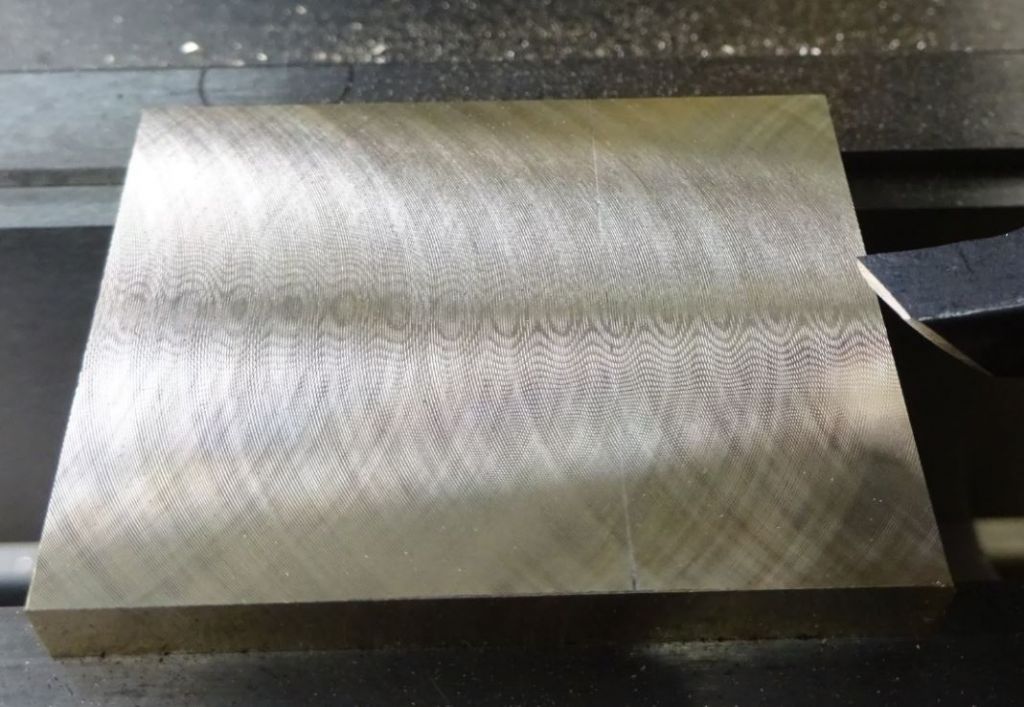
        Were you getting any back cutting from your cutter? have you trie dit left to right, right to left, front to back and back to front if it is truely in tram you should get the holographic cutting pattern snot a series of CCCC shapes

        flycut.jpg

        #662706
        Max Tolerance
        Participant
          @maxtolerance69251

          For many years I have used a similar method for tramming my mill head, except that instead of turning a piece of steel I use a large bearing inner ring. The one I have is around 220mm diameter and came from a scrap taper roller bearing at work. Needless to say these rings are ground to a very close tolerance and they are also hardened which is a bonus. The inner rings usually don't have any numbers engraved in them so there are no indentations to throw the readings out. Also of course you avoid the T slots in the table.

          #662710
          JasonB
          Moderator
            @jasonb

            Max, you should get a good reading as it sounds like you ar eusing the edge of the bearing but Chris's method uses the side of his cone wich will make any error unreadable unles sit is massive, all he is doing is centering his spindle to the hole.

            #662759
            Chris Mate
            Participant
              @chrismate31303

              Max, I was thinking about a taper roller bearing, but it would cost a lot for a large one, I will see if I can get an old unsold for years/discontinued one from local farm shop.

              Jason, here is added photo, I cut 3 rows right to left(X-Axis) and back over same cut, similar for other two.
              -The cutter have 6 inserts and the cut was .65mm. See if you can make something from it.
              -I can remove 5 inserts and cut again and see how that looks.
              -I can recut same depth from the Y-Acces the same way.
              -I cannot feel the rifs one see in photo, neither measure it with an .01 indicator.

              call5085_indicatortiptaper.jpg

              call5081cutx axisrightleftback 3 rows.jpg


              Edited By Chris Mate on 03/10/2023 22:45:52

              #662771
              Chris Mate
              Participant
                @chrismate31303

                Just to desribe my own understanding right or wrong as I see the Vertical(s) squared to the bed.

                -The bed=X & Y axis.
                -The rear fixed vertical with slide column=Lets say this is Z1 Axis.
                -Lets say the Quil slide movement is called Z2 axis.
                -Lest say the spindle movent with the quil is called Z2_1 axis, the spindle has no choice it can move with the quil or with the head crank up or down.
                -Lets say the spindle turning arc is called Z3.

                -The head and all in it can be cranked up or down in a fixed(Shimmed) vertical plane-Z1
                -The quil can be cranked in or out at whatever angle the head is -Z2
                -The spindle can go in or out of the head via quil- Z2
                -The spindle can turn the arc is -Z3.

                However the head Z1 is cranked up or down does nor represent the tramming to 90 degrees to bed of the spindle arc=Z3. If the head is at 45 derees, and the head is cranked up or down it will still move according to (shimmed) Z1 axis, however the spindle if quill is not moved will cut a round grove as the head is cranked up or down as a result in the work.
                Only when the quil is cranked the spindle will cut at 45 degrees into the work wherever it is positioned(Z1) to the work.
                If everything is square  to the bed the spindle arc wil run a horizontal circle on the bed or on top of the work, and then its called trammed in square to the bed, it will then run a perfect horizontal circle in a perfect barrel inside.

                Is this explained understanding basic of me correct-?


                Edited By Chris Mate on 04/10/2023 06:24:42

                #662774
                Michael Gilligan
                Participant
                  @michaelgilligan61133

                  That’s a bit heavy-going for my caffeine-depleted head, at 06:30 Chris

                  But I think I have two relevant comments:

                  1. You wrote ‘The head and all in it can be cranked up or down in a fixed(Shimmed) vertical plane-Z1’ … but Z1 is an axis, not a plane, and it’s generally better to keep your terminology consistent.
                  2. It appears that you are presuming that Z1 and Z2 are perfectly aligned in manufacture … but although ‘very desirable’ this [in the real world] is not inevitable.

                  Please excuse me if I have missed some subtlety in your phrasing.

                  MichaelG.

                  #662775
                  JasonB
                  Moderator
                    @jasonb

                    Chris just try what I said either putting a 0.1mm feeler gauge under one edge of your come or now using the traditional way of swinging a DTI.

                    The first I don't expect you to notice a difference in the amount of movement of the co-ax indicator needle yet the cone will be at an angle.

                    The second will confirm if your cone is giving you the results you think.

                    Yes I have said it several times you can only average things out tram is usually spindle axis in relation to the table but head/knee axis and quill axis are unlikely to be the same, quill is hardest to check as there is movement in it and a very lightweight hobby machine may even flex a sthe quill handle is pulled down.

                    Video I did a few years ago spindle to table is good, head not bad and quill showing more deviation.


                    Edited By JasonB on 04/10/2023 07:45:05

                    #662815
                    Graham Meek
                    Participant
                      @grahammeek88282

                      Hi Jason,

                      I can re-iterate the flexibility of the Hobby machine. My Emco FB2 would always read out in the Y-Axis direction across the table. This is something other users have noticed. We are only talking a total 0.03 mm over 150 mm which meant the Column was leaning to the rear of the machine.

                      However when extending the head to the top of the Z-Axis travel the reading then became zero-zero in the same direction. My reasoning behind this was that as the Head moved up the Column. The overhanging weight of the Head was inducing a bending moment in the Column.

                      As an exercise in futility I shimmed the Head to to get it correct, down close to the table. Putting the Head at its extreme Z position. This showed the same 0.03 mm error but in the opposite direction, (Column leaning towards the front). Which was what I would expect.

                      Clearly Emco had worked this out in the design stage and compensated for it in manufacture. The bottom line is that for the money we are not going to get Jig-borer precision and a compromise needs to be made. Given the work I had completed on this machine both privately and commercially this inaccuracy never once let me down. It is after all only 0.01 mm over the width of a 50 mm shell mill, which is probably being deflected by this amount due to the cutting forces.

                      Regards

                      Gray,

                      #662848
                      Chris Mate
                      Participant
                        @chrismate31303

                        OK, I had determined that as everything is connected(Not to same point) I get 1 mark on screen movement for coaxial indicator(as in photos) and .03mm movement for a dial indicator pointed at the MT4 collet chuck position clamped to the vice rear. …..This was manupulating the Z2-Axis, by changing it from the Z1 axiss it rides on.

                        I accomplish the movement by adjusting the head bolts added to this mill for minimally aljusting the head, forcing the head down, as the head "lean back" slightly as was said. With this mill you can do this, I have however seen that newer models from same supplier this function was abcent, so your head stay as its bolted(3x bolts) to slide on column. I used this in the beginning after getting the mill and trammed it the usual ways.

                        There is no way I can manupilate the X-axis controllably(Hap hazard by tapping it) by bolt adjustment, unless I make up a sturdy 2x bolt contraption to accomplish this to my liking of doing it

                        Yes, I accept this mill is probably worse than a 1960 farm tractor in build, but having low standards help along, and assisting me in making things for myself its more valuable than I though after buying it, its just interesting getting deeper insight into things as I go along..

                        The fact that surface grinding technologie/machines exist, make me feel better.


                        Edited By Chris Mate on 04/10/2023 15:50:21

                        #681565
                        Chris Mate
                        Participant
                          @chrismate31303

                          Ok, one thing led to another(S):
                          1-I made a double indicator tram setup, using 1-2-3 blocks and/or just to bed/table. I found the Y1-axis side a slight problem as decribed by others, where as I undestand the geometry of the Y1-axis around the centre of the spindle is not similar to the X1/X2 axis(Y2=OK), due to head/Slide adjustments. Interesting changes happens to the Y1 & Y2 points if I adjust those two nuts extra on head which other similar mills probably dont have. I will have to chew deep on this one.

                          2-Using it I dicovered the spindle moved up & down and sideways too much for any liking. I could have a good tram say 2 out of 10 times turning the spindle, its not reliable.

                          3-I made a tool/setup to replace the bearings, the inner sides as well as outer sides in quil, minor mods same tool for both. I did this after local Case TRactor shop broke race of the larger Timken bearing, bought another one.

                          4-Removed Quil/spindle. Removed chinese bearings and replaced today with Timken made in Poland roller tapered bearings. I noticed to preload the bearings is not that difficult in this case…You press last small bearing in with spindle in quil till it feels like tentioned..If its too much, you just tap the end back with an aliminium hammer(Or other safe hammer)…You then righten the in this case one locknut & washer locked. The locknut can be used to apply load after the bearing initial seating by pressing it in..I played around between the locknut/washer & tapping to get the preload I am happy with.

                          5-The relief of this was a pleasure, zero play up/down or sideways, I was happy with preload and no play. I expect to see a different cut pattern now.

                          6-This brings me to the looseness of original chinese bearings.. Could it be due to tapping out the MT4 tools.. In beginning it was hard tapping, but after a tip from this forum I made a handwheel, similar size to an old Singer knitting machine with socket to tighten drawbar with hand, since the the knock loose was not an issue as to feel…….Now that I assebled the spindle/quil myself, it would be easy to detect if knocking out the MT4 tools is a problem.

                          I took photos and will post it later. I am busy reassembling everything again, and will tram it again to see the difference in feel of doing it.

                          #681642
                          JasonB
                          Moderator
                            @jasonb

                            I adjusted my loose Chinese bearings the day I got the machine and have been knocking the drawbar for 15 years and not had to touch the bearings again. Tightened with a standard length combination spanner, hit with Thor copper hammer so probably more weight behind it unles syou have a big aluminium one.

                            Had you adjusted the old ones before and not managed to get rid of the play you say you had?

                            #681757
                            Neil Lickfold
                            Participant
                              @neillickfold44316

                              After talking to a person who used to build spindles, he was telling me about the flexibility of the spindle shaft when the bearing is placed on the shaft, and how the way the lock nut is torqued up against the bearings inner race. When done correctly the spindle will run true on it’s bearings and the inner of the spindle will also be true. Occasionally when the inner race is tightened by the lock nut, the spindle does not spin true, making the inner run out from the shaft and bearing set. The fix was as simple as un loading the underside of the nut facing the bearing race. So it was usually sanded or stoned slightly so that when it was correctly torqued down, the area that need less load was in the correct radial place. When the spindle was tested on the bench to be running all true, then you could assemble it into the housing and redo all the testing again with the correct bearing preload applied on the outer to inner race and the top bearings put into place, and retested again. The reason that this came up is because when this assembly is not correct, you can have a spindle that when the tram or run of the spindle does not follow the run of the spindle body. A light turned on, and is one of the small issues I have with the spindle assembly on my HM50.  In an extreme case, this spindle run out can be as much as 0.06 or 0.07mm difference on the tram on the table, not matching the bottle square test. So the head can be shimmed etc to cut a nice double cut even pattern, while at the same time, when the quill is moved around 40mm to 50mm of movement, the centre of the drill or cutter could be out by 0.07mm or more. This is what I will be looking at when I get the rest of the other projects sorted, and I have  the weekend to take it all apart and recheck and see what I overlooked when I had it all apart the other year.

                              I have brought this up as it was new to me, to find out, how much the nut had on the influence of tightening the inner bearing race as to effectively be the cause of a bent spindle assembly. So we al learn something new every day or every week. Hoping that this may help out others who have replaced bearings, only to find that things are not the same as it used to be.

                              Neil

                              #681768
                              Neil Lickfold
                              Participant
                                @neillickfold44316

                                https://youtu.be/grUdsTTRGl4?feature=shared&t=4176    At 1hr 9 mins is a good explanation .

                                #681794
                                Zan
                                Participant
                                  @zan

                                  I cannot see how this will work.   Let’s say the outside of the device is machined concentric with the cone ( at the same time)

                                  So the cone is set exactly in line with the spindle axis using the outer face

                                  the indicator in the taper shows the head is out of tram and needs to be knocked say clockwise

                                  so you thump it clockwise and get zero on the indicator  head square  (?)

                                  BUT the bottom of the indicator has now moved to the left and is no longer on the axis of the spindle  and clocking again on the outside will show an error.

                                  so move table to left  to centralise on the axis

                                  oh dear. Not true again when testing the taper………. Thinks…..the head must be out


                                  i tram mine by using a new brake disc and a dti on an arm. The disc is perfectly [ for me] flat and eliminates any error when the dti drops and lifts when crossing the t slots


                                  JASON , a theoretical point. your explanation of back cutting and flexing.   On a long workpiece [ greater than the swept dia. Of the cutter), a single point cutter the cutter will flex up  then do a scrape cut on the back cut.. however if there are two cutters mounted at 180 to each other when the front one flexes up the back one will be forced down.  So the result is a flat   But as soon as the initial cut passes over the end of the work, the back cutter is no longer being forced down so wil in effect lift clear of the work. Result, not flat. So the pattern on the work different….

                                  im ready to be shot down in flames over this!

                                  #681881
                                  Chris Mate
                                  Participant
                                    @chrismate31303

                                    The reason I replaced the bearings was that to do anything I had to take the quil and spindle out, the bearings was not expensive enough not to do it while I am at it. 2ndly it is an experience I wanted to do, and am glad I did.

                                    -This quil was machined to have either smaller bearings, other type of bearings as well. This mill has tapered roller bearings fitted, even if the manual says ball bearings.

                                    I assembled everything today, start it, measured the amps in each gear and at least that seemed normal, so will see tomorrow if I guessed the preload ok enough, and how it clocks(Up/down, play, runout) and tram(Looking for stable reading right or wrong.. If I have to redo everyhting, that also ok at least I have the tools to do it now myself.

                                    #682615
                                    Chris Mate
                                    Participant
                                      @chrismate31303

                                      Ok, today was a Kwil day.

                                      After running the mill, I decided I don’t like the temp buildup, the amperage looked ok. I removed the quil again, loosen the locknut, and give the spline side of spindle with quil bottom supported two taps, tighten the nut to that space. I observe more free movement with still no play up/down, or horizonal(Very pleasing). Measuring the runout between quil and spindle, it was virtually zero with dial test indicator, very pleased with this outcome as is now, never seen this on this mill when brand new.
                                      I also removed a bit of extra grease. This is not the same as a car bearing enclosure between seals, the grease can move away(Observe capscrew space below lower bearing). Its also not like a car free movement determind by locknut, you have to tap the top bearing and lock the nut to that position. You can force it more stiff with the locknut, but to loosen you must tap(This tapping does not concern me), top bearing not as tight fit as bottom one.

                                      Bearings used:Made in Poland
                                      Bottom=Timken X30208M M24
                                      Top=Similar 30206.

                                      Grease used:
                                      Marine bearing grease
                                      Lithium/Calcium base/NLGI 2

                                      I will try to “break it in” somewhat and see how it ends up, the current in higher gears are now somewhat less than before with very slight heat….Will see how this works out.


                                      #682833
                                      Chris Mate
                                      Participant
                                        @chrismate31303

                                        For what its worth:Current draw differences between after fitting the bearings and preload guessed and after preload reset. 220V 2KW motor+gearbox

                                        1+L    =2.6A…………………2.48A

                                        1+H    =2.75A……………….2.5A

                                        1+M    =2.66A……………….2.49A


                                        2+L     =2.92A……………….2.63A

                                        2+H     =5.09A………………3.74A

                                        2+M     =3.46A………………2.75A

                                        Still no play& heat build up all seem ok

                                        #683375
                                        Chris Mate
                                        Participant
                                          @chrismate31303

                                          Photos  in order……See difference in finish before and after bearing replacement with no play……With the play up/down and sideways it delivered a sorts of an arty polished finish which felt smooth. After it delivered a different finish also smooth to the touch. Showed bearing fitment tool(Scrap metal used, I dont have a press yet) which actually gave me a nice control screwing the bearing in. It works on spindle and minor additions in quil as well. I used a split washer which provides nice control making sure bearing parts are  lined up well before screwed in place.

                                          Unfortunately site does not allow me to show images here with post, look at galary.
                                          https://www.model-engineer.co.uk/members/chrismate31303/mediapress/tramming-mill/


                                        Viewing 19 posts - 26 through 44 (of 44 total)
                                        • Please log in to reply to this topic. Registering is free and easy using the links on the menu at the top of this page.

                                        Advert

                                        Latest Replies

                                        Home Forums Beginners questions Topics

                                        Viewing 25 topics - 1 through 25 (of 25 total)
                                        Viewing 25 topics - 1 through 25 (of 25 total)

                                        View full reply list.

                                        Advert

                                        Newsletter Sign-up