Hi Ian Hi All
As shown in the following link: **LINK**
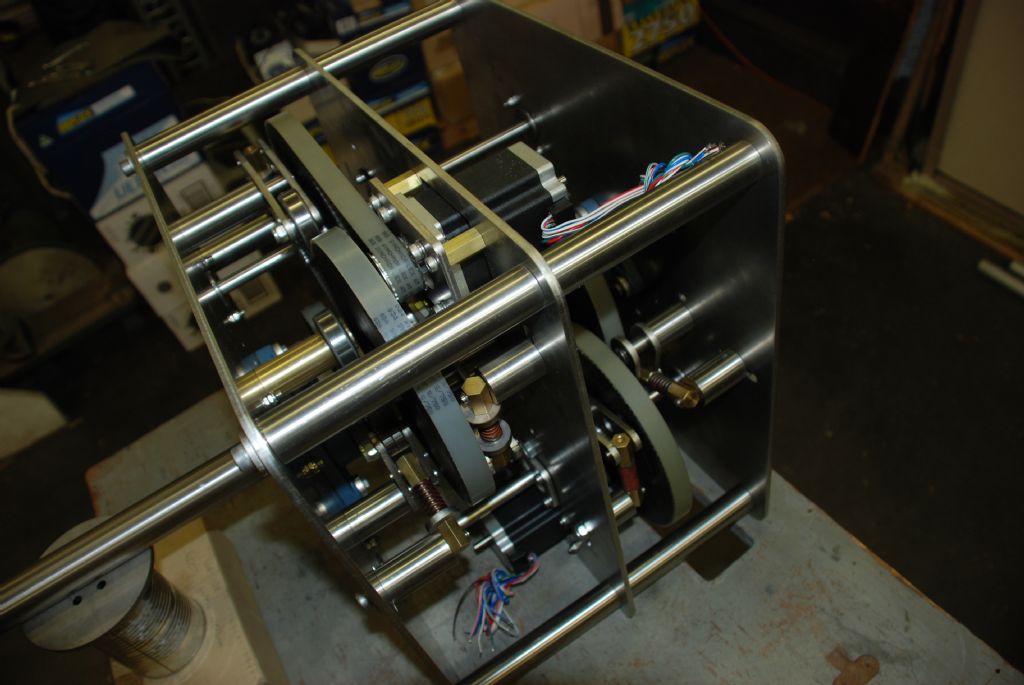
Snap ring groove bearings have a stout snap ring, or circlip, fitted in an off center groove machined into the outer ring of the bearing, the ring projects about 2.5mm. When working with laser cutting easy to clamp in position by using the circlip as a mounting face. in the clock design more than adequate holding considering the forces involved, in fact a very strong mount the snap rings are quite heavy gauge.
To mount them I simply place a hole at the bearing diameter surrounded by four bolt holes in the plate design then draw a small matching clamp plate again at bearing diameter surrounded by four matching holes and the job is done. When assembling they are just slipped in and once clamped are quite firm.
OK this is not the ideal setup for a super precision machine, however in this application .01mm location accuracy for hole placement was more then adequate to locat the shaft. What I was looking for was low friction, long lasting lubrication and radial stiffness with limited axial stifness, they are simple deep groove ball bearings that always have a small amount of axial play.
When working with laser cutting you have to free your mind of the normal "Too much time and too hard to make make" constraints you place on a part design. You also have to rethink the design to use flat plates as much as possible, even if you have to stack them up it does not matter, the laser is so fast travelling at many metres per minute, it will do the entire job in a few minutes anyway. If possible it is less expensive to not use many thicknesses of material, thus minimising the number of setup charges from the laser cutter.
Most small jobs like this clock simply attract the minimum charge anyway so dont worry about adding lots of complexity and many parts.
Nearly all free 2D cad packages can output a DXF text file, and just about all can can draw polylines for the cut line. The laser cutter will convert the file to match their machine. Alternatively just give them an accurate drawing and they will draw it in cad for an extra charge. Most will be happy to check a file for you and advise you of any changes needed to work with their system. Some will email you a help sheet.
The pillars in this clock are 25mm diameter drilled and tapped M8 at the ends, the pillars were turned down to 15mm diameter over 2mm creating a step at each end. The pillars are located in 15mm holes in the side plates on that step. they were screwed on a stud on the centre plate then the outer plates were fitted with M8 cap screws on laser cut 5mm washers. I did not want to rely on the M8 bolts for location this method is more accurate.
The 45mm (Finished size) hour shaft is indeed tube about 1200 long. One of the more difficult parts to make, thick walled SS tube turned out to be hard to get and when I did get it it was a rough forged finish. And it was not very straight! Several frustrating hours were spent machining it. Ther are several steps and it had inserted bushings requiring press fit boring in both ends.
The spring loaded ball race is used as a belt tensioner. once installed the clock will be left for long periods without maintenance, Hopefully the tensioners will take up any wear and keep the belts tight. it was also thought that it would reduce the any backlash that might show up in buffeting wind. The parts were in the main just added the the laser list. although the brass clevis / spring assembly did take a bit of time to make. The spring is a Die spring a lot stiffer than it looks.
Cheers
John
Edited By John McNamara on 09/05/2013 02:16:52
John McNamara.


