tool-to-parts contact detection using an old multi-meter

Advert

tool-to-parts contact detection using an old multi-meter

Home Forums Electronics in the Workshop tool-to-parts contact detection using an old multi-meter

Viewing 13 posts - 1 through 13 (of 13 total)
  • Author
    Posts
  • #601657
    Y C Lui
    Participant
      @yclui16187

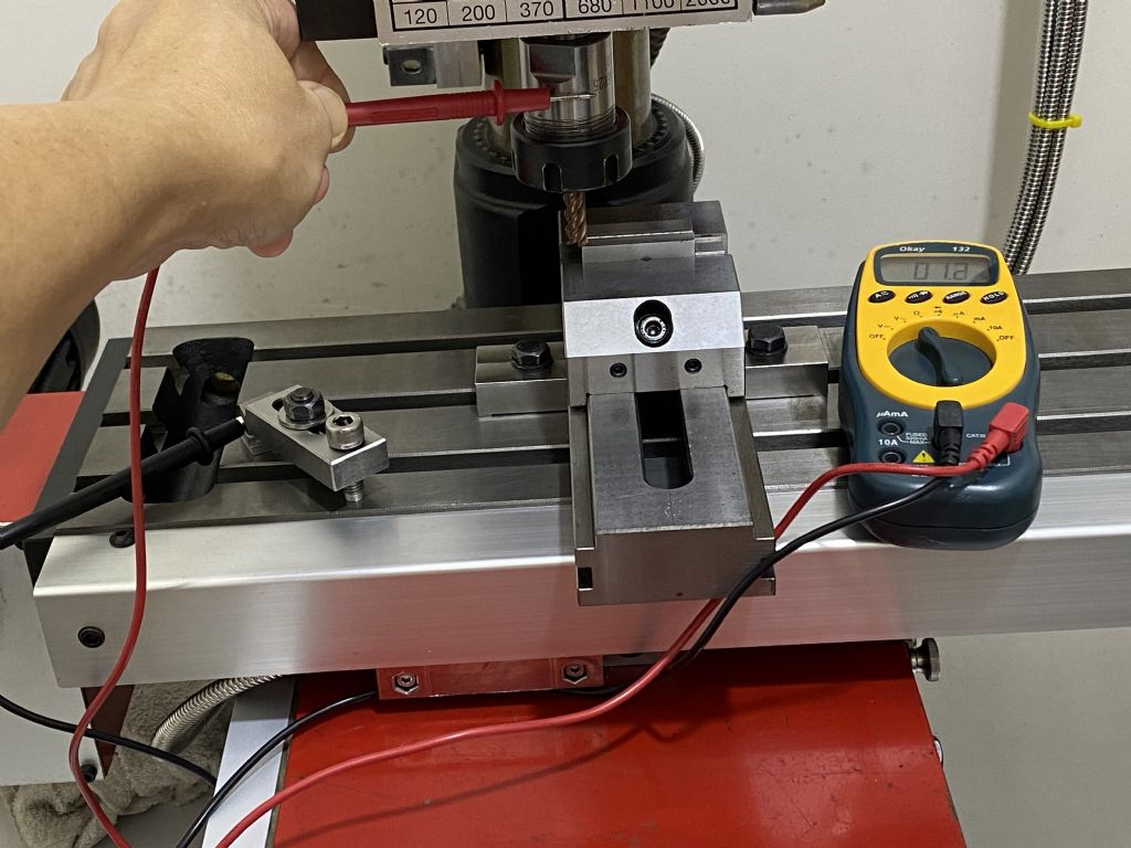
      I tried today using my 30+ year old and cheap multimeter as a touch sensor for my Emco FB2 bench mill and much to my surprise, the precision is VERY good !

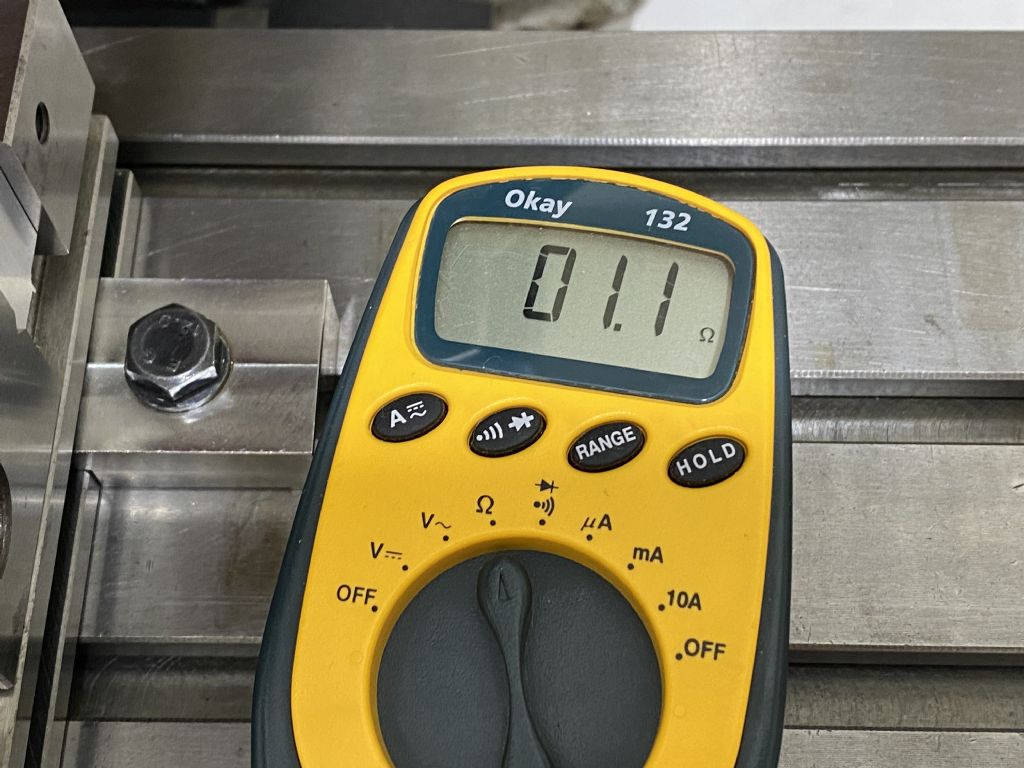
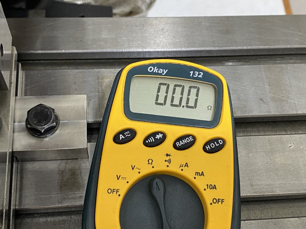
      With one probe touching the table and the other touching the arbor, the resistance measured is 1.1 ohm when the tool is not in contact with the workpiece. This value varies a lot depending on the angular position of the spindle. It can go up to something close to 10 ohms but it never went below 1 ohm. As soon as the tool comes into contact with the workpiece, the reading would drop sharply to zero.

      To test the precision, I made a shallow cut on the top of an aluminium block with the end of the mill ( 8 mm carbide ) to get a clean datum surface. Then I raised the head, connected the multimeter and very slowly lower the mill head until a sharp drop in reading occurred. Then I locked the head, painted the workpiece surface with a marker pen and did another pass. The paint was not scratched a bit. After that I lowered the head by just 0.005 mm ( or 2 tenths of a thou ) and cut again, the paint was completely removed. This proves that cutter was brought back to the original Z position with practically zero error.

      I will definitely use this method a lot more in the future.

      multimeter set up.jpg

      not in contact.jpg

      after contact.jpg

      Advert
      #32263
      Y C Lui
      Participant
        @yclui16187
        #601663
        Gary Wooding
        Participant
          @garywooding25363

          That's very interesting. Because the the machine itself is conductive, I just assumed there was no point in electrically detecting contact between workpiece and tool, but your successful experiment shows how wrong I was. Thank you for a very interesting result.

          #601665
          Y C Lui
          Participant
            @yclui16187
            Posted by Gary Wooding on 14/06/2022 10:04:21:

            That's very interesting. Because the the machine itself is conductive, I just assumed there was no point in electrically detecting contact between workpiece and tool, but your successful experiment shows how wrong I was. Thank you for a very interesting result.

            This is actually not my idea. I learned about using changes in resistance to detect contact from this article . The arthur has also got a Youtube video . I am in the process of building the detector which is very simple and should work very well.

            #601668
            SillyOldDuffer
            Moderator
              @sillyoldduffer

              An analogue meter should perform even better. A problem with digital meters is they're relatively slow because the analogue voltage has to be digitised, processed, and displayed. Each stage adds a delay, which is often noticeable, plus the operator has to react to it. So the operator is likely to still be moving the head well after first contact.

              Analogue meters respond much faster, the delay being mainly the time taken to accelerate the needle and the operator noticing it's moving. Faster still is a lamp or LED, both being practically instantaneous. That leaves the operator's visual system, which is also surprisingly slow, taking about 0.2 second to respond. Ears are quicker, about 0.16s, so in theory a circuit that beeps on contact should be the most accurate. Best way of detecting actual first contact is to eliminate the human!

              I doubt the digital meter's result is really good to within 0.005mm, but don't let that put anyone off – the method is useful and potentially improves on the alternatives. I usually whisk off a bit of cigarette paper stuck to the job with a drop of oil, a method which also has accuracy reducing shortcomings! However, I think cigarette paper partly compensates for the operator's slow reactions, and might be best for some people, we're all a bit different. First contact is with the paper about 0.02mm away from the metal, so by the time the operator stops advancing the tool, the cutter is significantly closer to it. Not spot on, but good enough for most purposes.

              Dave

              #601674
              John Haine
              Participant
                @johnhaine32865

                Yes, this method can work well. My interest is in using it for CNC tool setting, where really it needs to be completely automatic and not require any calibration. I looked into using a resistance measurement but the resistance change is small and inconsistent. A better approach is to sense the magnetic field round the tool/probe generated when a current is fed into the spindle, which normally runs through the machine but some gets diverted on contact. My own implementation uses AC and a toroidal current transformer, but a student of mine built a version using DC and hall effect sensing using an HED in an air gap in a toroidal core, which worked equally well. The current in the tool varies from zero before contact to potentially an amp or so on contact so sensing is much easier. More details in the thread below – Joe Noci's thread on a CNC lathe but he asked me for more details. I can confirm that one can get micron level repeatability.

                **LINK**

                #601703
                Nigel Graham 2
                Participant
                  @nigelgraham2

                  I've often thought about that, though in practice I use either the oiled-paper or wiggler. If the distance from the cut feature to the edge is not ever so fussy (e.g if what matters is the pitch of a set of holes along a piece of hot-rolled steel), sometimes I simply eye the alignment of a centre-drill point with the edge.

                  To answer Gary Wooding's question further; yes the path between work-surface and tool is all metal-to-metal but via lots of joints, each adding a tiny resistance, and each of most of those joints holds a film of oil that increases its the resistance further. So although the cumulative series of resistances is very low, it is enough for a reasonably sensitive meter to detect.

                  '

                  I had thought a lamp, either filament or l.e.d, might be an even sharper detector because it is either on or off, though a filament one at least is likely to glow more dimly than it otherwise would for the same battery voltage.

                  Then having posted that, realised my mistake there and came back to edit it!

                  I had half-remembered my old idea of using as the machine contact, a metal ring pressed or glued onto a rigid plastic mandrel and finish turned to a set radius; this assembly to be held in the chuck or collet. Therefore the circuit does not go through the machine itself, and presents a switch rather than change of resistance to detect.

                  Edited By Nigel Graham 2 on 14/06/2022 14:44:33

                  #601707
                  old mart
                  Participant
                    @oldmart

                    I can see the principal and it should work every time, but you must be sure that one of the flutes is exactly in line with the spindle to work axis when you make the measurement. For example, if the work is only 1mm thick, it would be possible to position a four flute cutter exactly between two flutes which would not be on the outside diameter.

                    #601712
                    SillyOldDuffer
                    Moderator
                      @sillyoldduffer

                      One of my books gives figures for some locating methods, unfortunately not all of them.

                      From worst to best:

                      Cone into hole (how I do my rotary table) – ±0.005"
                      Wiggler needle – ±0.003"
                      Laser pointer – ±0.002"
                      Electronic Edge Finder – ±0.0005"
                      Mechanical Edge Finder – ±0.0002"

                      Interesting how good a mechanical edge finder is, ten times more accurate than a laser pointer! But laser pointers are designed to find cross-hair markings or centre-punch holes, which an edge finder can't do, and a laser pointer is quicker and more accurate than a wiggler needle, which I also depend on.

                      Note how difficult location inaccuracies make it to work accurately in tenths!

                      Dave

                      #601786
                      Y C Lui
                      Participant
                        @yclui16187
                        Posted by SillyOldDuffer on 14/06/2022 15:10:15:

                        Interesting how good a mechanical edge finder is, ten times more accurate than a laser pointer!


                        Mechanical edge finder is my prime tool for edge detection and I have no intention to replace it with anything other means. The only limitation is that the tool is good for X Y only. For the Z axis, I need something else. I have got a Z axis tool setter but the set up is kind of slow and you need to know the height of the reference surface of the workpiece above the table. This means additional measurement and calculation hence time.

                        img_6213.jpg

                        I haven't tried the cigarette paper + oil method but I have tried tapes. The method works but if the tool is not an end mill or the part of the workpiece being touched is not a flat surface, it is not usable. Just some examples that I have come across : 

                        – The pointed tip of a chamfering tool touching the workpiece surface

                        – The end of an end mill touching the corner of a workpiece clamped at an angle

                        – The tip of a boring tool touching the inner surface of a hole


                        Edited By Y C Lui on 15/06/2022 08:27:56

                        #601797
                        SillyOldDuffer
                        Moderator
                          @sillyoldduffer
                          Posted by Y C Lui on 15/06/2022 08:15:09:

                          Posted by SillyOldDuffer on 14/06/2022 15:10:15:

                          Interesting how good a mechanical edge finder is, ten times more accurate than a laser pointer!

                          I haven't tried the cigarette paper + oil method but I have tried tapes. The method works but if the tool is not an end mill or the part of the workpiece being touched is not a flat surface, it is not usable. Just some examples that I have come across :

                          – The pointed tip of a chamfering tool touching the workpiece surface

                          – The end of an end mill touching the corner of a workpiece clamped at an angle

                          – The tip of a boring tool touching the inner surface of a hole

                          I recommend cigarette paper, but you're right – it's not always suitable. I don't know of a single way of locating edges, marked out lines, and holes etc, even without having to account for odd tool or workpiece geometries.

                          I've been investigating a point made by Ramon Wilson in another thread were he claims centre-finding with a DTI is more accurate than doing so with an edge-finder. He could well be right and I'm nowhere near proving otherwise. However, one source, without explaining why not, simply says 'you can't accurately centre find a hole with a DTI mounted in the spindle'. Then goes on to describe:

                          • a flexible arm arrangement that clamps above the spindle, allowing a DTI to be used with the cutter inserted and ready to go
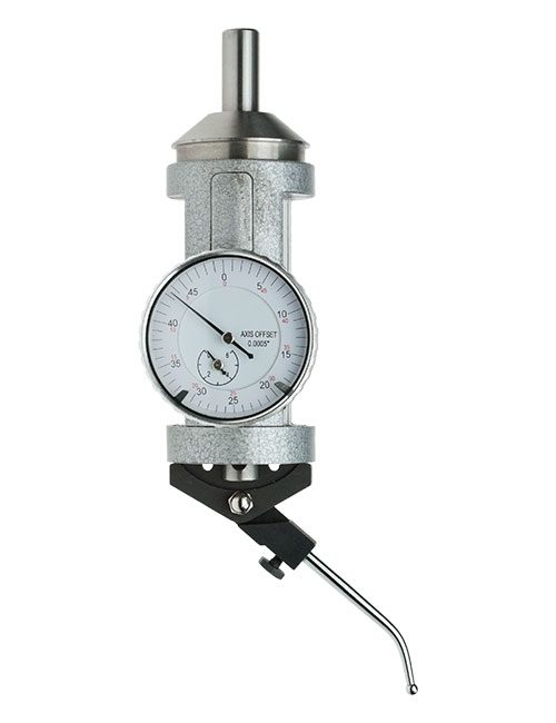
                          • a 'coaxial centre indicator', alias 'Dial coaxial centering Indicator' like this example from ArcEuro. These look much easier and faster to use than the DTI on an arm arrangement. (Anyone able to confirm this, I've not used either system.)

                          Both methods are comparative, that is no actual measurements are taken. The instrument is considered centred when the dial registers no movement as the spindle rotates. Accuracy is limited by the mechanisms ability to amplify tiny movements up through a sticky gear train and then shift the dial needle far enough for the operator to see it. A well-made instrument would outperform a cheap one, but neither would impress a metrologist! Fortunately, none of the machining I do has to be accurate within measured tolerances: my parts only have to fit together, and I don't provide interchangeable spares!

                          Dave

                          #601815
                          Kiwi Bloke
                          Participant
                            @kiwibloke62605

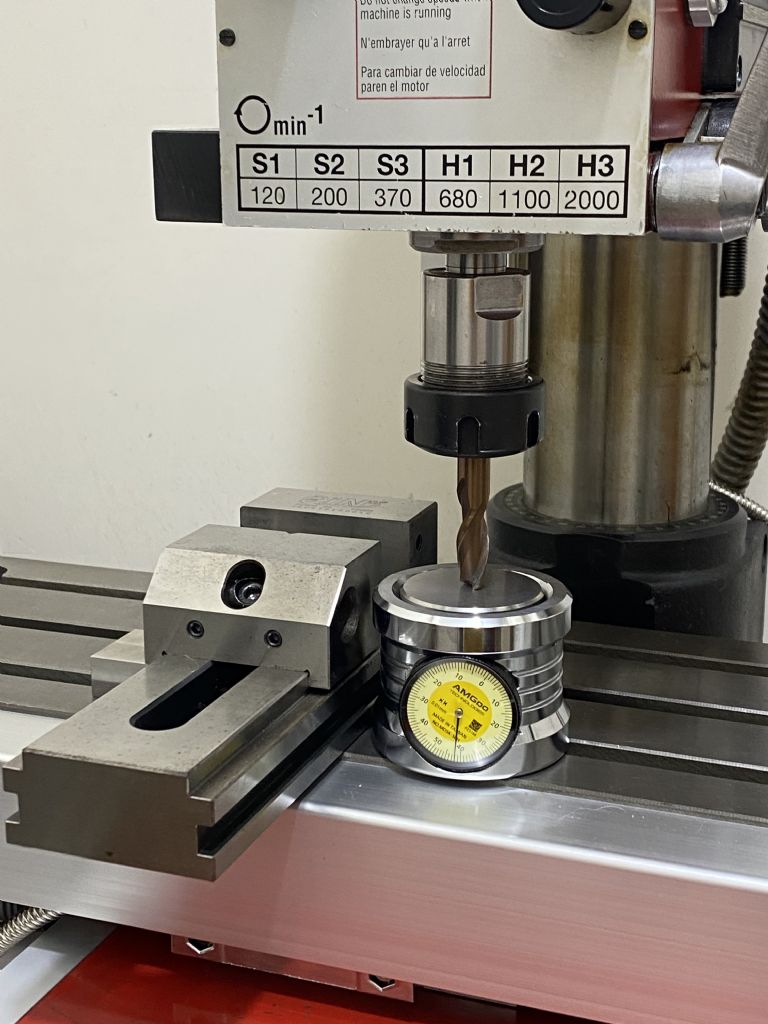
                            The device pictured above is an oriental knock-off of the American Blake Co-ax indicator, which was priced at $267 in 2006. I daren't look up its current price! Blake claim centring to within two 'tenths' (imperial), but I don't trust mine to better than just under a thou. Compared to a lever-type indicator on a fixture in the spindle, it's a rather more complex mechanism, necessitated by the nice feature of having the dial assembly not rotating with the spindle. The complexity must be paid for in accuracy and repeatability, and wear. A simple 'indicator on a stick' can be as sensitive as the indicator (one tenth indicators are common enough, if expensive), and there's nothing twixt workpiece and indicator to add error. However, the Blake is often quicker and more convenient to use – provided there's enough headroom. An indicator on a stick is more versatile. Of course, this assumes the 'stick' is satisfactory. Look through Stefan Gotteswinter's videos to see his in action in many and varied applications.

                            Edited By Kiwi Bloke on 15/06/2022 11:45:44

                            #601819
                            Y C Lui
                            Participant
                              @yclui16187
                              Posted by Kiwi Bloke on 15/06/2022 11:40:18:

                              The device pictured above is an oriental knock-off of the American Blake Co-ax indicator, which was priced at $267 in 2006. I daren't look up its current price!

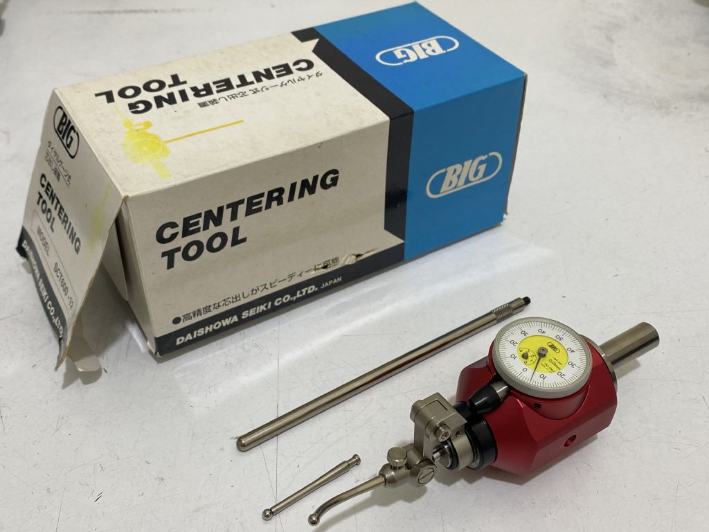
                              I bought this Japanese version some 20 years ago. Very well made but I never used it because I found it to be inaccurate when I first tried it out on my Emco FB2 bench mill. Then as I learned more about my machine, I found that the error was solely due to the misalignment of the mill. Neither the column nor the spindle was perpendicular to the table so the X Y shifted when the head is moved up or down. Now the aligment issue is sorted out but I still do not use the tool because I had to move the head up by quite a lot before there is sufficient vertical space to accomodate the tool. Kind of tiring. Will let it go if anyone is interested. The condition is close to new.

                              img_7063.jpg

                            Viewing 13 posts - 1 through 13 (of 13 total)
                            • Please log in to reply to this topic. Registering is free and easy using the links on the menu at the top of this page.

                            Advert

                            Latest Replies

                            Viewing 25 topics - 1 through 25 (of 25 total)
                            Viewing 25 topics - 1 through 25 (of 25 total)

                            View full reply list.

                            Advert

                            Newsletter Sign-up