Good morning all, and Seasons Sunday Greetings.
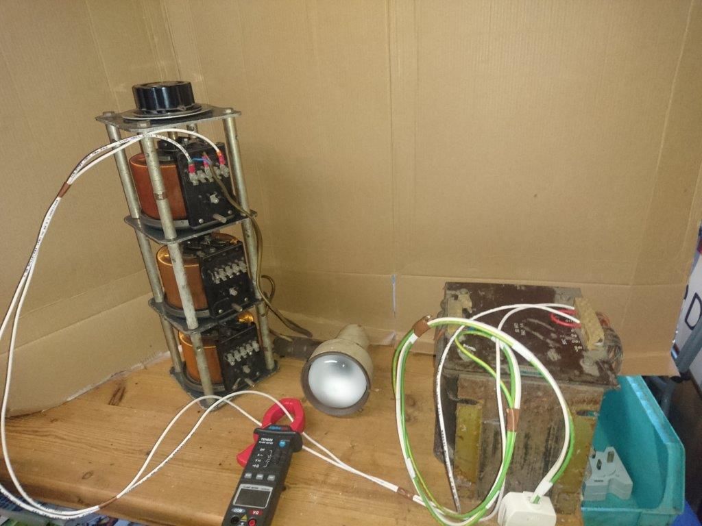
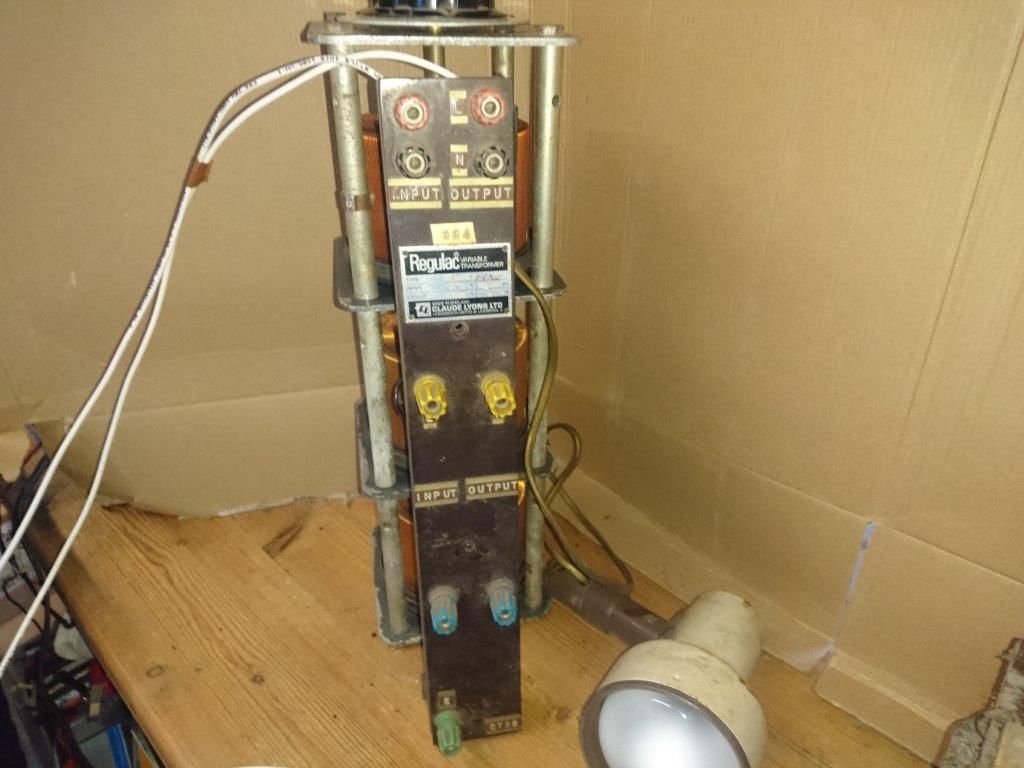
I have been given a three phase variac, but it's not all it seems.
Firstly the details:

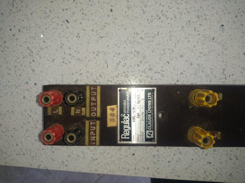
That little identity plate shows it as type no RB2L-G3M
Input 208 volts 50/60 Hz
Output 0 – 234 V 5A
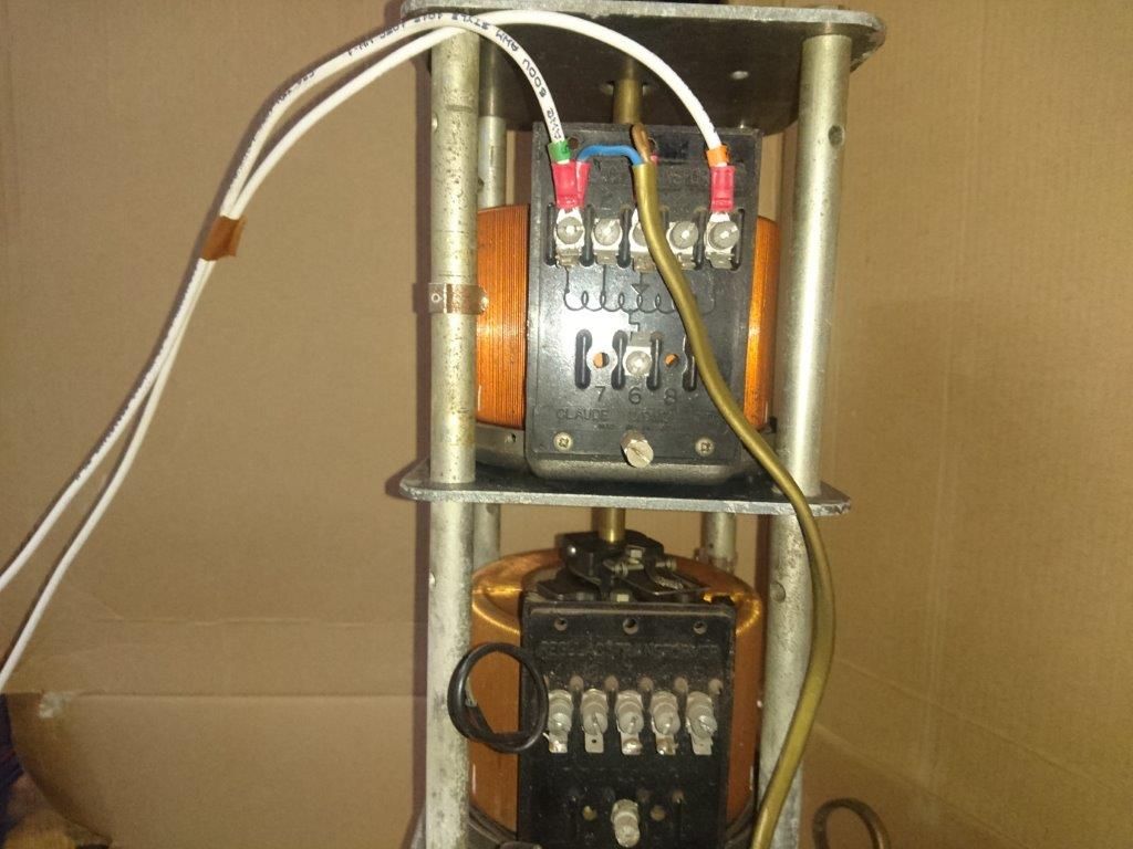
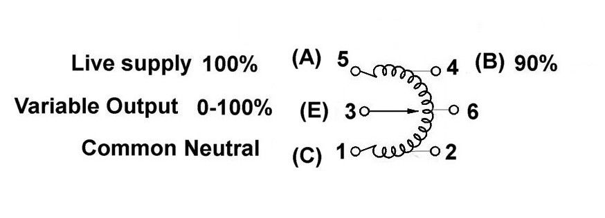
When I stripped the covers off to discover if it was safe to energise, I found the wiring to the input and output terminals had been cut. I've freed up the mechanism and cleaned it and now have energised it but have run into a problem with the applied voltage.
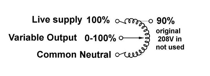
If I apply 50 Hz volts at 115 volts to one of the three sections of the transformer across the windings. the static no load current is about 130 mA. I can vary the output voltage with the position of the slider all exactly as I would expect a Variac to behave.
If I increase the input voltage to 210 volts the static no load current hikes up to over 6 amps, and the magic smoke appears as the windings overheat. Turn it off and have a rethink!
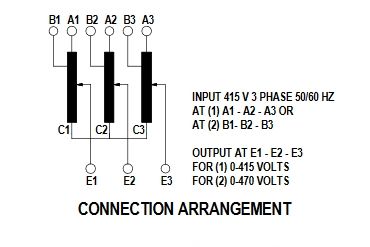
If that input voltage figure is to be interpreted as 208 volts line to line connected in delta that would correspond to 120 volts line to neutral in star., which gets me into the envelope where the thing seems to be happy. Is that what the nameplate means?
I assume what is happening with my 210 volts applied directly across one of the transformers (ie star connected) is that the core is going into saturation, and thus the inductance of the transformer plummets and the current isn't controlled by the self inductance of the winding. Anyone got any better ideas?
Thanks as always in anticipation
Best rgds Simon
x
 Robert Atkinson 2.

