Three Cylinder Steam Aero Engine

Advert

Three Cylinder Steam Aero Engine

Home Forums Stationary engines Three Cylinder Steam Aero Engine

Viewing 14 posts - 51 through 64 (of 64 total)
  • Author
    Posts
  • #535129
    JasonB
    Moderator
      @jasonb

      They look like small 1/8" BSP/NPT street elbows, This is the common way most American engines are plumbed both model and full size with what look like mallable iron fittings. The three nutted unions do look a bit on the large size and could be reduced down a bit. EKP sell them in BSP.

      If pipe sizes are smaller then the cast "trees" from P M Research will give the same look.


      Edited By JasonB on 21/03/2021 07:13:11

      Advert
      #535280
      John Purdy
      Participant
        @johnpurdy78347

        Jason

        When I said the plumbing looked like commercial tube fittings I should have said pipe fittings as you say. The plans call for the inlet on the valve body to be tapped 1/4 NTP, so I assume all the fittings in the picture are 1/4 NTP. I agree that the union look too big, so am trying to come up with something that looks a little better. PM Research do a 1/16 NTP union which might look better.

        #535303
        JasonB
        Moderator
          @jasonb

          1/4" BSP would be the nearest match to 1/4" NPT. As I said EKP do them but you could shop around and find them a bit cheaper, I used to get them from a supplier that did stuff for narrow boats but they seem to have disappeared.

          The 1/16" unions from PMR would be too small but they are easy enough to make from hex stock which is what I usually do for the American Hit & Miss Engines and if you use 40tpi ME threads for the internals they look OK. I've got some sizes that I used knocking about somewhere so will did them out.

          #535353
          John Purdy
          Participant
            @johnpurdy78347

            I just realized that for some reason I said the pipe fittings are 1/4 NTP and that the valve body was trapped 1/4 NTP when they are actually 1/8 NTP as Jason said. The valve bodies are currently tapped 3/8 – 32 but that can always be changed!  I have thought about making the couplings,  I don't have any large hex but have some round that I could make hex out of.  I seem to recall that there was article in ME about making couplings with dimensions for various sizes of tube, have to see if I can find it.

            Edited By John Purdy on 21/03/2021 22:52:19

            #537359
            John Purdy
            Participant
              @johnpurdy78347

              img_61055.jpg

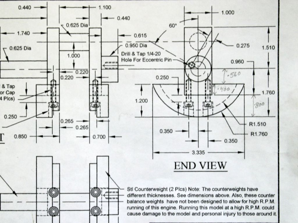
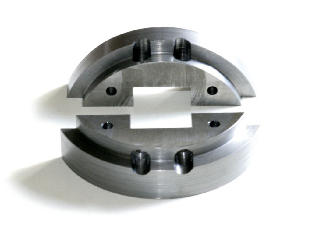
              For the crankshaft counter weights, two slices of steel were sawn off some black plate and machined to be slightly oversize, finishing at 3.375 ( 3.378 ), 1.240 ( 1.260 ), and .851 ( .701 ). The holes for the 10-32 hex socket head cap screws for fixing them to the crank web were then drilled #21 tapping size and counterbored 5/16" diameter. Also two #21 holes were drilled in each for some 10-32 bolts to fix them to a jig plate to be bolted to the faceplate for turning the weights to the semi circular shape. These holes were positioned so that the heads wouldn't be in the way of any of the turning operations. When completed these holes will be plugged with some short lengths of 3/16" dia. rod. I had first considered putting the hold down bolts in the centre section that would be cut out for the socket that goes around the crank web but felt that this wouldn't provide a secure enough hold for the intermittent turning operations.
              Before mounting on the faceplate for turning, the corners were sawn off and they were milled to remove the remaining corners and bring them to a roughly semi circular state so there would be less shock loads during the turning.

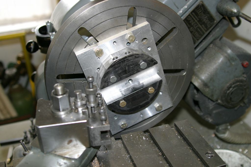
              img_6112.jpg

              Embryo counterweights mounted on the jig plate and centred on the faceplate using a wobbler in preparation for turning the outsides to the 1.760" radius. As pictured the balance was good enough to run at the lathe's lowest direct speed ( 281 rpm ).

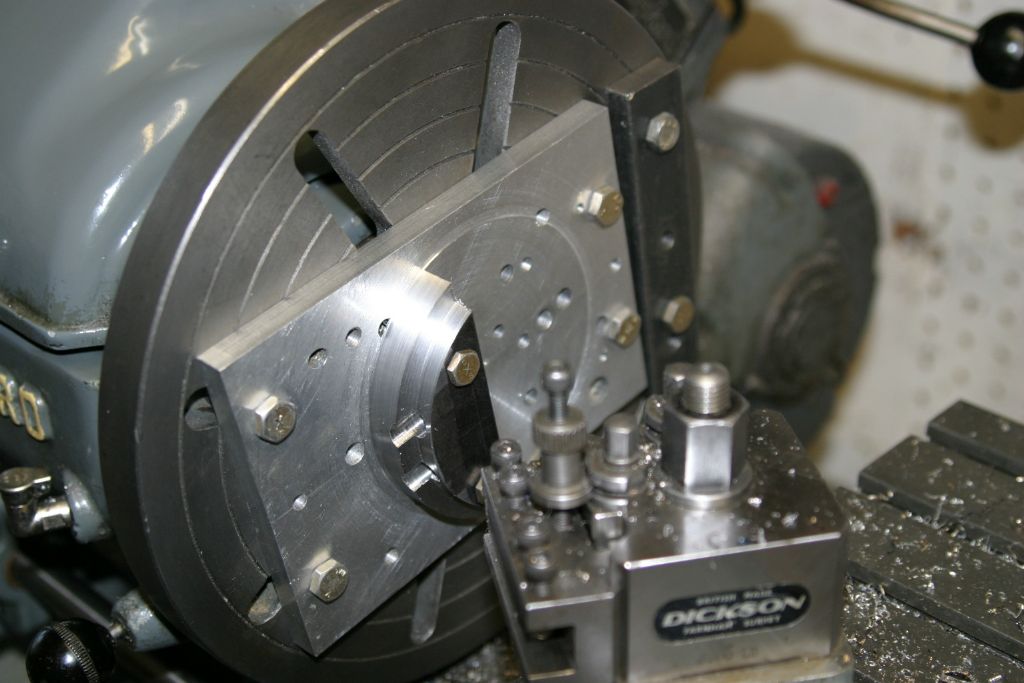
              img_6127.jpg

              The outsides turned to dimension and the .250 x .265 reduced section on the corner of the outer diameter turned to size. Since the two halves are of different thickness, once the thicker one had been turned to .265" deep the thinner was only be .115" deep, therefore the thick one was removed to finish turning the thinner one.

              img_6132.jpg

              Finish turning the recess on the thinner weight, note the extra weight attached to the faceplate to counteract the out of balance.

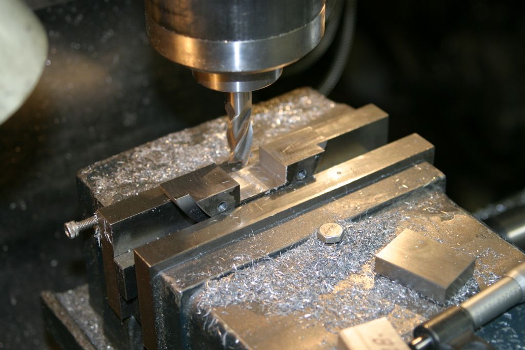
              img_6134.jpg

              Milling out the recess for the end of the crank web, after chain drilling and sawing out the bulk of the waste. The holes for the fixing screws were then spotted through into the webs and the webs tapped 10-32, and the holes in the counterweights opened up to clear the #10 screws ( #10 drill ).

              img_61052.jpg

              The finished crankshaft counterweights with the holes used to fasten them to the faceplate yet to be filled in.

              img_6164.jpg

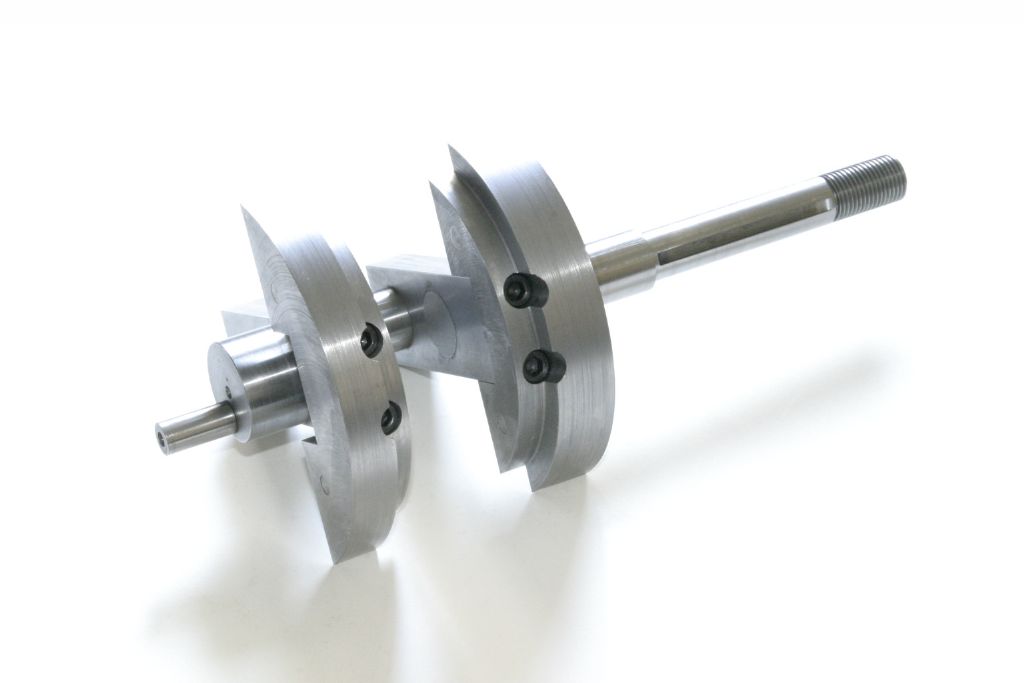
              The crankshaft with the finished counterweights attached.
              After a trial assembly it was found that the two offset con rods foul the edges of the crankcase as they are rotated. This wasn't totally unexpected as there is a note on the crankcase plan "It may be necessary to grind this inside corner of the block for piston rod clearance." So out with the Dremel and a burr to carve away to provide some clearance, after taping over the crankshaft bearings to keep the filings out.

              #537743
              John Purdy
              Participant
                @johnpurdy78347

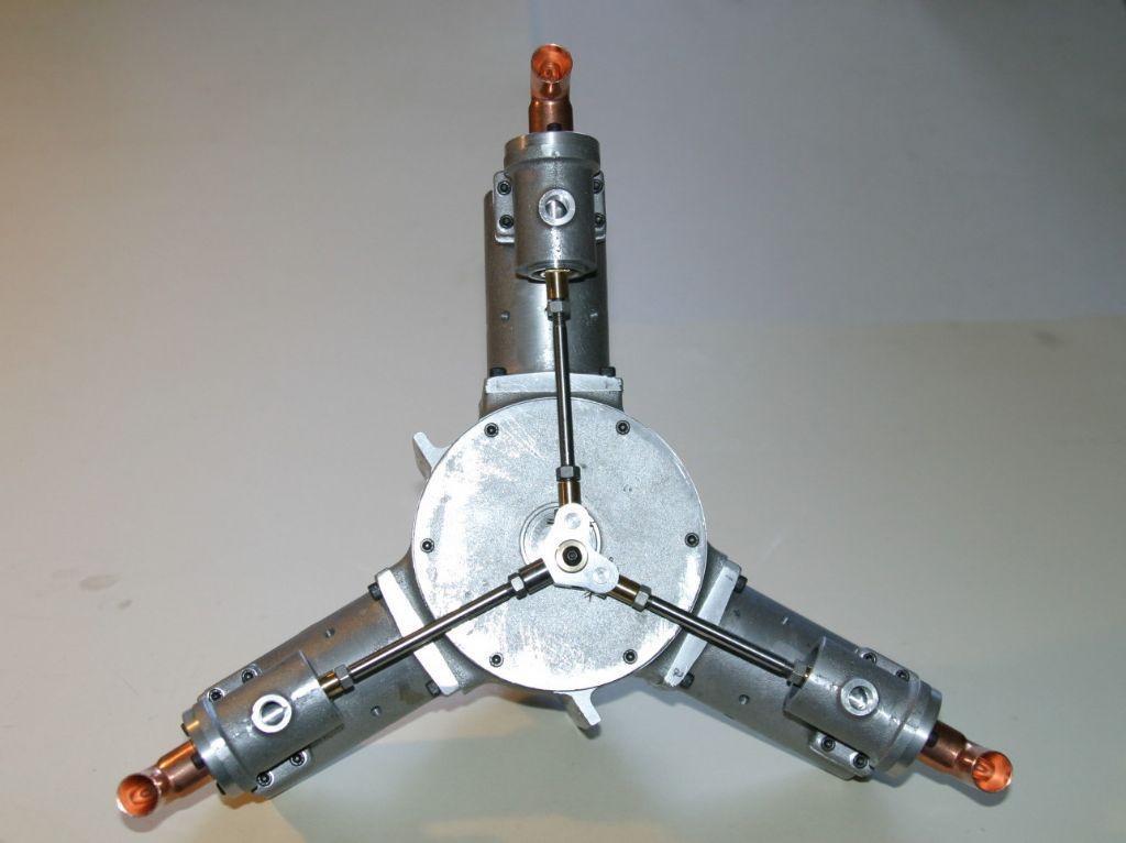
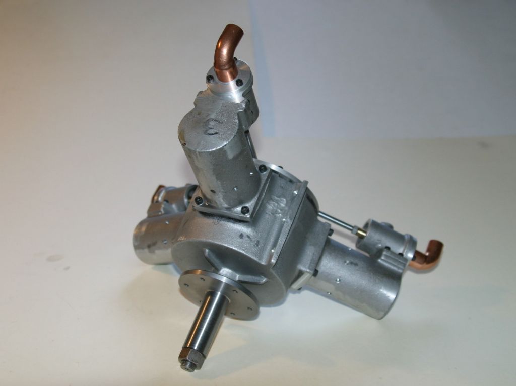
                Here are a couple of pictures of the completely assembled engine, minus the inlet plumbing. I first assembled it without oiling any parts to check the fits and it rotated quite freely with no binding. After oiling everything up and reassembling it its a lot stiffer due to the oil drag but there is no sign of any tight spots.

                img_61171.jpg

                img_61172.jpg

                The next thing is to design a stand for it and to figure out how I'm going to hook up the inlet plumbing so I can put some air to it and see if it runs. First the valve timing will have to be checked as I think things changed when I assembled it, which means taking off the back crankcase cover so I can see when the pistons are at TDC.

                For any one contemplating building one, the plans are nineteen 8 1/2 x 11 sheets stapled into a booklet easily separated for use. I found no dimensional errors on the plans but there are a few missing dimensions, but they could be determined from listed ones. The castings were generally good with some porosity in a few and some had minimal machining allowance, requiring careful setup before machining. As mentioned earlier the cast boss on the crankcase back plate was quite a bit smaller than the required finished dimension.

                #537747
                John Purdy
                Participant
                  @johnpurdy78347

                  While re-setting the valves I found that the piston motion could easily be seen through the drilled exhaust ports in the cylinder and it was easy to judge when the piston was at TDC, so there was no need to take the crankcase back plate off.

                  Also if I was doing it again I would make the valve rod ends that are in the valves longer to give more for a 11/32" wrench to grip to hold the valve from rotating as the jam nut is tightened. As it is, it only sticks out of the bottom of the valve slightly less than 1/16". The plans call for the head to be .388" long with the hole for the wrist pin .188" from the end. I would increase the .388" to .588" keeping the .188" the same (the valve rods would then have to be shortened by .200" to compensate ). I found that the valve wrist pins have to be very close to 90 degrees to the plane of the swing of the valve rods or everything jams up as the eccentric goes around, hence the need to ensure the valve doesn't rotate while tightening the jam nut.

                  Edited By John Purdy on 03/04/2021 03:49:47

                  #539073
                  John Purdy
                  Participant
                    @johnpurdy78347

                    img_6189.jpg

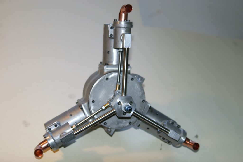
                    Here's my solution for the inlet plumbing, made from some pieces of aluminum and 3/8" OD tubing. Inlet fitting is a 1/4' flare fitting.
                    At 10 PSI it just ticks over once the prop hub is give a little twist. at 40 PSI it runs at just under 500 RPM and at 60 it's ~780 RPM. It doesn't want to self start at any pressure, but I think the valve setting is off, as when just ticking over the exhaust sound is not regular. The exhaust note is quite explosive, as if there is a fair amount of compression before the exhaust opens. It uses a lot of air, at 60 PSI it certainly drains my 20 gal. compressor tank quickly (starting at 120 PSI).

                    So that's it, finished (except painting??? ). Now I guess I need to fabricate a stand for it and think about a prop !

                    #539081
                    gary
                    Participant
                      @gary44937

                      well done john, looks good without paint ?

                      #539106
                      DiogenesII
                      Participant
                        @diogenesii

                        Nice job, John – the inlet pipework looks much more in proportion to the whole. ..I rather like it without paint, too – tho' it always feels a bit cheeky to be commenting on the finish of another's engine..

                        Please keep us updated on the prop and other bits & pieces, it's an enjoyable build…

                        #547611
                        John Purdy
                        Participant
                          @johnpurdy78347

                          Now that the this engine is finished except for the stand ( still haven't found any material for that yet ), the next project will be a Red Wing hit and miss, castings are ordered and awaiting delivery.

                          #547857
                          gary
                          Participant
                            @gary44937

                            hi john, are we going to get a build on the redwing ?

                            #547859
                            not done it yet
                            Participant
                              @notdoneityet

                              Finished? Pleeese lets see/hear it running! I’ve enjoyed watching your progress on the engine.

                              At first look, I thought the red wing might be a plane to fit it in.🙂

                              How would the steam be generated for it? I don’t expect they had to carry half a tonne of coal for a long distance flight.🙂

                              What speed, and diameter, prop would be required?

                              #547931
                              John Purdy
                              Participant
                                @johnpurdy78347

                                Dave

                                I haven't decided. Apparently there have been quite a few build threads around but I don't think there has been one on this forum. What do people think?

                                NDIY

                                Sorry, there won't be a video of it running as I don't have any way of making one.

                                There won't be an aircraft either as it is too big for a model and too small for a real one!

                                The original swung a 4 bladed, 50 1/2" dia. prop at 2000 RPM generating 70 HP at 300 PSI steam pressure. Mine runs at ~800 RPM at 60 PSI. At that speed it is starting to vibrate, so to get anywhere near 2000 the crank balancing would have to be changed.

                                The write up on the original makes no reference to the steam generator, but to develop 300 PSI within reasonable weight constraints I suspect it would have been a flash steam unit fired with liquid fuel.

                                John

                              Viewing 14 posts - 51 through 64 (of 64 total)
                              • Please log in to reply to this topic. Registering is free and easy using the links on the menu at the top of this page.

                              Advert

                              Latest Replies

                              Home Forums Stationary engines Topics

                              Viewing 25 topics - 1 through 25 (of 25 total)
                              Viewing 25 topics - 1 through 25 (of 25 total)

                              View full reply list.

                              Advert

                              Newsletter Sign-up