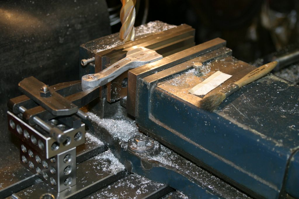
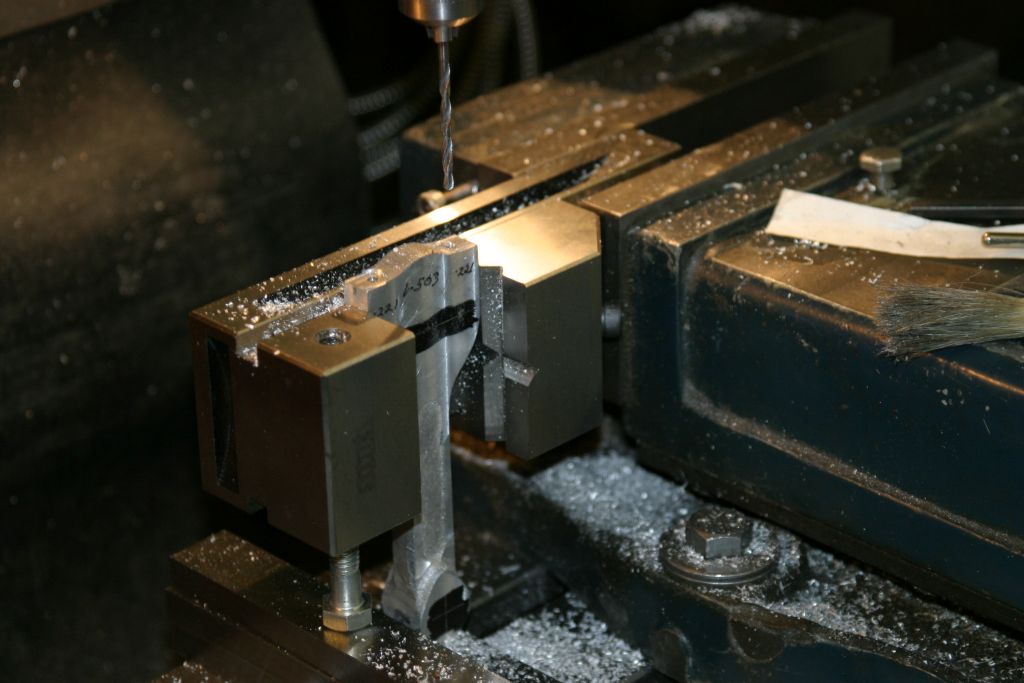
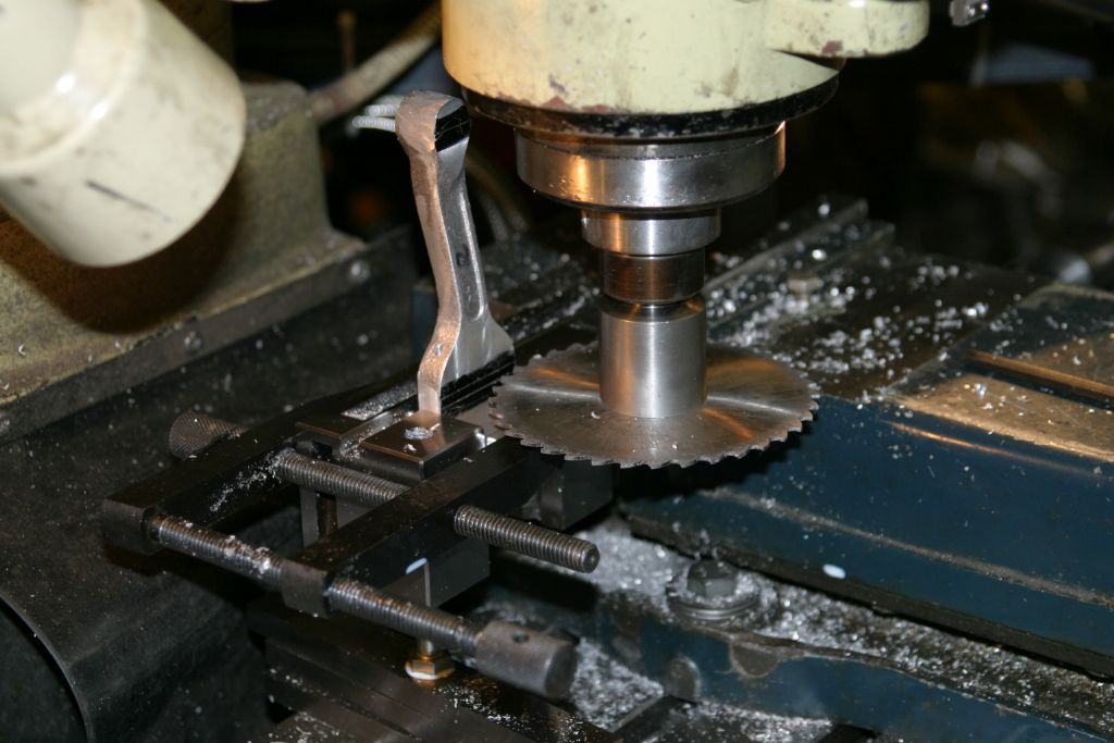
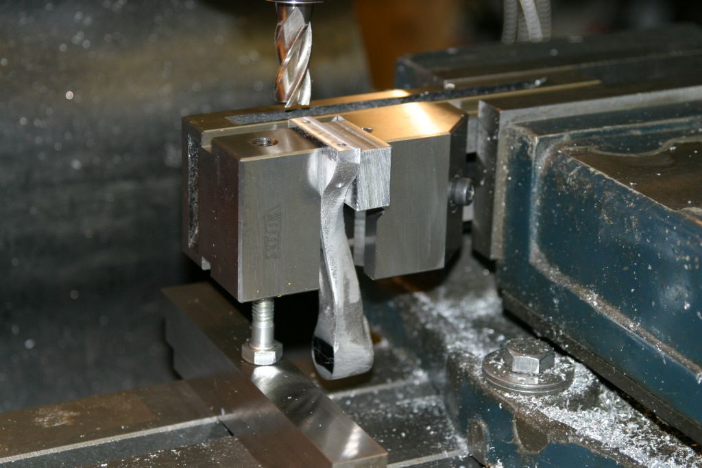
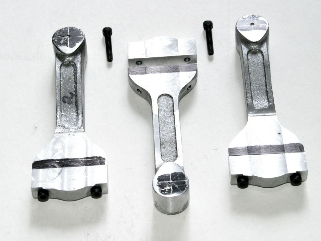
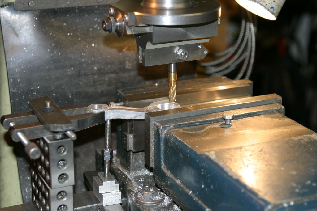
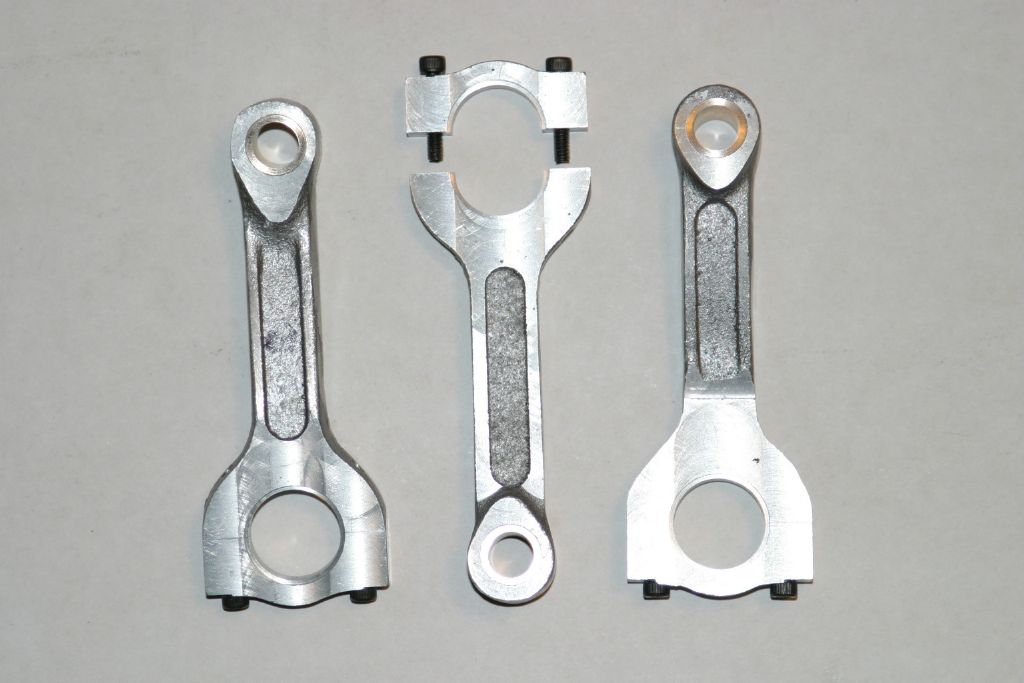
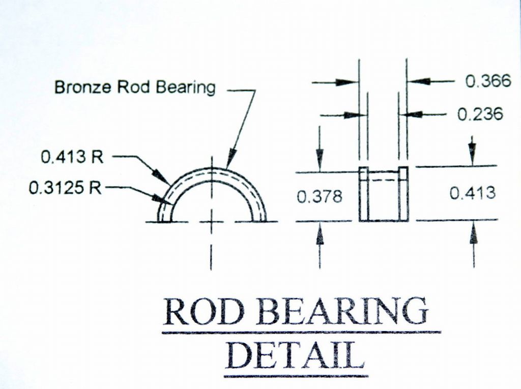
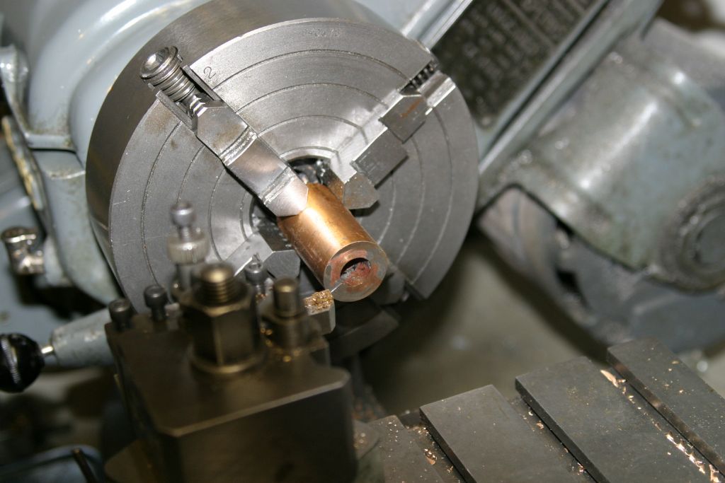
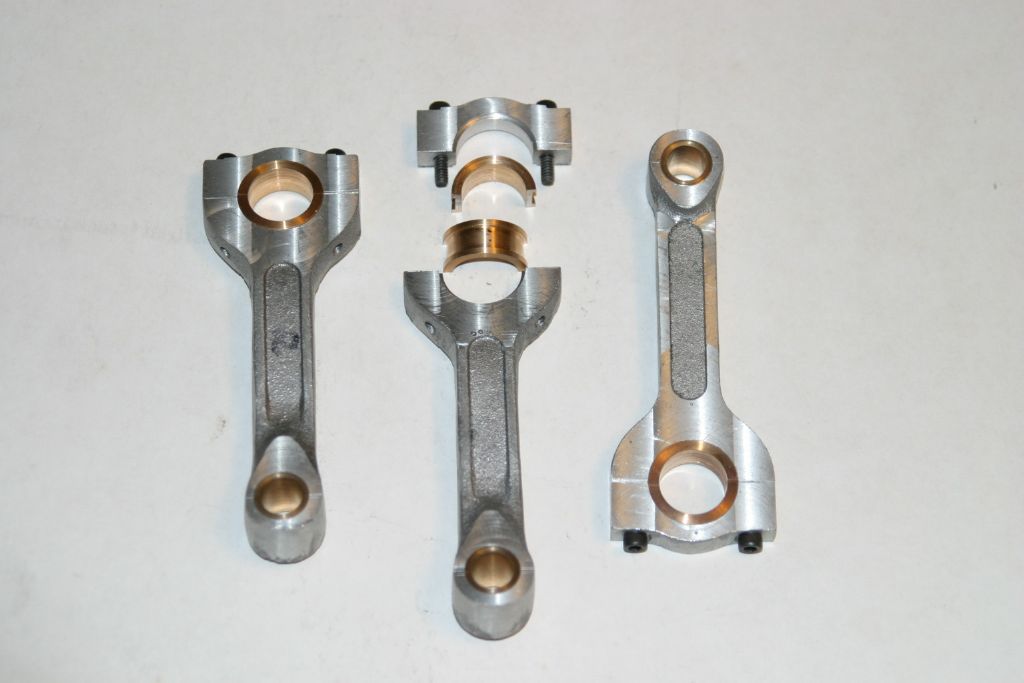
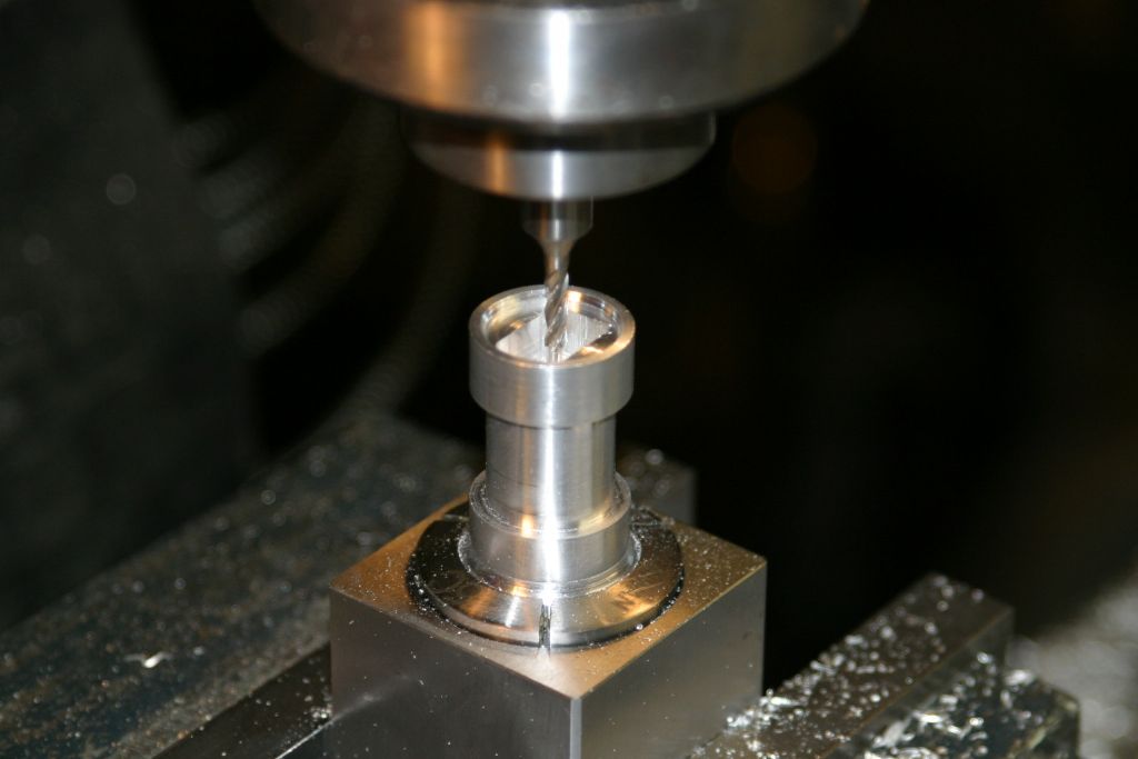
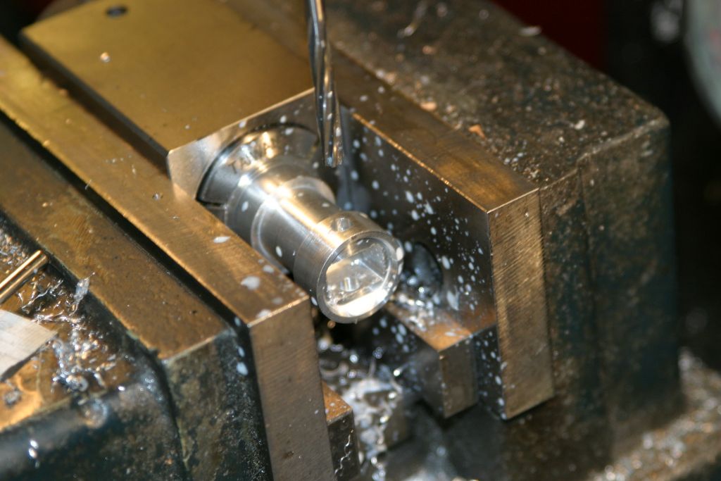
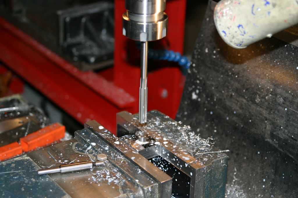
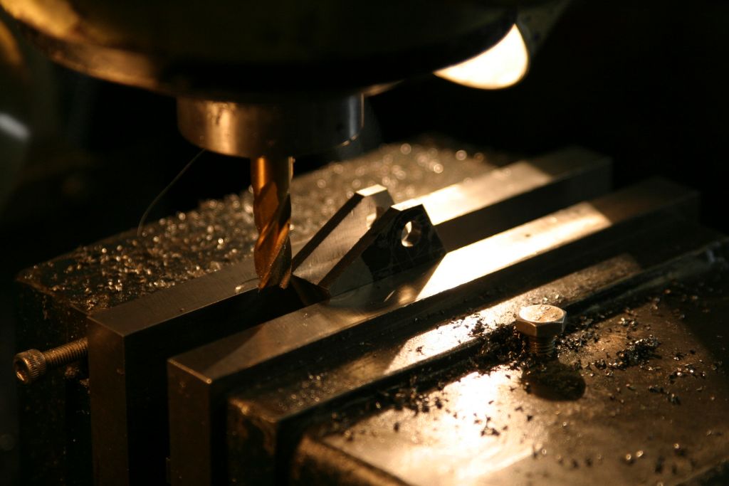
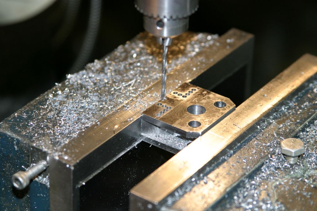
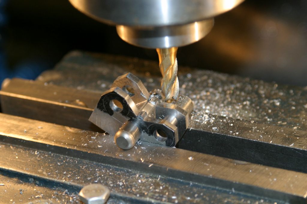
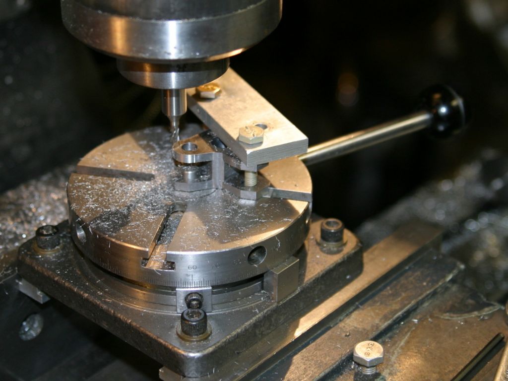
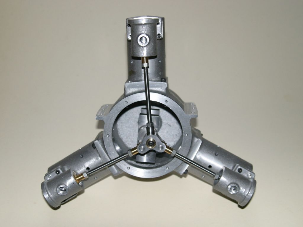
The big end bearings started as a 2" length of 1" dia. bronze rod. It was first drilled through 1/2" and then using a 1/32" slitting saw was split longitudinally in half. Each half was then mounted in the mill vice, with the sawn faces parallel to the table, and cleaned up with an end mill, as I have found a thin slitting saw tends to wander and seldom cuts straight. The two halves were then tinned with 50/50 SnPb solder, clamped together and heated to sweat them together.

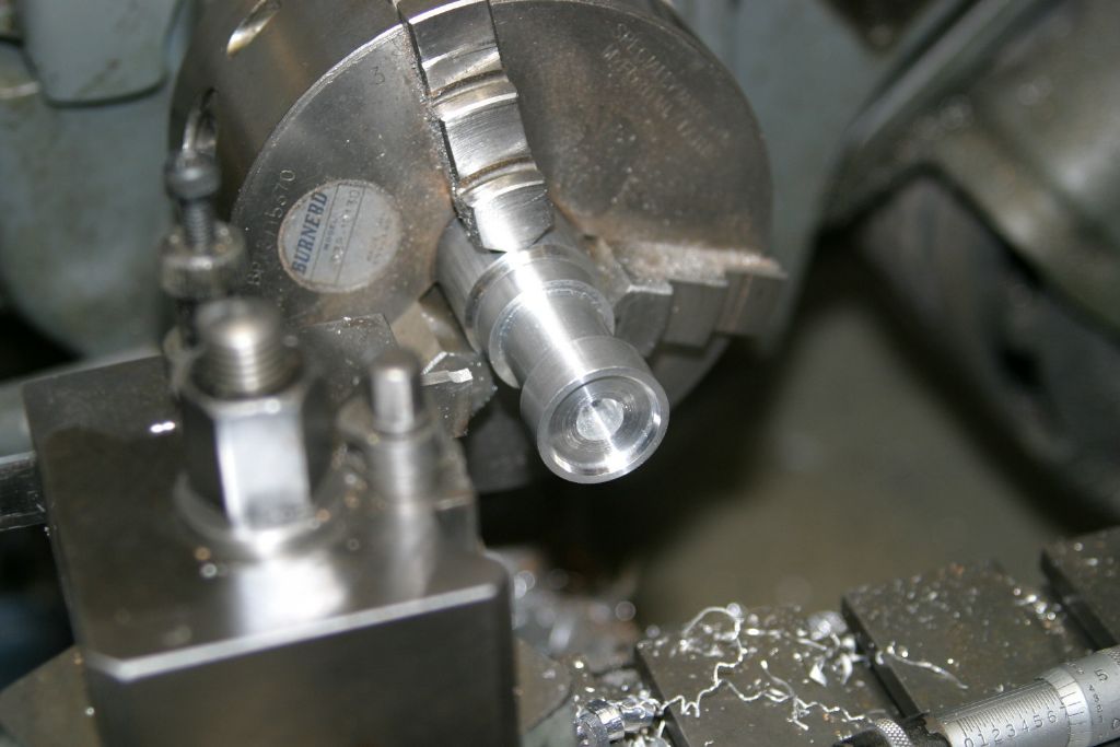
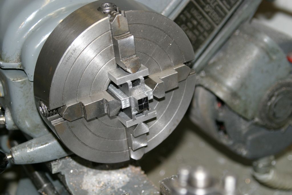
The bar, now decidedly oval due to the material removed in splitting it, was mounted in the 4 jaw and "centred" using a dial indicator. When I say "centred" I mean the chuck was adjusted so that the readings each side on the split line were the same and the two at 90 deg. were the same. In other words the two high points gave the same reading and the two low points were also the same. This should ensure that the split line is in the middle of the finished bearing. Once set, the OD was skimmed to clean up to be round as far as the chuck jaws.

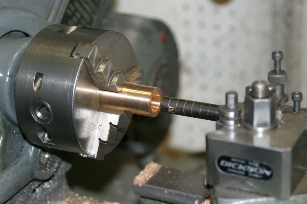
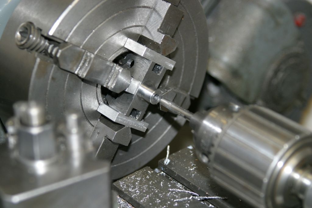
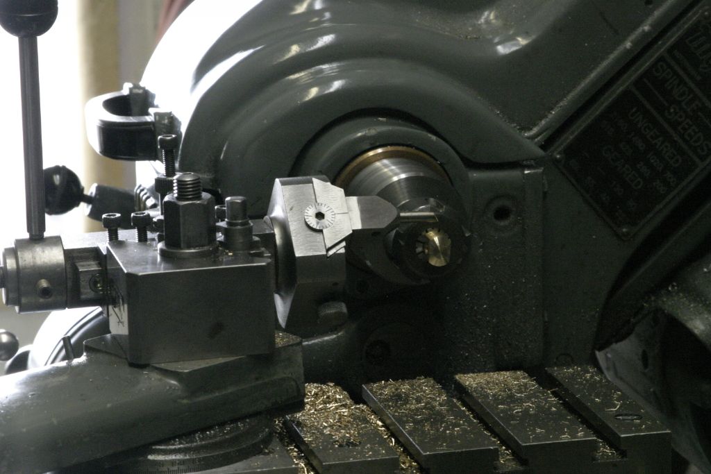
Transferred to the 3 jaw, with the other end (still oval) outward, it was turned down to the same diameter as the first. The centre was then bored out to .656" for a running fit on the crank pin.

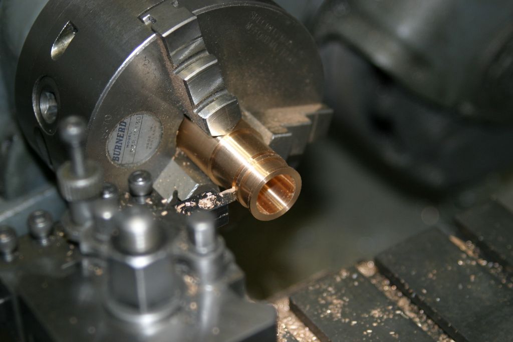
After boring for the crank pin, the OD was turned to .825" for a running fit in the recesses in the sides of the con rods and then, using a small cutoff tool, the groove was cut and the bearing cut off slightly over length.

After all 3 were turned they were mounted one at a time on an expanding mandrel and the cutoff end faced back to give an overall length of .366". They were heated with the torch to separate the two halves and once cool the excess solder was removed by rubbing on a fine file. A trial fit on the crank pin found they all fit and rotate but are a little tighter than I would like so will require some easing.
 John Purdy.

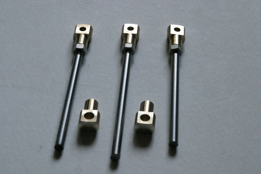
 to raise/support them to/at a suitable height?