Three Cylinder Steam Aero Engine
Three Cylinder Steam Aero Engine
Home › Forums › Stationary engines › Three Cylinder Steam Aero Engine
- This topic has 63 replies, 9 voices, and was last updated 31 May 2021 at 18:31 by
 John Purdy.
-
AuthorPosts
-
7 November 2020 at 21:46 #505900
 John PurdyParticipant@johnpurdy78347
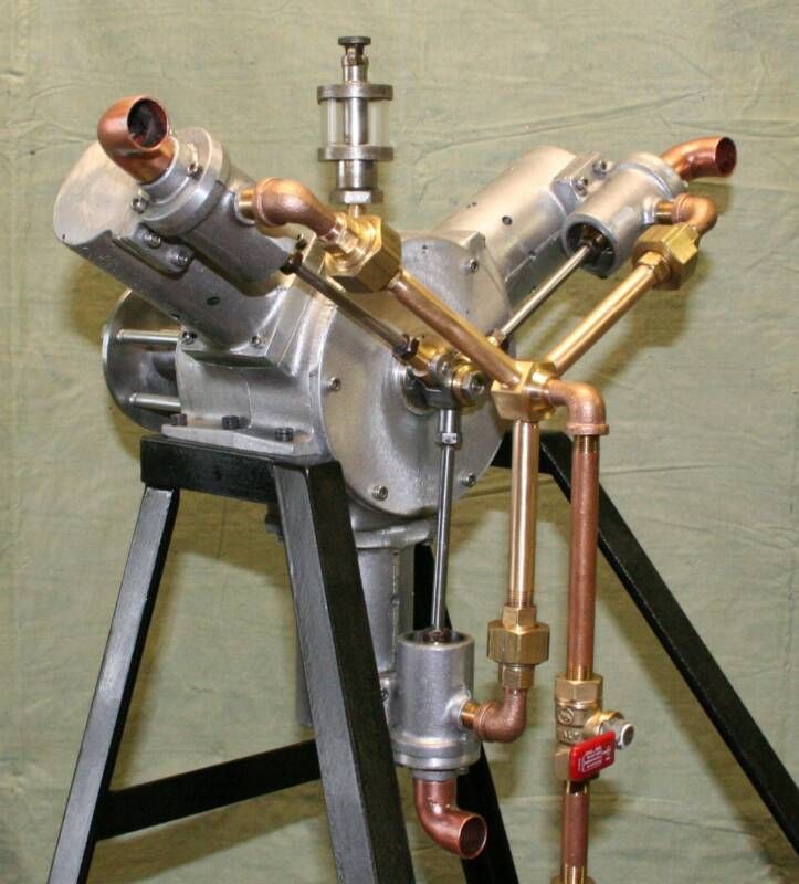
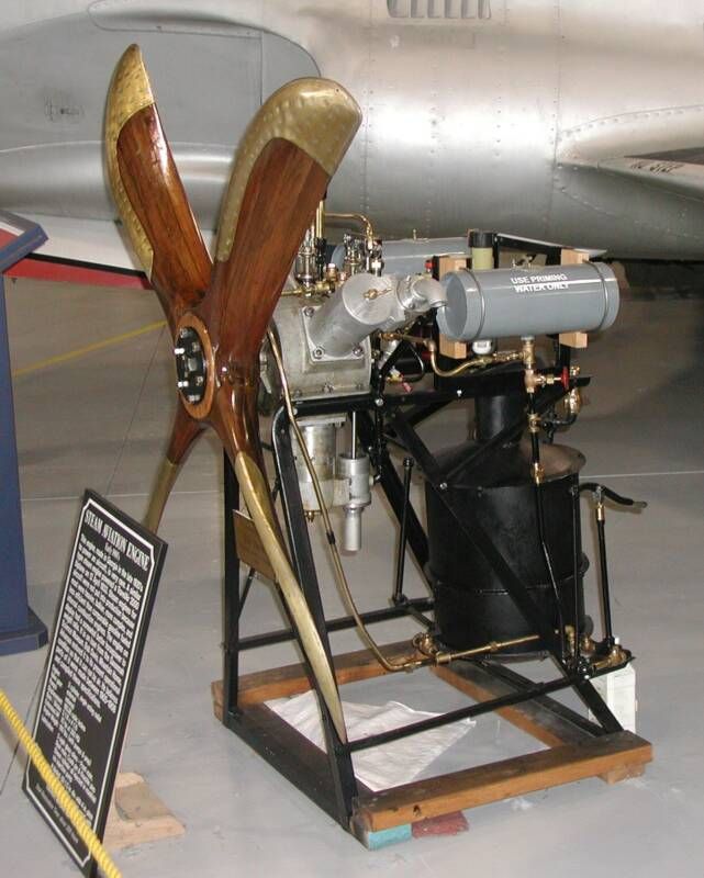
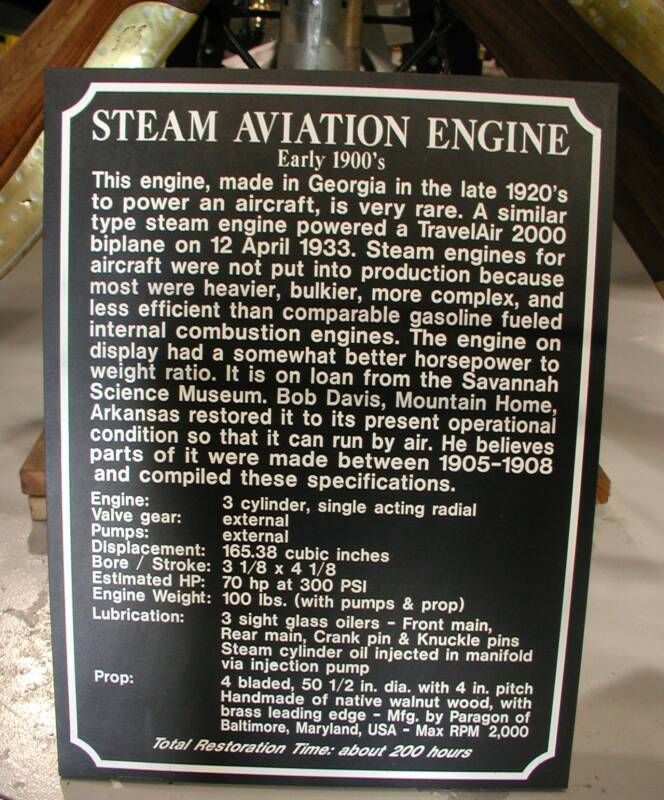
At the beginning of August there was a post here asking if anyone had built the steam aero engine from Meyers Engine Works. By coincidence I had just ordered the castings for it and have now started to build it. As an introduction here are some pictures, with permission of Meyers Engine Works, of both the model and the original engine including a write up about the original.
The model has a 1.5" bore and a 2" stroke.
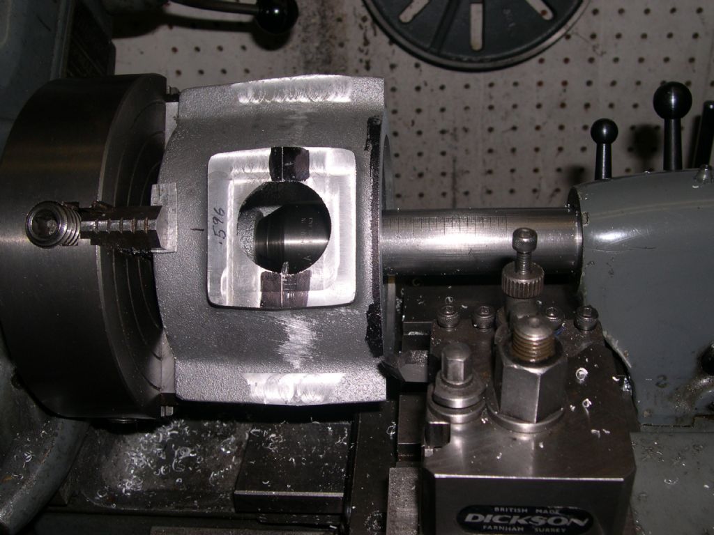
I decided to start by doing some preliminary machining on the crankcase.
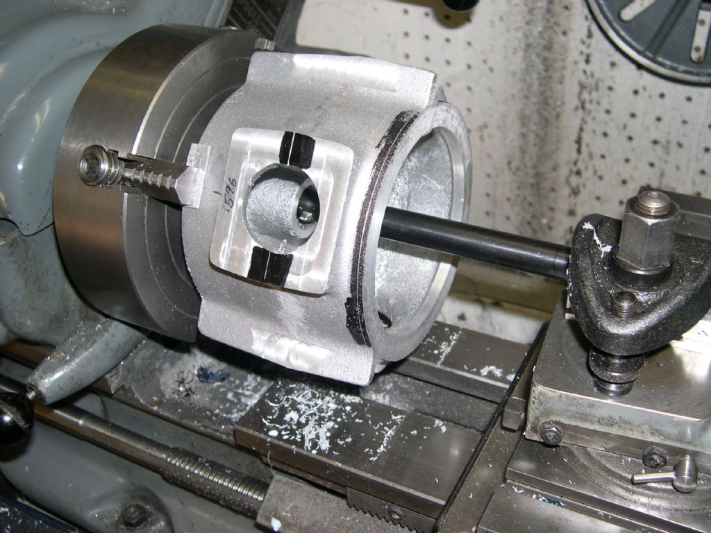
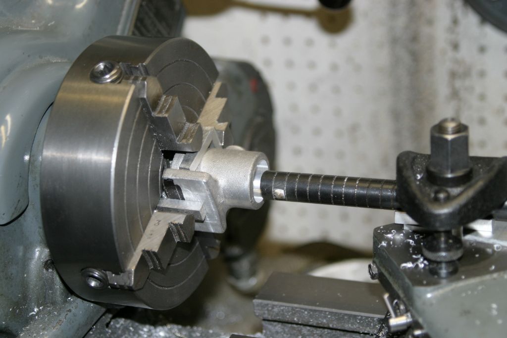
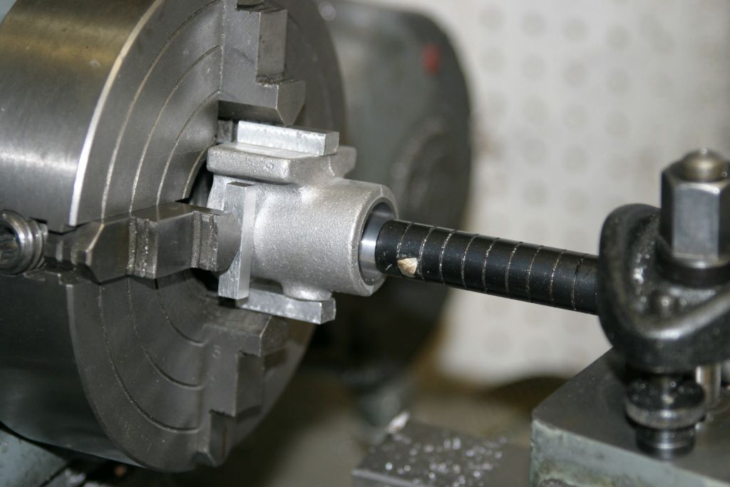
Set up in the 4 jaw to drill out the front crank bearing boss to 1/2" and clean up the rear cover face to act as a datum for further ops. Note the use of the tailstock centre in the crank bearing boss to give added support due to the large overhang and limited grip in the chuck.
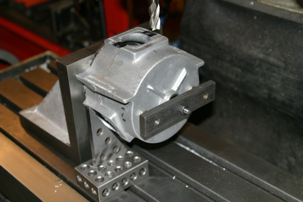
Mounted on an angle plate on the mill by a rod through the front bearing hole to a bar across the casting so that the clamping force was on the outer walls of the case and not the centre. In this setup the cylinder mounting faces were skimmed to true them up and to be at 120 degrees to each other. They are called for to be 2.400" from the centre line of the crank but I haven't yet quite figured out how I am going to measure this.
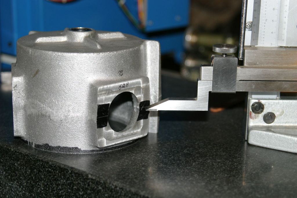
Marking out the longitudinal centre of the cylinder mounting bosses by halving the distance between the top and bottom of the cast bosses. This was done for all three and an average used to mark the centres.
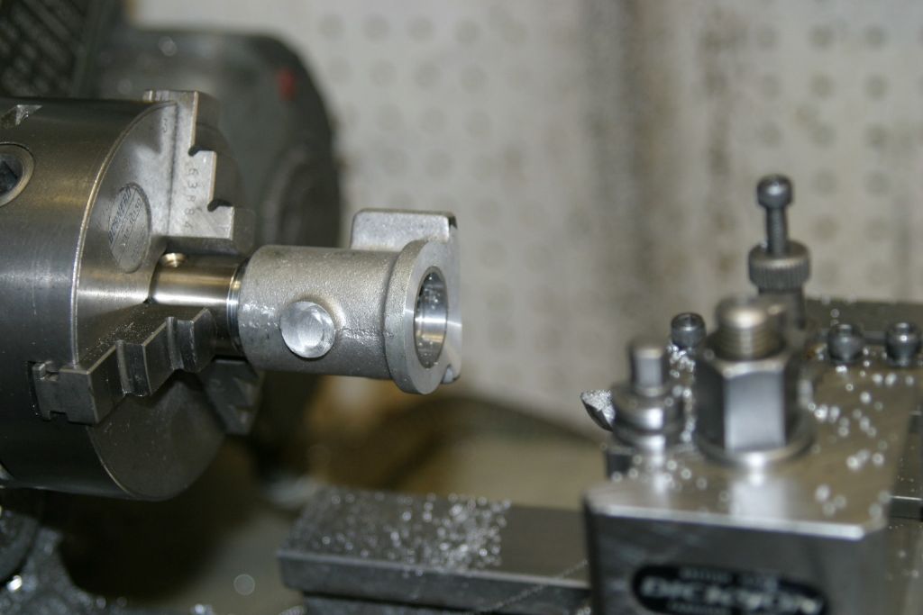
The casting was then returned to the 4 jaw as in the initial setup, to bore the front boss for a press fit for the crank bearings ( two 5/8"x13/16"x1/2" needle bearings) and to machine the inside face of the bearing boss back to finished dimensions. The rear face was then machined to the finished dimension of 1.350" from previously marked cylinder longitudinal centre line. At the same time the locating recess for the rear cover was machined thus maintaining concentricity, as the rear crankshaft bearing is in the rear cover.
John
Edited By John Purdy on 07/11/2020 21:50:04
Edited By John Purdy on 07/11/2020 21:50:39
7 November 2020 at 21:46 #3424 John PurdyParticipant@johnpurdy783477 November 2020 at 22:00 #505904
John Haine
Participant@johnhaine32865Interesting! I think F J Camm described a flash steam power plant for model aircraft back in the 50s – I think there was a small book about it and the original publication was probably Practical Mechanics.
7 November 2020 at 23:02 #505914not done it yet
Participant@notdoneityetThey are called for to be 2.400" from the centre line of the crank but I haven't yet quite figured out how I am going to measure this.
‘Twill be easy enough when you replace that bar through the middle with another of known diameter, sat in its bearings or bearing seats?=
I like the idea of a steam aeroplane – perhaps not the most useful of ideas, but when the oil runs out…🙂
That is some operating steam pressure! A good job it is a radial, and not a rotary, engine – the usual type in the early 1900s?. I look forward to developments.
8 November 2020 at 05:33 #505930 garyParticipant@gary44937
good pictures john, looking forward to watching this build.
8 November 2020 at 07:04 #505934 JasonBModerator@jasonb
Looks an interesting build, as to the 2.4" dimension while you have it running true in the lathe use a height gauge off the cross slide set 2.4" above ctr height to mark the dimension. Alternatively if you have a rotary table or dividing head set it up on that then you can set tool 2.4" above axis and also use that to set out your 120deg spacing.
8 November 2020 at 19:24 #506078 John PurdyParticipant@johnpurdy78347
I have pressed the front crank needle bearings in, and to machine the cyl. mounting faces to the pre-requisite 2.400" from the crank centre line, a piece of 5/8" drill rod in the bearings will provide a reference for the centre line. The problem is how to I hold it on the angle plate seeing as now the central hole is no longer available?
Jason I hadn't thought of using a rotary table but that sounds like a good solution. Mounted vertically on the mill and the crankcase clamped centrally on it using the "T" slots, the 2.400' dimension could be measured with a height gauge on the mill table. The holes for the cyl. liner skirts would be bored at the same time.
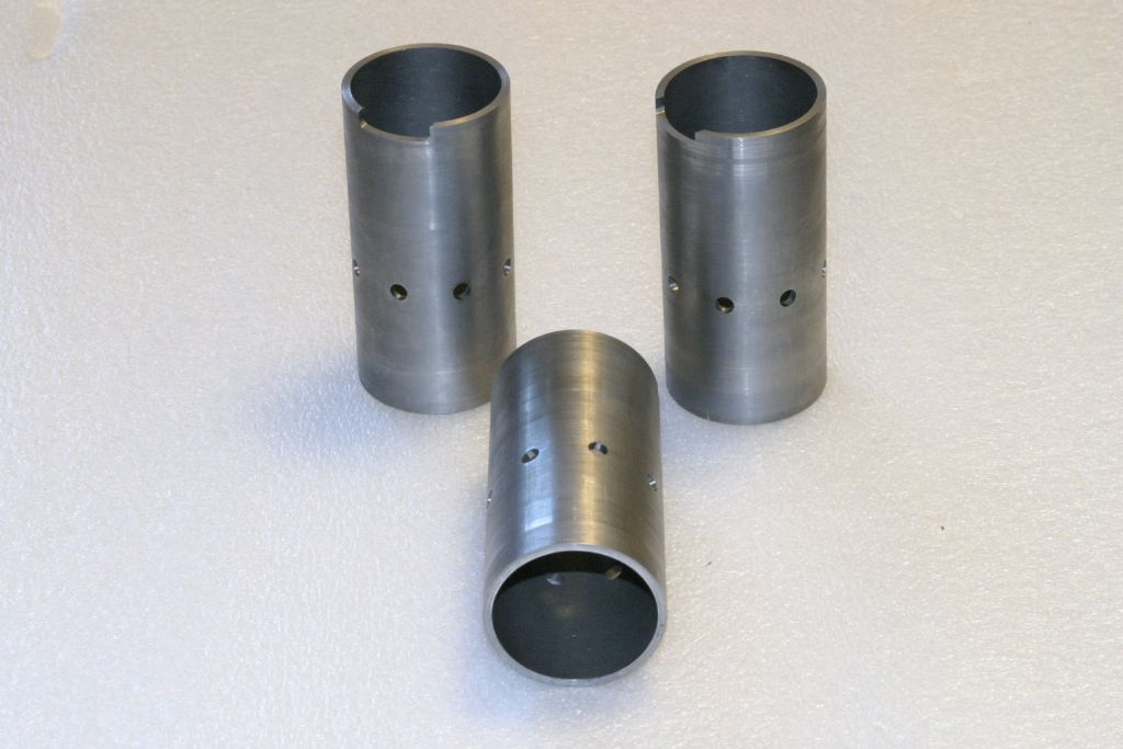
So the next job is the cylinders and their steel liners. The cylinders are cored alu. castings and the liners are 3 lengths of what look like schedule 40 seamless hydraulic tubing the ID of which is just shy of 1.500" and has a very good smooth surface. First job will be to give the bore a short hone to see how round and true it is, or if it will require boring first.10 November 2020 at 19:18 #506545 John PurdyParticipant@johnpurdy78347
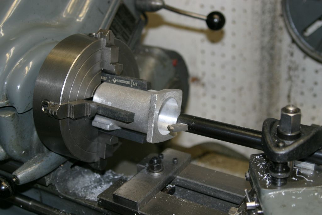
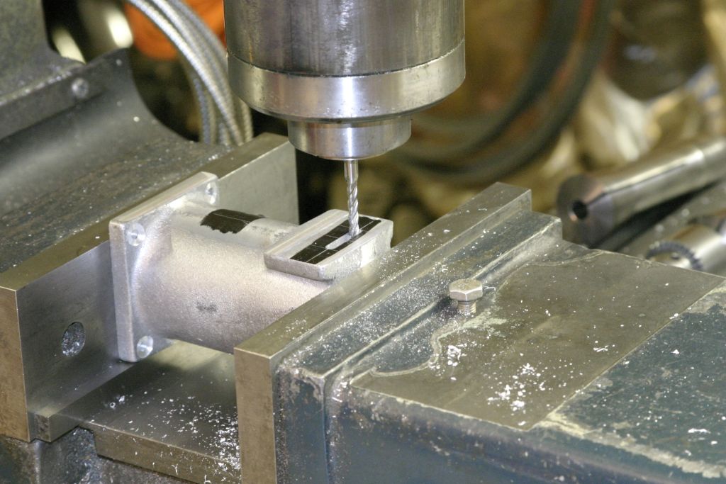
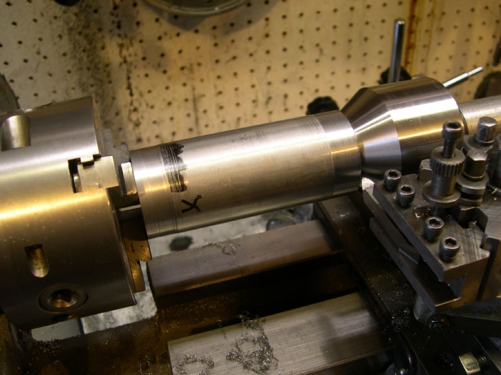
The first operation on the cyl. castings was to mount them in the 4 jaw, flange outward, and roughly true them but ensuring that they were parallel to the lathe axis and not wobbling. The flange was then faced to just clean up. Moved to the mill they were clamped in the vice with the flange on the fixed jaw and the square pad at the other end leveled as best as possible. This pad was then milled flat to remove the draft from the pattern since the mould line runs through the centre of this pad. The same was done to the edge of the flange, in both cases only sufficient was taken off to leave a witness of the original cast surface at each end.. It was then turned over and with the previously machined flange on a parallel the opposite flange was done. All 3 were done to this stage.
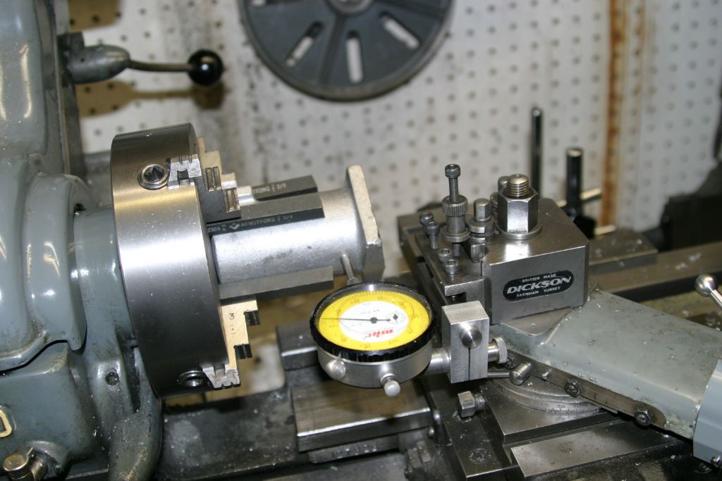
Back to the lathe in the original setup it was clocked true on the outer cast surface . Note the blank 3/8" tool bits acting as jaw extenders for a more secure hold.
Once trued up as best as possible on the cast surface it was bored for the liner. Since this is a blind hole the boring bar was first run in clear of the outer wall till the bit touched the top end of the cored hole which is concave dome shaped. The stop across the bed shears seen in the picture was then pressed up against the front edge of the saddle and locked to the bed as a depth stop for the boring. When the bore was within about .050" of size the depth from the flange was measured and as it was less than the 3.250" required, the stop was move back and the bore was deepened till it was about .025" over to allow the flange to be skimmed back to give the required 3.250 depth, thus ensuring the bore and flange are at 90 degrees. With the boring bit against the top of the bore the stop was re-positioned against the front of the saddle and the bore finished to the called for 1.690" by 3.250" deep.
The casting was then mounted vertically in the milling vice and the bore centred under the spindle. Using coordinates, the four mounting holes were drilled tapping size for the 8-32 hold down screws. The top face was then counterbored for the screw heads using a home made reverse counterbore.
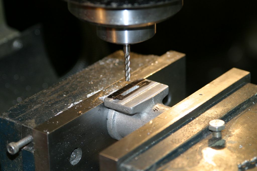
Back to the mill in the same setup as first used, the .140" x .750" slot for steam admission was milled. This was first marked out on the surface plate so the top of the slot coincided with the top of the bore. It was first drilled with a series of 1/8" holes then cleaned up to dimension with a 9/64" long series end mill.
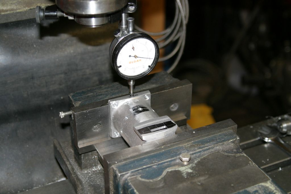
This face, where the valve body bolts, was initially only just cleaned up and it now had to be milled back to finish 1.055" from the cylinder bore centre line. Since the machined edge of the flange and this pad were machined parallel previously, this edge could be used to establish this dimension. The distance from the inside of the bore to the top of the flange was measured and added to half the bore diameter to give the flange to the cylinder bore centre line distance.
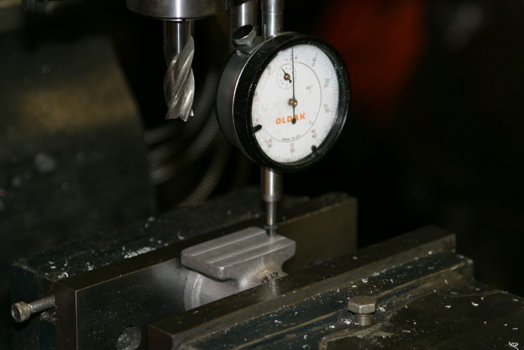
Using a dial indicator to measure the difference in height of the flange and the valve body pad, the pad was milled down to leave it 1.055" from the cylinder centre line.
14 November 2020 at 17:58 #507511 John PurdyParticipant@johnpurdy78347
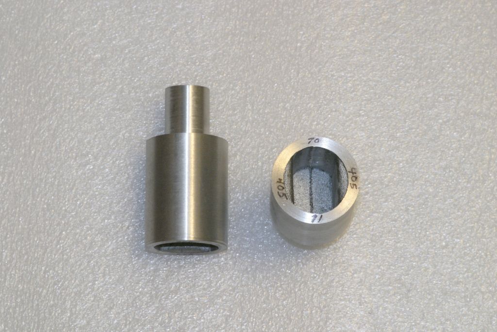
The bores of the tubing for the liners were pleasantly true and round as it only took a couple of minutes of lapping with 220 SiC grit to get a continuous matte finish all over. Thankfully no need for an initial boring. They were then given a further lapping with 320 grit, and all finished up at 1.5075" in diameter.
Next to turn the OD to finished diameter the liner was held between the 3 jaw and a bull nose rotating centre and a skim was taken off the OD for a short distance at the tail stock end. It was then reversed and the chuck adjusted till the skimmed section was running true. The OD was then turned down to the finished dimension of 1.686" to give clearance for the retaining compound fastening it into the cylinder jacket. The liners were then cut down and the ends cleaned up to their finished length of 3.450".
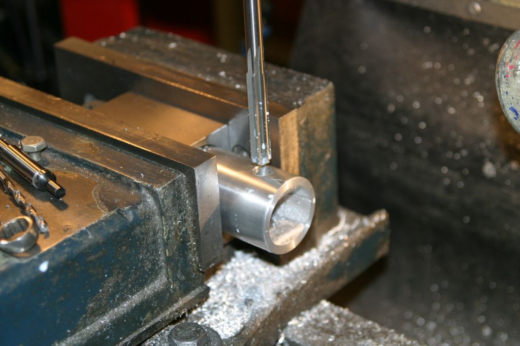
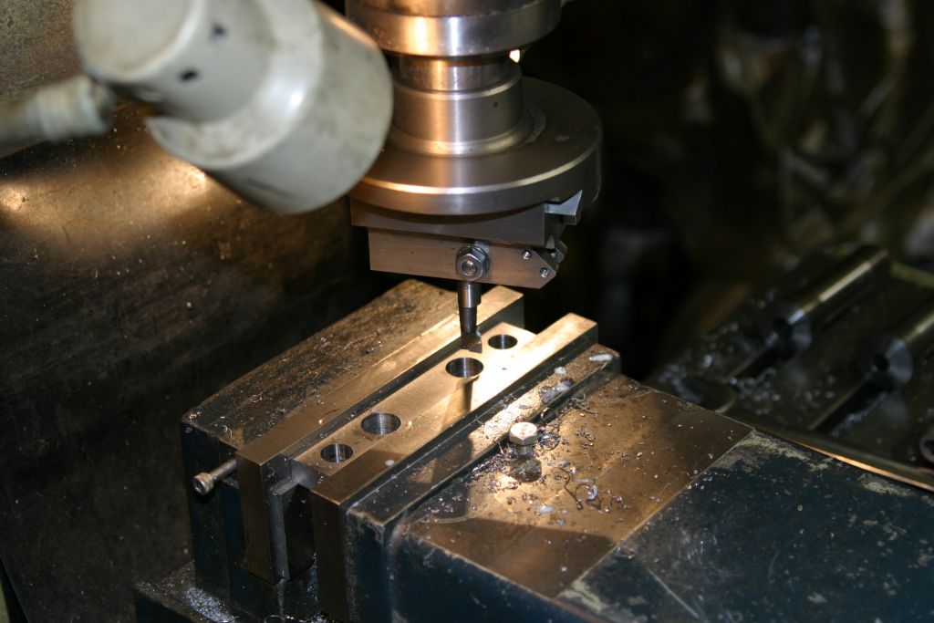
The next job was to hold the liner by the ends in the mill vice, and using an end mill, cut a .140 x .750" recess in the end to clear the steam admission slot in the cylinder jacket.The cylinder exhaust ports are eight 3/16" holes equally spaced around the the cylinder 1.280" from the bottom.
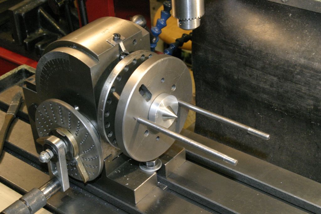
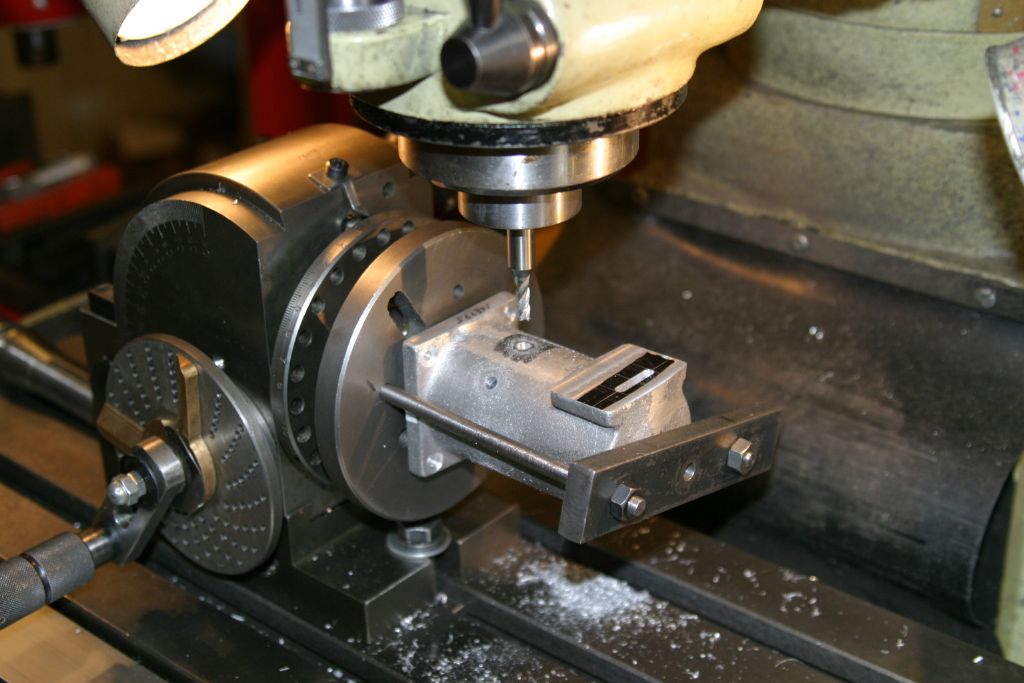
To drill these, a locating ring was turned up to centralize the cylinder and liner on the dividing head.
The liner was slid into the cylinder, and ensuring the the recess it the top was lined up with the slot in the cylinder, it was clamped to the dividing head by a bar across the top. The exhaust ports were then made. First spotting the holes, then drilling .015" under-size and finishing by plunging through with a 3/16" end mill. Doing it this way I hoped to raise the minimum of a burr on the inside. Once done the liners were removed and a couple of minutes on the lap removed the small burrs that the drilling created. The lap was cleaned up and a further lapping with 500 grit finished the bores. Just left to do is to fasten the liners into the jackets with retaining compound.
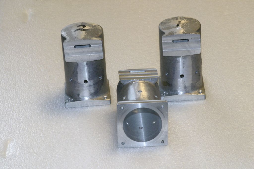
The finished cylinder jackets, except for drilling and tapping for the valve bodies.
The finished cylinder liners.
27 November 2020 at 05:08 #510102 John PurdyParticipant@johnpurdy78347
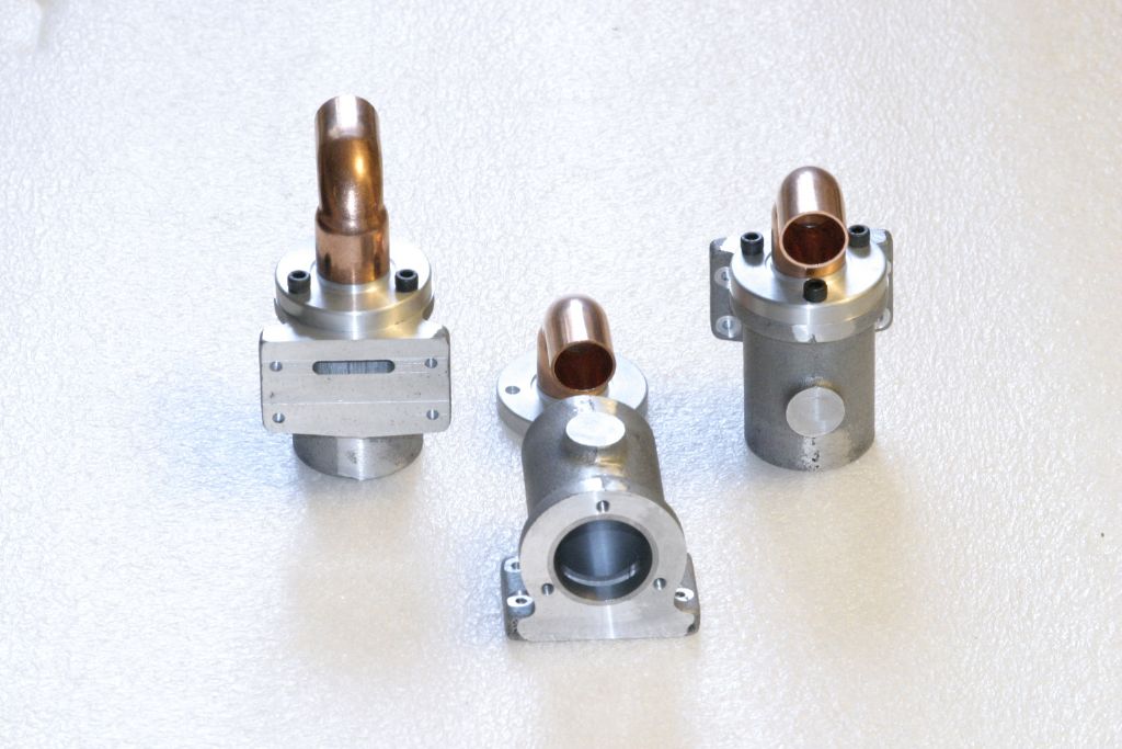
The valve bodies are aluminum castings very similar to the cylinder jackets except that they are smaller and open at the top. The first operation was to grip in the 4 jaw with the top flange outermost, truing as best as possible on the outer cast surface. The face of the flange was cleaned up to a flat surface to act as a datum for the next operation. It was then held in the mill vice with this face on the fixed jaw and with the face of the cylinder mounting flange set as horizontal as possible the mounting flange was milled to just clean up. It was then turned over, and with the mounting flange on a parallel the boss for the steam inlet was milled flat and to the same height as the top flange. The liners for the valve bodies are supplied as a ~6" length of nominal 1" diameter seamless hydraulic tubing. The tube was chucked in the 3 jaw and with the outer end supported by a rotating centre in the bore, the OD was skimmed to clean up, finishing at .990". The three liners were then cut off over length and the ends cleaned up.
With the body back in the 4 jaw, top flange next to the chuck, it was pressed back on to a parallel and trued as best as possible on the outer surface. It was then bored out to .992" for the liner. The liners were then fastened into the body with high strength retaining compound. I had hoped to true the bores of the liners up with just a short lapping as I did for the cylinders but no such luck, they were too far out of round.
So back to the 4 jaw to bore them out to true them up. When setting up in the 4 jaw they were trued using the bore, ensuring that they were as true as possible both radially and longitudinally. They were then each bored out to .882.
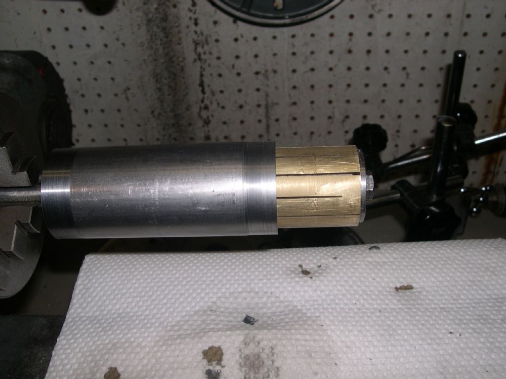
Set up on an expanding mandrel to skim the top flange to ensure it is at right angles to the bore. This flange will be used as the datum when finishing the mounting face to dimension, thus ensuring that it is parallel to the bore. Reversed on the mandrel, the bottom end was turned back to give an overall length of 1.750" as per the plan.
Back to the mill, setting the mounting face parallel to the table, to mill the face back to the plan dimension of .860" from the centre of the bore, ready for the next operation; cutting the .140" x .75" steam admission slot to mate with the one at the top of the cylinder.
Having first marked it out, the steam transfer slot was milled out with a long series 9/64" end mill. The same sequence of drilling and milling was used as for the cylinder jackets.
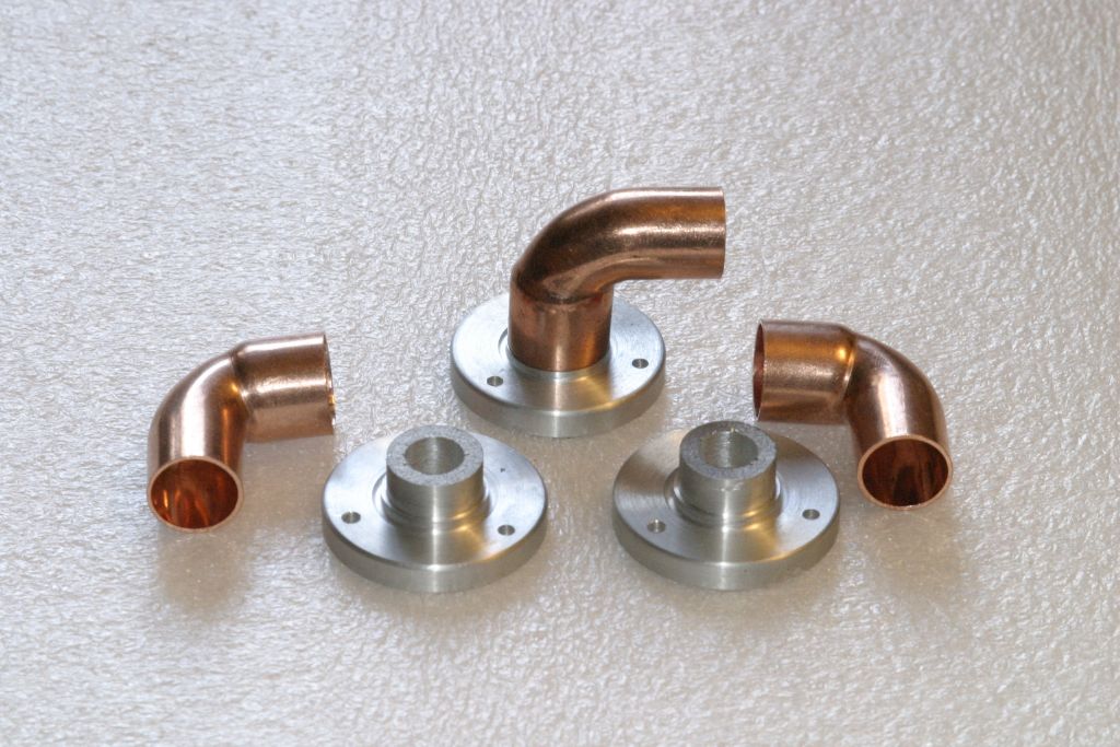
The valve body heads are simple castings requiring only lathe work to bring to dimension and then drilling for the fixing bolts and the exhaust port. Exhaust stubs are 1/2" copper plumbing 90 degree street ells.
Edited By John Purdy on 27/11/2020 05:13:10
28 November 2020 at 23:46 #510528 John PurdyParticipant@johnpurdy78347
Using the expanding mandrel on a "V" block to hold the valve body with the face vertical to mark out the mounting holes symmetrically around the bore centre line.
The valve bodies finished with the mounting holes drilled and counterbored, and the top flange tapped for the heads. The holes in the bosses for the steam inlet on the front still have to be drilled and tapped. Plans call for them to be 1/8" NTP, but I haven't decided what to use for the elbows, so till that is settled they will have to wait, along with the final lapping to remove any burrs from the slotting and drilling/tapping.
Now on to finish the pistons.
Edited By John Purdy on 28/11/2020 23:47:40
29 November 2020 at 06:57 #510534 JasonBModerator@jasonb
Some nice work there, I'm quietly following along.
4 December 2020 at 06:23 #511513 John PurdyParticipant@johnpurdy78347
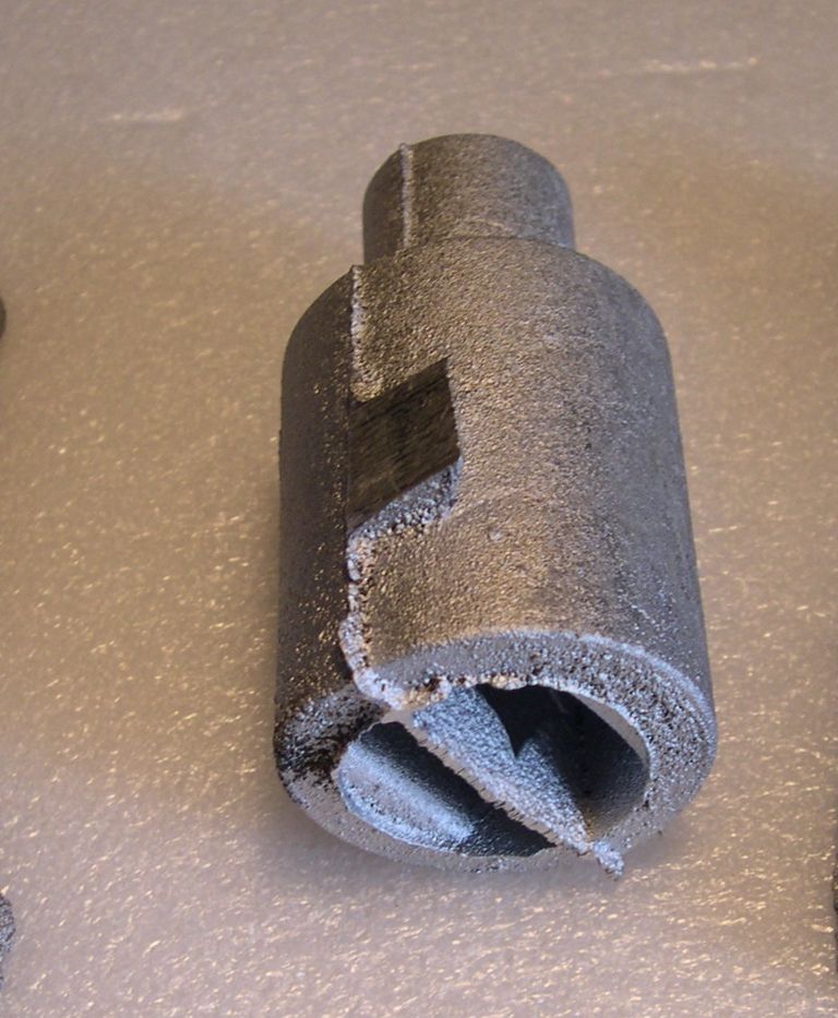
The pistons are cored aluminum castings with a substantial chucking piece attached. (disregard the web through the centre of the cored hole in the picture, it's just casting flash). The first job was to mount in the 4 jaw and set the chucking piece to run as true as possible then turn it to just clean up. On measuring the cored hole to the outside it was found that they were all off centre, not really surprising. The worst one was chosen and chucked in the 4 jaw by the chucking piece and adjusted till the cored hole was centred on the lathe axis as best as could be achieved. The outside was skimmed to clean up (the rough castings were well over size by about .2" ). The bore was then checked with a mike and the chuck adjusted as necessary to re-centre the cored hole and the OD re-skimmed to true it up.
All three were done to this stage with the bores all ending up within a thou or 2 of being centred (the bores will not be machined). They were then chucked in the 3 jaw by the body and the chuck adjusted till the outer surface of the piston was as true as possible. The chucking spigot was then turned to .844 (27/32" ) so it could be held in a 5C collet in a collet block to drill and ream the piston pin hole. Reversed in the chuck and trued up the OD was turned to a close fit in the cylinder bores, about .0005" smaller than the bore.
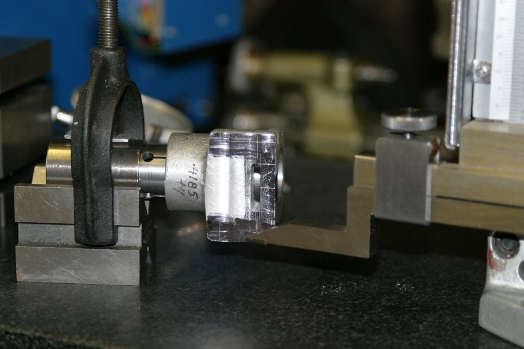
Held by the chucking spigot in a 27/32" 5C collet in a collet block, the hole was drilled in stages to 5/16" then bored to .360" and reamed 3/8" for the piston pin. The piston pins are 3/8" x 1.350 drill rod with a .185" x .038" flat milled on each end and are retained in the piston by two 6-32 setscrews up through the skirt. The pins are shown as solid, but I have made them hollow to help reduce the reciprocating weight.
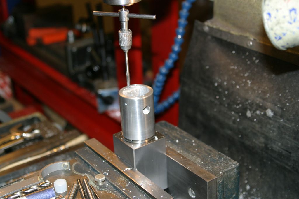
The collet block turned through 90 degrees for drilling and tapping the piston skirt 6-32 for the piston pin retaining setscrews.
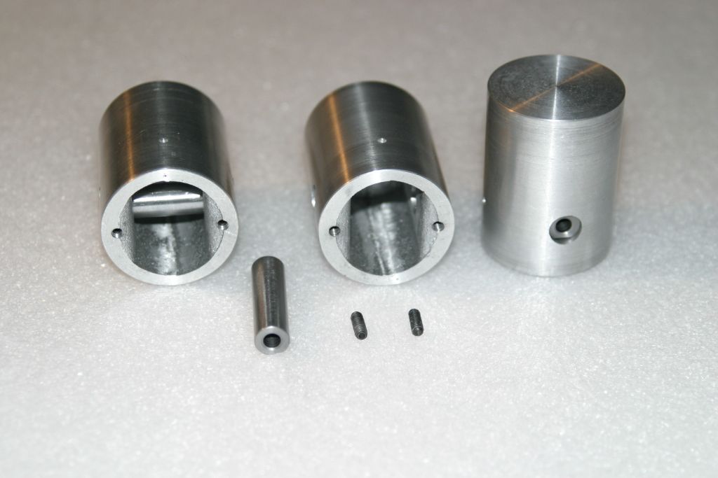
The finished pistons and pins after removing the chucking spigots and cleaning up the top face.
Edited By John Purdy on 04/12/2020 06:29:36
Edited By John Purdy on 04/12/2020 06:30:36
6 December 2020 at 04:05 #511896 garyParticipant@gary44937
coming on nicely john.
8 December 2020 at 22:29 #512485 John PurdyParticipant@johnpurdy78347
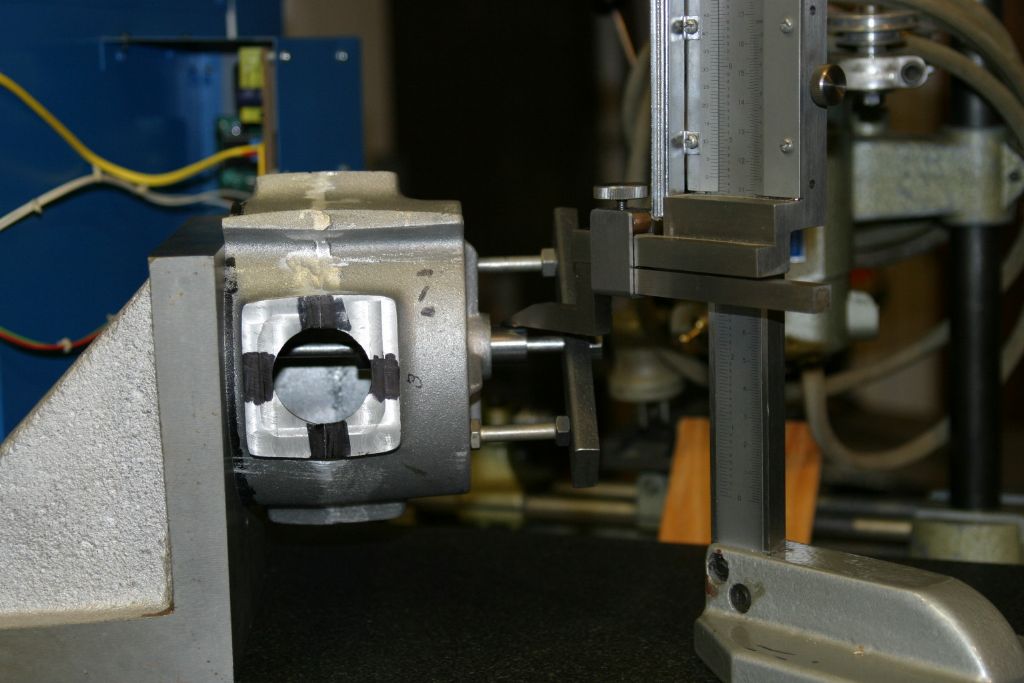
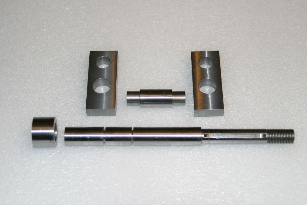
To mark out the crankcase for the cylinder bore centre lines, first the turned rear face was placed on the surface plate and the vertical centres, 1.350" from the rear face, were marked out. But how to mark out the horizontal centres coincident with the crank centre line required a bit of thought. My solution was to turn up a close fitting hollow plug to fit the front crankshaft bearings.
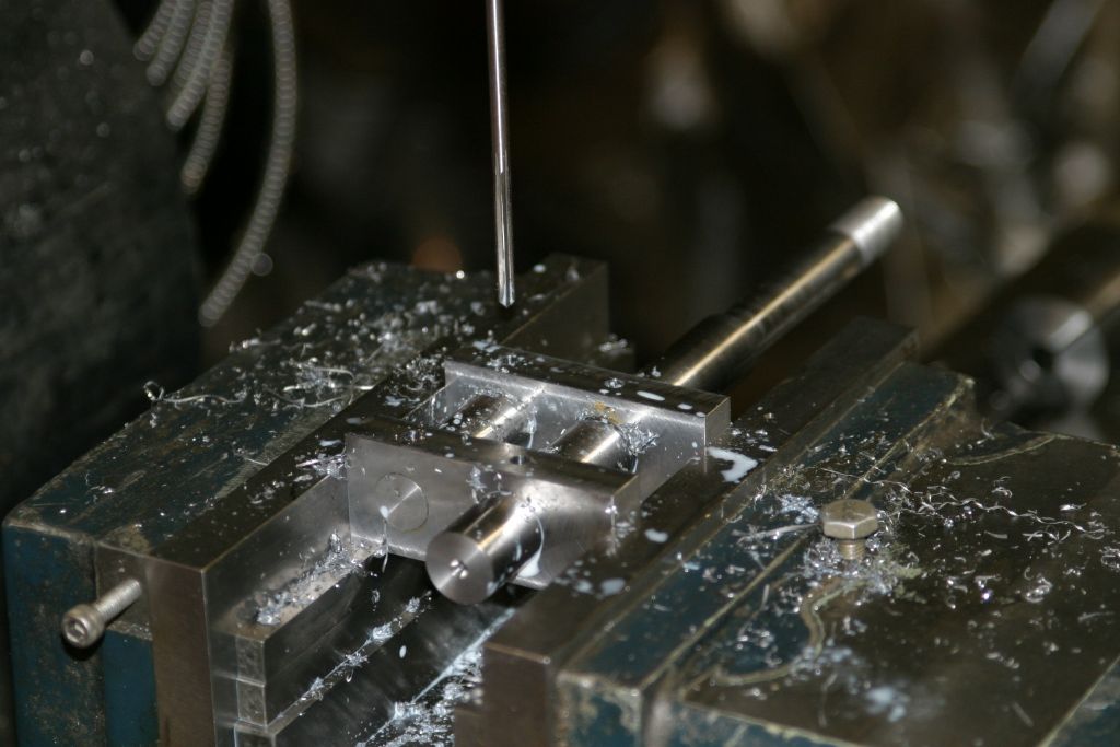
The crankcase was then mounted on an angle plate by a central stud through the hollow plug and the cylinder mounting face set vertical. The OD of the plug was then used as a datum to find the crank centre line to mark out the horizontal cylinder centre line.
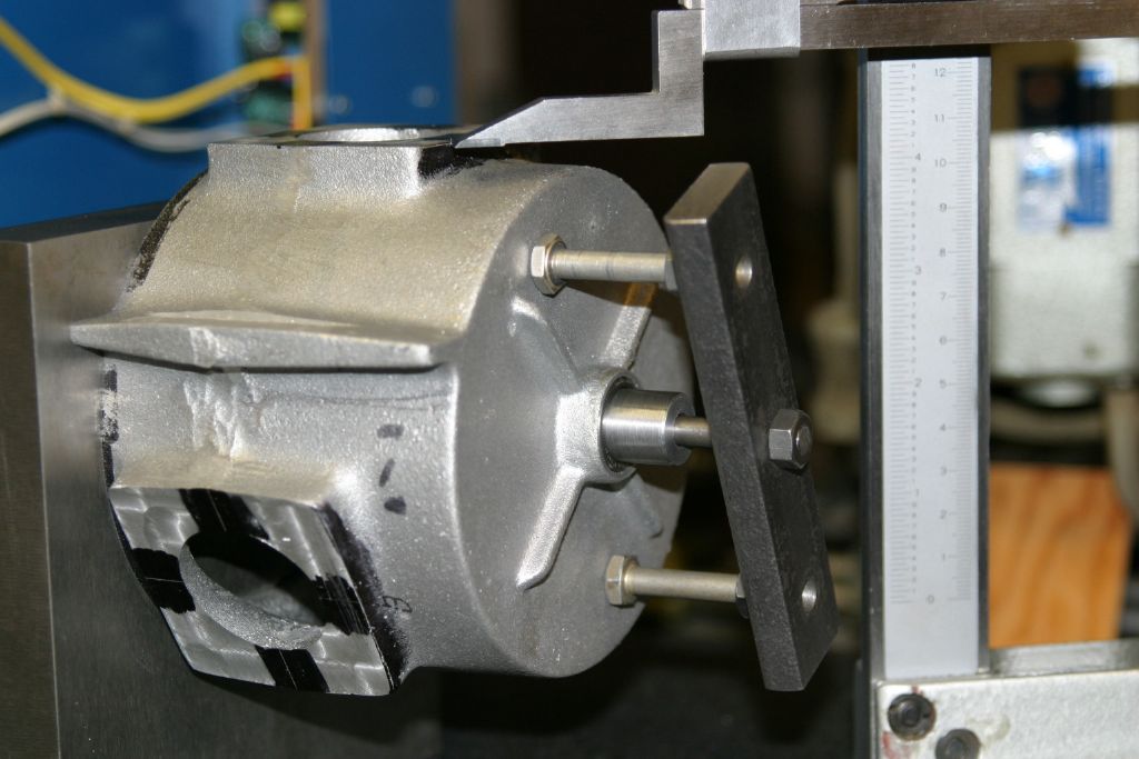
The cylinder mounting face was then turned horizontal to mark it out 2.400" above the crank centre line again using the OD of the plug to determine the crank centre line.
18 December 2020 at 20:46 #514242 John PurdyParticipant@johnpurdy78347
To mark out the crankcase for the cylinder bore centre lines, first the turned rear face was placed on the surface plate and the vertical centres, 1.350" from the rear face, were marked out. But how to mark out the horizontal centres coincident with the crank centre line required a bit of thought. My solution was to turn up a close fitting hollow plug to fit the front crankshaft bearings.
The crankcase was then mounted on an angle plate by a central stud through the hollow plug and the cylinder mounting face set vertical. The OD of the plug was then used as a datum to find the crank centre line to mark out the horizontal cylinder centre line.
The cylinder mounting face was then turned horizontal to mark it out 2.400" above the crank centre line again using the OD of the plug to determine the crank centre line.
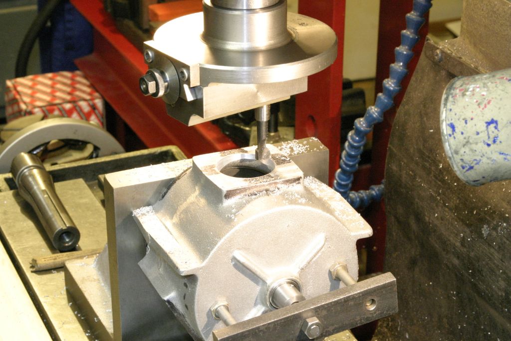
Setup on the mill on the angle plate to bore the holes for the cylinder liner skirts. Once finished the mounting face was milled back to leave it 2.400" from the crank centre line. The holes (tapped 8-32) for the cylinder mountings will have to wait till the long #29 drill I have on order arrives. I could have extended a normal one but I had some other things to order so figured I might as well get one.
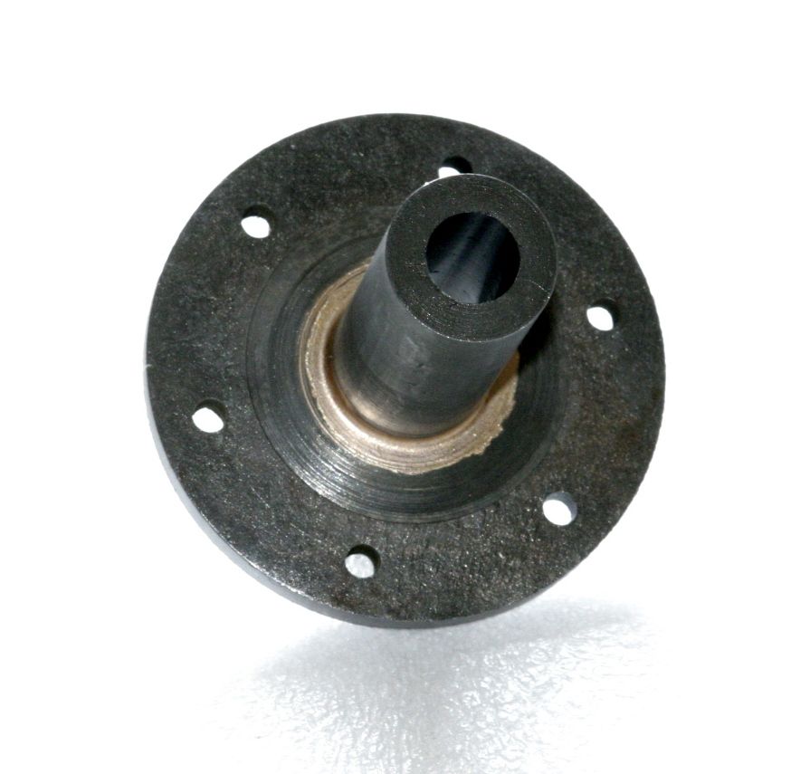
Next I guess will be the crankshaft, I've put it off as long as possible, not one of my favorite jobs. It will be built up and assembled with retaining compound and pins. A couple of weeks ago I milled down a piece of 1/2" x 1 1/2"x 5 1/8" black bar (all I had!) to about 25 thou oversize for the webs (the finished webs are .440" x 1.000" x 2.470" ). The 5/8" dia. crankshaft is reduced to .500" for 3.000" at the front end for the prop hub and threaded 1/2-20 for a retaining nut. The prop hub consists of a central barrel .875" x 2.420" with a 3" dia. x 1/4' thick rear flange attached and a loose 3" dia x 3/16" front pressure plate. It is bored .500" with an 1/8" keyway for attaching to the crank. The drawing gives no indication of how the rear flange and barrel are attached so my plan is to silver solder them together.
The barrel and rear flange were turned oversize and the barrel drilled and bored to .015" under size for reaming after soldering together. A spigot was turned on the barrel a loose fit in the central hole in the rear flange. Rather than get out my large propane torch (its pouring rain outside at the moment!) I'm going to try using my furnace to heat the assembly.
Here's the result. I thoroughly fluxed the assembly and slipped a ring of 1/16" dia Easy-Flo 45 SS over the barrel and down against the rear flange. I set the temperature of the furnace to 640 deg C and when stabilized put the hub in. Ten minutes later it was up to temperature and the SS had melted. Once cooled and pickled there was a good penetration of SS all around the spigot out to the back of the flange. It was then set up in the lathe and the rear of the flange and OD skimmed true and the bore reamed to .500" dia. The front face of the flange and the OD of the barrel will be finished to dimension mounted on the crank, ensuring it runs true. I will use the hub to dimension the turned down front of the crank as I find it easier to turn an OD to fit an ID rather than the other way around. Besides the reamer may well have cut oversize.
The bore of the hub has an 1/8" keyway cut in it for the drive from the crank. I have an 1/8" "B" broach but the max length of cut is listed as 1 11/16" and the hub is 2.4" long. I suspect that this max is governed by the gullets filling up with chips. I don't want to risk the broach jamming so I think I will plane out most of the material in the lathe first. I have done keyways that way before and it works, although is tedious and slow.
Edited By John Purdy on 18/12/2020 20:53:41
19 December 2020 at 15:49 #514369Howard Lewis
Participant@howardlewis46836Progressing well!
Will be an exciting moment when finally assembled and then run!
Howard
26 December 2020 at 04:14 #515454 John PurdyParticipant@johnpurdy78347
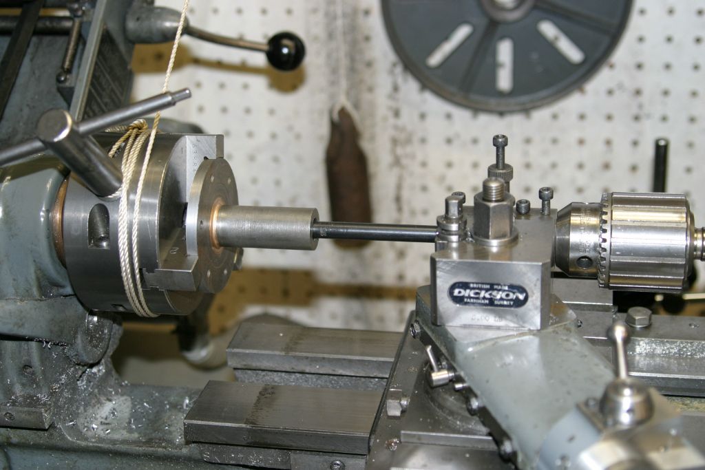
Set up in the lathe for the initial planing out of the keyway with a boring bar. The back gear was engaged without releasing the bull wheel to hold the chuck in position. Before anyone comments on the chuck key left in the chuck, its holding the end of the cord wound around the chuck connected to a weight (seen hanging on the back wall) to take up the backlash in the gears. The primary drive belt was removed as a safety to prevent the chuck rotating accidentally. I fed in for a total of .020", using the tail stock to push the carriage and the tool through the bore. This left about .012" for the broach to take out on the first pass. This size of broach cuts a keyway in two passes of .032" each, the first in the bushing alone and the second with a 1/32" shim placed in the back of the slot in the bushing to advance the broach for the second finishing cut.
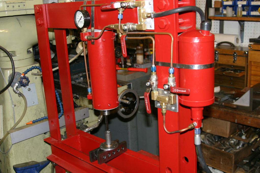
The hyd. press was then used to finish the keyway with the broach. Since the hub is considerably longer than the broach bushing a second bushing was inserted in the bore from the bottom to support the broach for the full length of the bore. The broaching was done in three passes, the first in the bushings themselves, half of the material already having been taken out in the lathe, the second with a .015" shim in the back of the bushings and the third with a .032" shim in the bushings. The two shims were home made and long enough so the broach was supported for the whole length of the hub. The final result was a good keyway the length of the hub. The worst part was since the broach,hub and support parallels were of quite a height I had to reposition the bed of the press twice for each pass. Took longer to do that than the actual broaching.
1 January 2021 at 01:04 #516605 John PurdyParticipant@johnpurdy78347
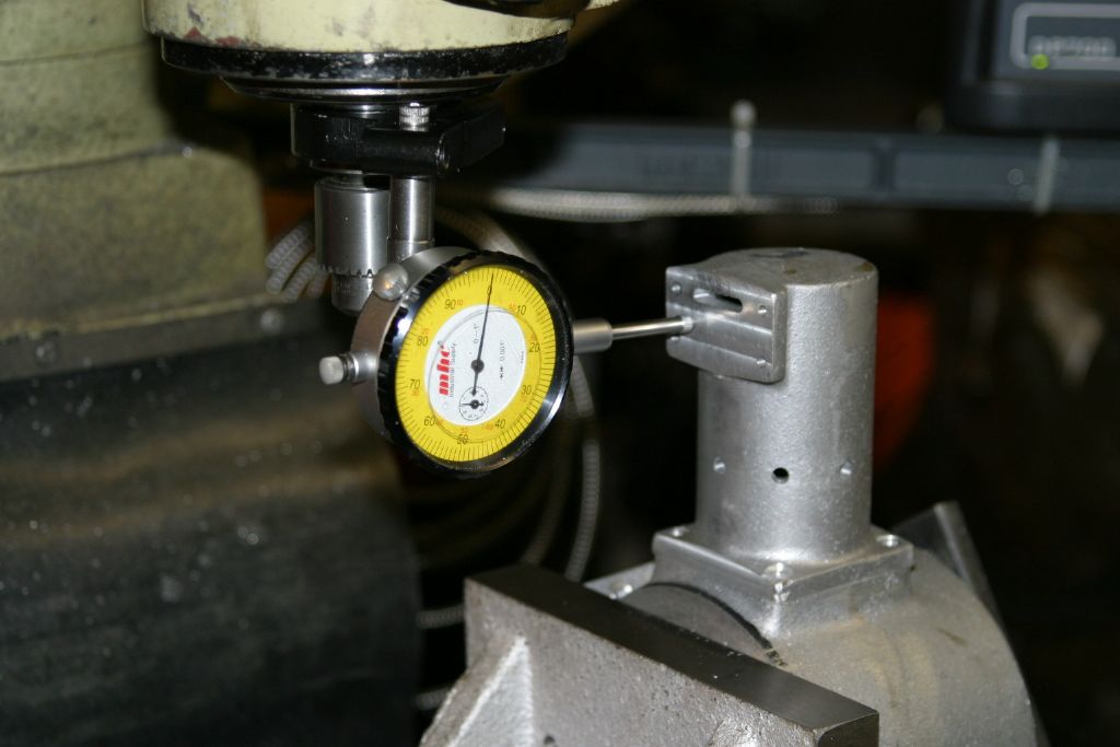
Back to the crankcase set up on the angle plate to drill and tap the holes for the cylinder mounting screws. First job was to align the valve body mounting face parallel to the crankcase rear face.
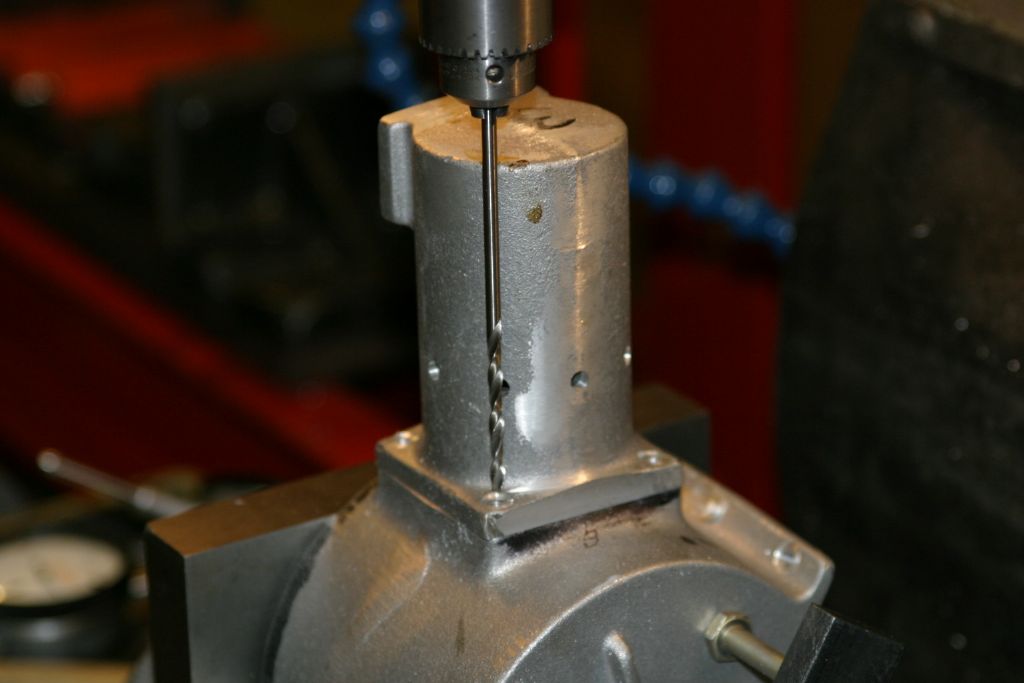
Using a long series #29 drill to spot through and drill the cylinder mounting holes. The two front ones could be done this way but for the rear ones the flange on the valve body mounting face is in the way so they will have to be spotted through with a short transfer punch before drilling and tapping.
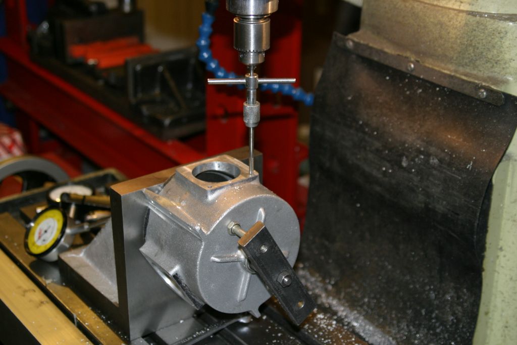
Tapping the holes 8-32 for the cylinder mounting screws.
1 January 2021 at 06:55 #516619 John PurdyParticipant@johnpurdy78347
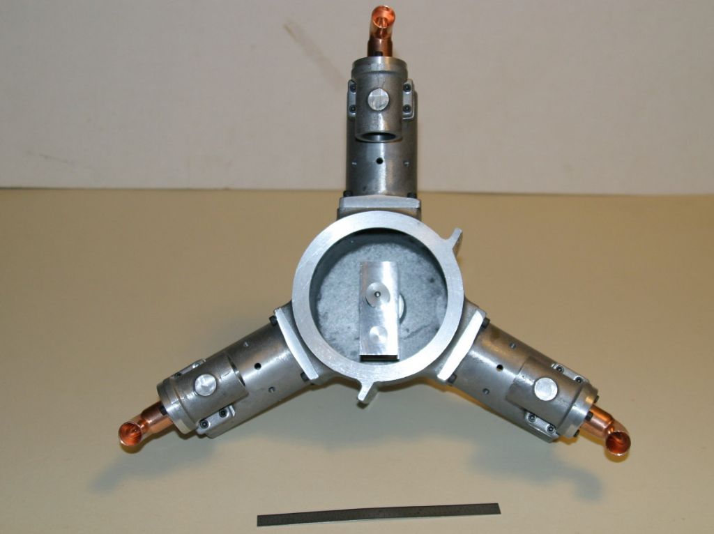
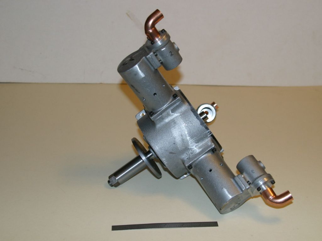
Here are a couple of pictures of the parts assembled so far with the part finished crankshaft but not including the pistons. Once the crank is finished the rear crankcase cover can be finished as it contains the rear crankshaft bearing and sets the crankshaft end float. Note the 6" rule at the bottom to give a sense of scale.
1 January 2021 at 07:30 #516624 Michael GilliganParticipant@michaelgilligan61133
Fascinating project, John
… looking good !
MichaelG.
1 January 2021 at 09:17 #516632Howard Lewis
Participant@howardlewis46836Excellent work, and good progress!
Howard
9 January 2021 at 06:38 #518561 John PurdyParticipant@johnpurdy78347
The aluminum casting for the rear crankcase cover was held in the 3 jaw reverse jaws to skim the central boss to true it up so it could be reversed in the chuck and the OD skimmed to true it up. The rear crank bearing is a bushing 1.125" OD x .950" ID with .125" thick flange 1.25" dia. to act as the rear thrust bearing for the crank. The central boss which supports this bushing is supposed to be 1.25" dia., the same as the flange on the bushing, but as cast was just over 1" so after skimming to clean up a ring was turned up and fastened on with high strength retaining compound to bring it up to 1.25". Held in the reverse jaws by the OD the central boss was bored for a press fit for the rear crank bushing. After pressing in the bushing the cover was held in the reverse jaws, boss outermost, and spaced out sufficiently from the jaws so that a .045" deep rebate could be turned on the inner face at the OD to act as a register in the rear bore of the crankcase. The ID of the bushing was then bored to size (it had been made under size) to fit the rear of the crankshaft. At the same time the face of the flange was skimmed to true it up and the rebate at the OD was machined to be a good fit in the crankcase, ensuring that the crank bearings would line up. The distance between the face of the rebate and the face of the bushing was adjusted so that when assembled with the crank, there was 1-2 thou end float to the crank. On the drawings, at one place the dimension given for this distance gives zero end float, but at another place on the same drawing it shows 2 thou end float.
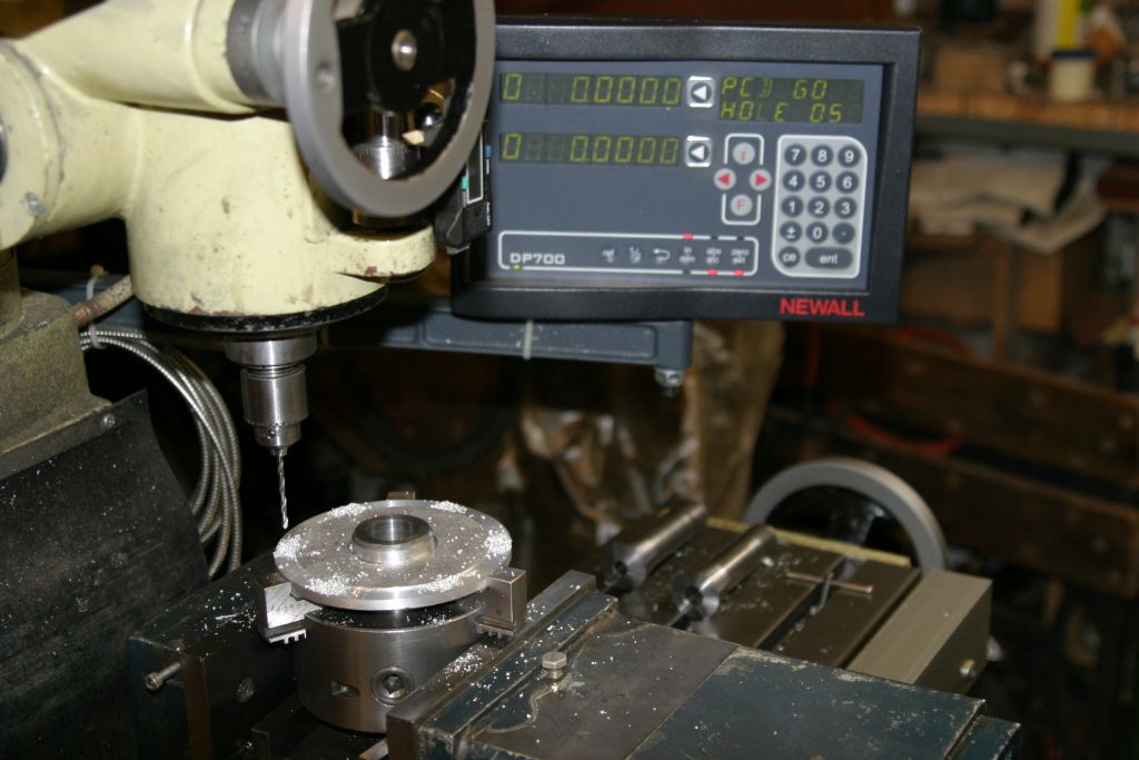
After ensuring that the crank rotated freely in the front and rear bearings and the end float was good the cover was transferred to the mill, still in the chuck, and the DRO PCD function was used to drill the six #36 tapping holes for the 6-32 screws that fasten it to the front crankcase. The holes were then transferred to the front crankcase and tapped for the screws.
Edited By John Purdy on 09/01/2021 06:43:53
9 January 2021 at 07:49 #518563 John PurdyParticipant@johnpurdy78347
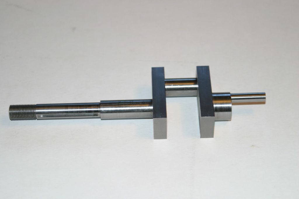
Boring out the webs for the crank pins (.503) and the crankshaft (.628). The ends of the .625" crank pin will be turned down to .500". The holes were bored .003 over size to allow clearance for the retaining compound which according to the specs is in the middle of the recommended clearance for maximum strength.
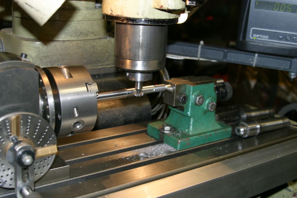
Cutting the key way .070" deep in the crank for the prop hub drive key with a #504 woodruff key seat cutter, having taken great pains to ensure that the shaft was parallel to the mill table in both the vert. and horiz. planes. It paid off as the hub slid on over the key with no problems and no shake.
The parts of the crankshaft ready to be fastened together with high strength retaining compound. There is still the large counterweights to be made, but at the moment I don't have any suitable material. They are 1.200" deep sectors of a 3.520" diameter circle, one being .850" thick and the other .700" thick, each fastened to the webs with two 10-32 hex socket cap screws.
After fastening the parts together and given 24 hours to cure, the crank was set up in the mill to drill and ream for the 5/32" cross pins.
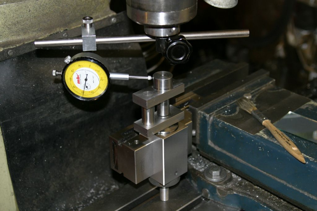
The setup I used to drill and tap the 1/4-28 hole in the rear end of the crankshaft for the valve eccentric drive pin. I would have preferred to use the dividing head set vertically and the 3 jaw but there was insufficient head room on my mill. As it was with this setup there still was no head room to use my co-axial centre finder (a great piece of kit but it takes up about 6" of head room), hence the use of the dial gauge in the picture to centre it under the spindle. The mill PCD function on the DRO was used to position the hole for the eccentric pin at a radius of .275" and 60 degrees CCW from the crank pin.
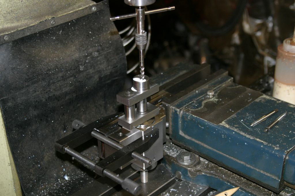
Tapping the end of the crank for the eccentric pin after drilling #3 x 5/8" deep. The clamp across the collet and vice was put on as I thought that the offset drilling pressure might possibly move the collet block in the vice.
The completed crankshaft except for the two counter weights. The outer end of the eccentric pin still needs to be finished. The plans call for it to be threaded 1/4-28 for a nut and washer but I think I will tap it and retain the washer with a small hex socket cap screw. The length will have to wait till the eccentric (for lack of a better name) is made so as to set the end clearance.
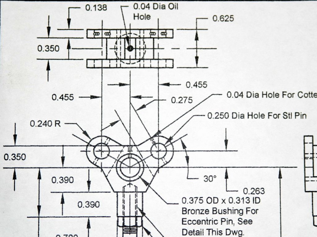
The "eccentric" is a "Y" shaped unit, as seen here, with the three valve rods attached, one fixed and the other two pivoted and is driven by the pin on the end of the crankshaft. I can see two possible ways of making it. One, out of the solid involving a lot of hack sawing and or milling, the other built up from a central piece and two thinner outer cheeks, still involving hack sawing and milling but maybe less so. Haven't decided which way to go yet.
9 January 2021 at 08:01 #518565 JasonBModerator@jasonb
Your making good progress.
With manual machines I think I would tackle the eccentric by starting with a block that it can be got out and add the three main holes on the mill. Then hold in 4-jaw to turn the spigot and tap the hole. After turning teh spigot there won't be masses to come of so could all be milled if you don't fancy sawing.
Get the rotary table out set up vertically and mount by central hole to do most of the external shape and the two .350" wide slots, pin hole sand oil hole can be done at this time. Then filing buttons or mounted on an arbor to round the ends over.
-
AuthorPosts
- Please log in to reply to this topic. Registering is free and easy using the links on the menu at the top of this page.
Latest Replies
Home › Forums › Stationary engines › Topics
-
- Topic
- Voices
- Posts
- Last Post
-
-
First lathe – warco 180/210
Started by:
Chris12 in: Beginners questions
- 4
- 5
-
4 June 2025 at 08:22
Chris12
-
Stuart? MTB 1M
Started by:
 JasonB
in: Stationary engines
- 3
- 5
-
4 June 2025 at 08:22
 David George 1
-
They don’t make them like they used to.
Started by:
David Ambrose in: The Tea Room
- 5
- 5
-
4 June 2025 at 08:03
Chris Crew
-
Clayton Steam Wagon
Started by:
Paul Lousick in: Traction engines
- 8
- 19
-
4 June 2025 at 07:41
Werner Schleidt
-
Searching for leak proof quarter turn water shut off valves
Started by:
Greensands in: Hints And Tips for model engineers
- 4
- 6
-
4 June 2025 at 07:04
Alan Charleston
-
Model dynamo drawings
Started by:
Dougie Swan in: General Questions
- 5
- 10
-
4 June 2025 at 06:52
 JasonB
-
Gib adjustment on SX2 P mill
Started by:
John Gray 7 in: Workshop Techniques
- 3
- 6
-
4 June 2025 at 06:34
 Michael Gilligan
-
Boiler Design – issue 4765
1
2
…
4
5
Started by:
Charles Lamont in: Model Engineer & Workshop
- 22
- 119
-
4 June 2025 at 06:15
 Michael Gilligan
-
ElectroMagnetic Pendulum thing
Started by:
 Michael Gilligan
in: Clocks and Scientific Instruments
- 1
- 1
-
4 June 2025 at 06:04
 Michael Gilligan
-
Dodgy drawings
Started by:
DMB in: Drawing Errors and Corrections
- 3
- 3
-
4 June 2025 at 01:20
Paul Lousick
-
Keratin Glue
Started by:
 Michael Gilligan
in: Materials
- 16
- 19
-
3 June 2025 at 22:59
Nigel Graham 2
-
1950 Myford/Drummond type m advice
Started by:
jimmyjaffa in: Beginners questions
- 4
- 9
-
3 June 2025 at 22:33
 David George 1
-
Suds tray sealant
Started by:
Dave S in: General Questions
- 3
- 3
-
3 June 2025 at 22:05
ChrisLH
-
Stuart 10V Cast Iron problem
Started by:
barry in: Help and Assistance! (Offered or Wanted)
- 2
- 2
-
3 June 2025 at 20:39
 JasonB
-
Sieg Mini Mill Problem
Started by:
Andy Brocklehurst in: General Questions
- 4
- 7
-
3 June 2025 at 18:55
 JasonB
-
Drunk driver broke my workshop!
1
2
Started by:
 stew 1
in: The Tea Room
- 19
- 41
-
3 June 2025 at 18:23
DMB
-
Newbie from Birmingham
Started by:
jimmyjaffa in: Introduce Yourself – New members start here!
- 6
- 7
-
3 June 2025 at 17:58
 Harry Wilkes
-
New Control Box for Denford Triac
Started by:
Richard Evans 2 in: CNC machines, Home builds, Conversions, ELS, automation, software, etc tools
- 7
- 17
-
3 June 2025 at 17:56
Richard Evans 2
-
A new lathe
Started by:
 Sonic Escape
in: The Tea Room
- 7
- 9
-
3 June 2025 at 16:59
 Sonic Escape
-
Replacement gear
Started by:
 David George 1
in: Manual machine tools
- 9
- 12
-
3 June 2025 at 16:33
old mart
-
Is content in ME&W being written by AI?
Started by:
norm norton in: Model Engineer & Workshop
- 8
- 9
-
3 June 2025 at 15:08
parovoz
-
A parallell action hand vice
Started by:
 Fulmen
in: Workshop Tools and Tooling
- 10
- 22
-
3 June 2025 at 13:03
Clive Foster
-
Cooked motor
Started by:
 jimmy b
in: Manual machine tools
- 5
- 11
-
3 June 2025 at 12:01
 jimmy b
-
Taylor Hobson Type CX or Type D?
Started by:
colinb in: Manual machine tools
- 4
- 8
-
3 June 2025 at 07:48
 Michael Gilligan
-
Pallet delivery recommendation
Started by:
Richard Evans 2 in: General Questions
- 7
- 8
-
2 June 2025 at 19:35
Ian McVickers
-
First lathe – warco 180/210
-
Latest Issue
Newsletter Sign-up
Latest Replies


