Thomson-Houston Co Motor Wiring

Advert

Thomson-Houston Co Motor Wiring

Home Forums Workshop Tools and Tooling Thomson-Houston Co Motor Wiring

Viewing 15 posts - 1 through 15 (of 15 total)
  • Author
    Posts
  • #402991
    Jamie Wood
    Participant
      @jamiewood67138

      motor2.jpg

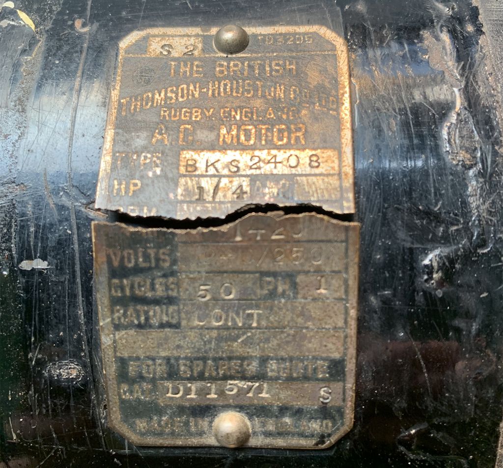
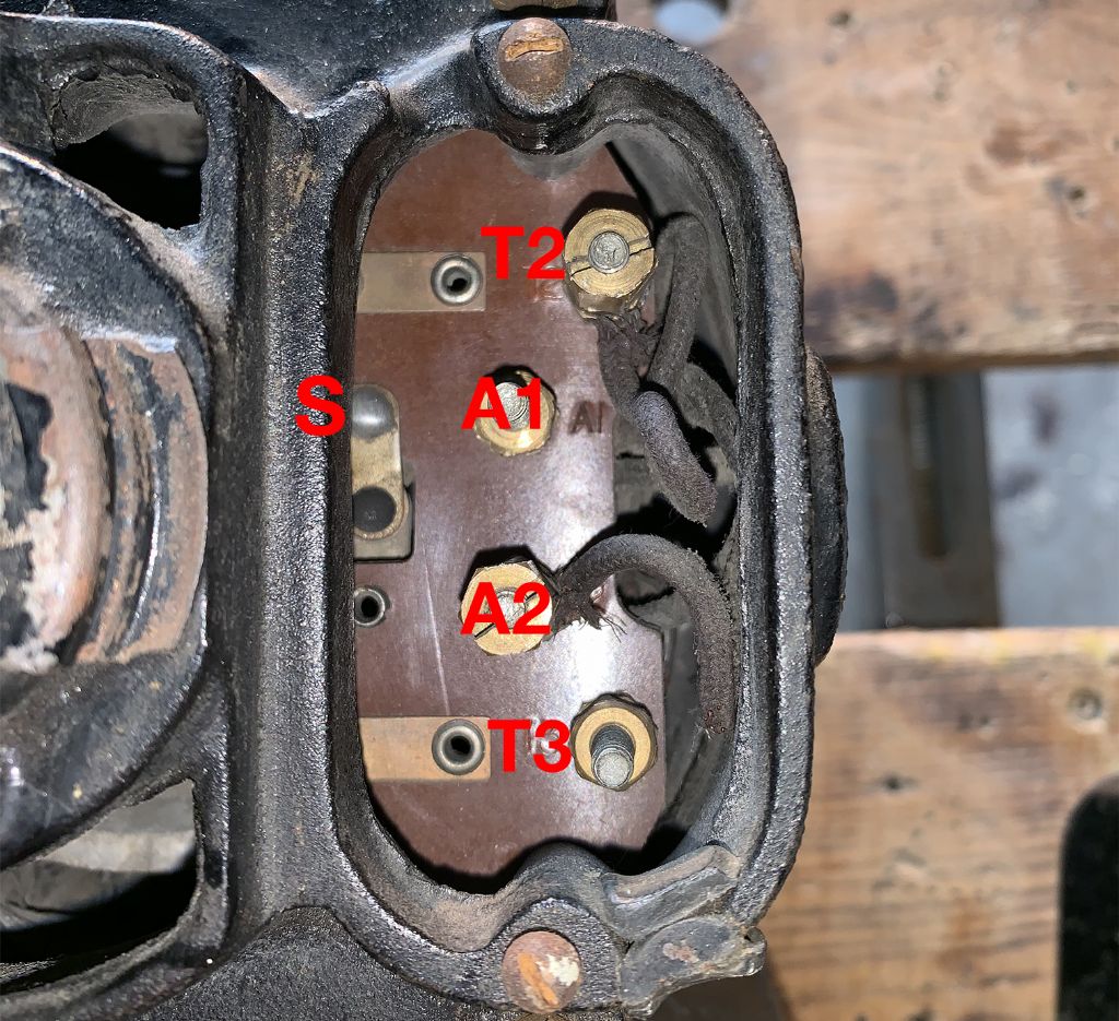
      So I recently picked up a 1/4hp Thomson Houston Motor in a job-lot of tools, I already have a 1/3hp one wired up in my drill press and I'd like to turn this one into a disc sander. Problem is this one is wired up differently to the running one I have already. The working one is wired to A1 and A2. Neither have capacitors so I assume they are induction motors. Neither had any instructions on the case for wiring. I wasn't sure whether this had been wired differently to work with some sort of reversing switch?

      There was another thread on here with an almost identical AEI motor that also came to the conclusion that A1 and A2 were the correct wiring for motors with no capacitors.

      motor1.jpg

      This one has internal wires going to A2 and T2. When wired to these two I get a humming sound and no spinning so I tried moving wire T2 to A1. This got the motor running but there was a small spark at S. I stopped and tried measuring continutity/resistance to see if I could work out the different windings but the only thing I'm totally sure about is that T3 isn't connected to anything.

      A2 > T2 9 Ohms

      A2 > A1 22.2

      A1 > T2 31

      Has anyone else had one of these motors or similar and can point me in the right direction? Or does the spark mean it likely has a fault and there was a reason this wasn't wired to a plug already.

      Thanks,

      Jamie

      Edited By Jamie Wood on 31/03/2019 20:54:36

      Advert
      #19292
      Jamie Wood
      Participant
        @jamiewood67138
        #402998
        Anonymous

          Hmmm, single phase low power AC motor with no capacitors? Could well be a shaded pole motor. Been there, done that, and binned the motor. When I first got my surface grinder it had been modified to have separate motors for spindle and power feeds. The spindle motor disappeared in a shower of sparks in short order; that's rubber insulation for you. So I decided to revert to the original design of a single motor in the base driving both spindle and feeds. For that I needed to reverse the motor in the base. I tried all combinations, for one configuration it ran, but all the others it grunted or made buzzing noises with no action. Talking about it at work someone suggested it was a shaded pole motor, which generally can't be reversed unless you take them apart and physically reverse the shaded pole. Shaded pole motors aren't really suited to machine tools as they have almost no starting torque. In the end I binned the motor and fitted a 3-phase one.

          The T terminals may be some sort of temperature device, although shaded pole motors are noted for only a small increase in current drawn in the event of a stalled rotor.

          Andrew

          #403002
          john fletcher 1
          Participant
            @johnfletcher1

            In your own interest and well being and before doing any thing at all, you ought to carry out an insulation test on the motor windings, using 500 volt DC Insulation tester, this test will tell if the motor is safe to use. The motor is obviously very old. Having got that off my chest and using your values of resistance A2 & T2 is your run winding and A2 & A1 the start winding. These two windings should be connected in parallel one to another. Supply to A2 & T2 and your motor should run in one direction or other and don't forget that good sound and clean earth connection.The sparking came from the internal centrifugal switch which is connected in series with A1 & A2. John

            #403003
            Jamie Wood
            Participant
              @jamiewood67138

              Thanks Andrew,

              The other working one I have I reversed successfully by swapping the wires to A1/A2 terminals. I was thinking from what I'd read that this was maybe a split phase motor?

              Thanks John, just read your comments re. sparking

              Jamie

              Edited By Jamie Wood on 31/03/2019 21:56:25

              Edited By Jamie Wood on 31/03/2019 21:56:39

              #511243
              Ric Goodman
              Participant
                @ricgoodman21893

                I now have my own 0.5hp 240v 1ph BHT motor on a Kerry's Super 8 drill press and evaluating whether it is safe to continue to run it or better to replace it. The motor runs quietly so assume bearings are fine. Apart from blowing a great cloud of black dust out of it with an airline I have not investigated further at this stage.

                I found a slip of paper inside the terminal box and have scanned it and added to my photo album for reference. Terminals A1 and A2 are for live and neutral, presumably either way round. Says "To reverse rotation interchange leads from inside motor to terminals" which leaves me none the wiser.

                For those who've not found it, there is a helpful thread on the same topic here: https://bbs.homeshopmachinist.net/forum/third-hand/58857-split-phase-motor-reversal-opening-motor-casing

                Two questions I have:

                1/ Could someone please recommend a suitable switch (or spec for a switch to help my search) – should I replace the knackered press switch (with its asbestos insulation) with a NVR or is a simple on/off sufficient for this kind of motor.

                2/ How is this supposed to be earthed? There is no earth cable or indication for an earth cable from the motor to the switch. Concerned about a 10A supply attached to 110 kg of cast iron with a human providing the conductor route.

                As you can tell I am completely unqualified to be doing this but can follow clear instructions, so any advice appreciated.

                #511255
                Jamie Wood
                Participant
                  @jamiewood67138

                  Hi Ric,

                  As John mentioned in a message above, I would definitely recommend getting hold of a Megger or similar insulation tester to test your motor. The motor I started this thread about turned out to be pretty iffy when tested, suggesting the insulation was failing despite the motor still running ok. Hence I decided it was safer to use another motor that passed the test.

                  I do have another older motor on my drill press and the motor is earthed with a crimped terminal connector bolted to the bare metal motor frame and then checked with a meter. Does your motor have any extra bolt holes near the wiring box? I wouldn't even plug it in without a solid earth connection.

                  I'm not sure about the switch question though. Hopefully someone else can help with that.

                  Jamie

                  #511295
                  Ex contributor
                  Participant
                    @mgnbuk

                    2/ How is this supposed to be earthed?

                    Top left hand corner of the raised surround near the cover plate screw is a groove. The earth wire is taken through the groove & secured under the cover plate screw using a crimped on eylet of suitable dimensions.

                    In keeping with the age of that motor, there used to be available stamped brass " eylets " that were like a shallow ring with the outer edge being raised fingers – the stripped, twisted wire was formed into a loop, inserted in the ring & the fingers closed with snipe nose pliers to form a hardened " eylet " that could be trapped under the cover screw.

                    If an insulation check comes up a bit low, try putting it in a warm dry place for a few days & trying again. If it has been stored in a damp place, that can affect the insulation reading. I would test it before applying power.

                    Nigel B.

                    #511307
                    Mike Poole
                    Participant
                      @mikepoole82104

                      If you are lucky enough to still have the terminal box cover plate it may have the wiring details cast into it.

                      Mike

                      #511401
                      J Hancock
                      Participant
                        @jhancock95746

                        I am looking at the BTH fractional hp motor diagrams,

                        There are many variations for the BS24 motors, all have A1,A2,T2,T3 on the terminal plate !

                        IF yours has a built-in centrifugal switch then A1, A2 are all you need. T2,T3 are unconnected spares.

                        T2,T3 are used with a capacitor to get a reverse mode.

                        #511402
                        J Hancock
                        Participant
                          @jhancock95746

                          For BS please read BC.

                          Curiously, BK is listed as 3-phase.

                          #511439
                          Ric Goodman
                          Participant
                            @ricgoodman21893

                            Many thanks for replies so far – much appreciated. I forgot to say it is a BS2410 model. I'll work out how to borrow a Megger tester, and attach an earth cable via an eyelet to the screw on the cover plate.

                            I've added some further photos in the album on this. Above the rear bearing there is a vacant screw thread – I assume this is for a wicked ball oiler. Could someone confirm please?

                            Now I understand this can be run in reverse, could anyone provide the exact wiring diagram (i.e. to connect to T2 and TA as J Hancock suggests) and the specs for the capacitor and the type of switch I would need, please?

                            #511528
                            J Hancock
                            Participant
                              @jhancock95746

                              My pocket book shows the BK2408 with foot, axial and radial mounting features.

                              It says BK24 are 3-phase .

                              BS are classed as split-phase, BC capacitor start.

                              Some are shown with hand reset, or auto-reset units mounted on the terminal cover.

                              No mention of S anywhere.

                              The standard connection shows Main winding across A1-A2.

                              Aux (start winding ) in series with centrifugal switch also across A1-A2.

                              Whether you need a capacitor ,or not, for reversing will depend on it being a split phase motor ?

                              #541297
                              MICHAEL HEXT
                              Participant
                                @michaelhext34368

                                I came across this forum while seeking the answer to "How do i get my Thompson-Houston AC motor to reverse it's rotation, my motor type is BKS2410 1/3 hp, Ph !, Rpm 1425.

                                From all your replies I pieced together the answer for mine.

                                Remove the lines in from A1 & A2.

                                Swap around the two wires underneath that connect A1 & A2 to the motor insides.

                                Replace the lines in as before.

                                It worked for mine.

                                Cheers.

                                #553369
                                PAUL MCGUINNESS
                                Participant
                                  @paulmcguinness29893

                                  Hi All,

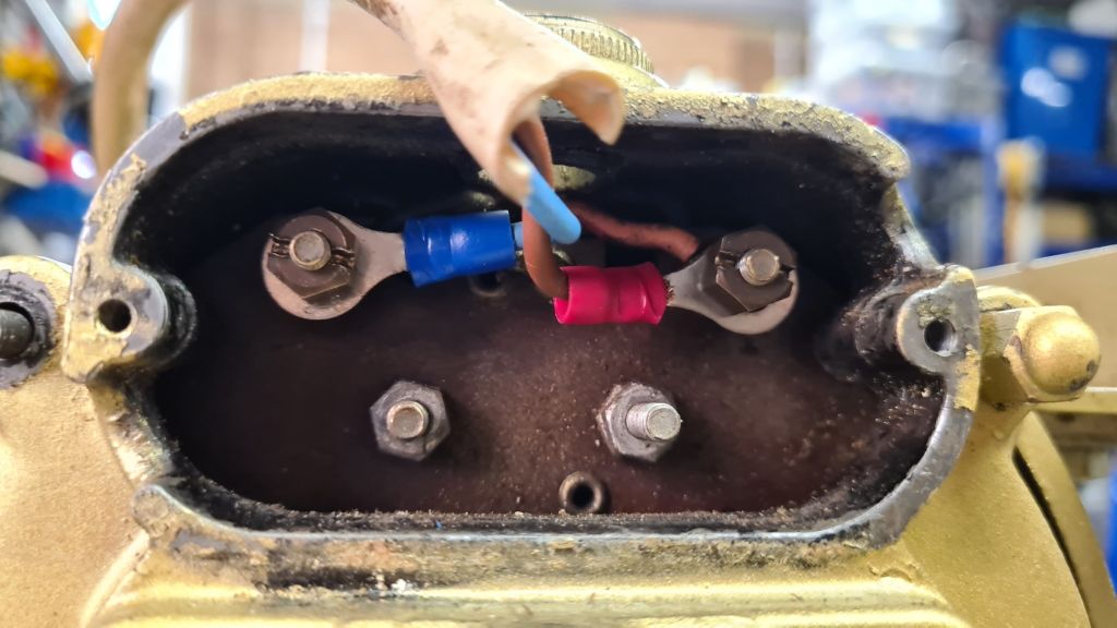
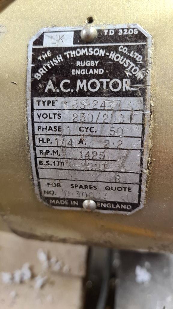
                                  I have a working motor that won't start up without giving the pully a shove… Can someone tell me which connections to put a capacitor on to make it work. I've tried (I think) all of them, but after reading this I am thinking I am either missing something or need to re-wire the back of the connectors.

                                  Cheers,

                                  Paul

                                  20210709_095631.jpg

                                  20210709_095624.jpg

                                Viewing 15 posts - 1 through 15 (of 15 total)
                                • Please log in to reply to this topic. Registering is free and easy using the links on the menu at the top of this page.

                                Advert

                                Latest Replies

                                Viewing 25 topics - 1 through 25 (of 25 total)
                                Viewing 25 topics - 1 through 25 (of 25 total)

                                View full reply list.

                                Advert

                                Newsletter Sign-up