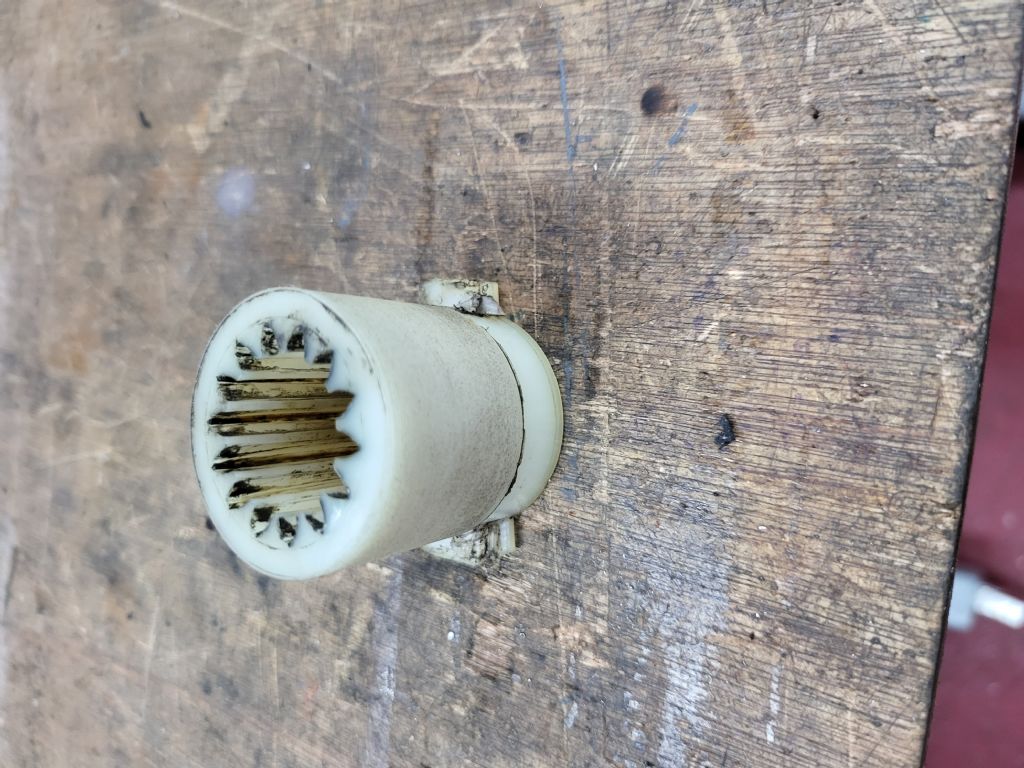
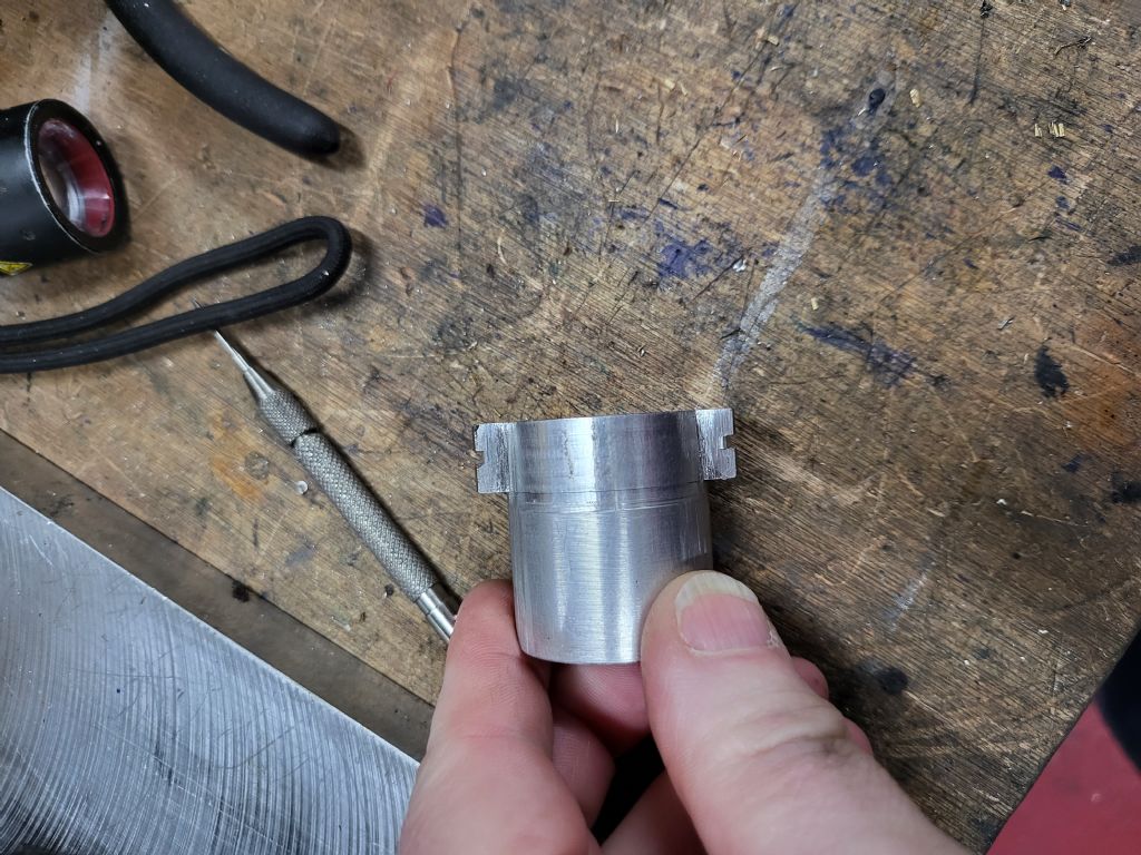
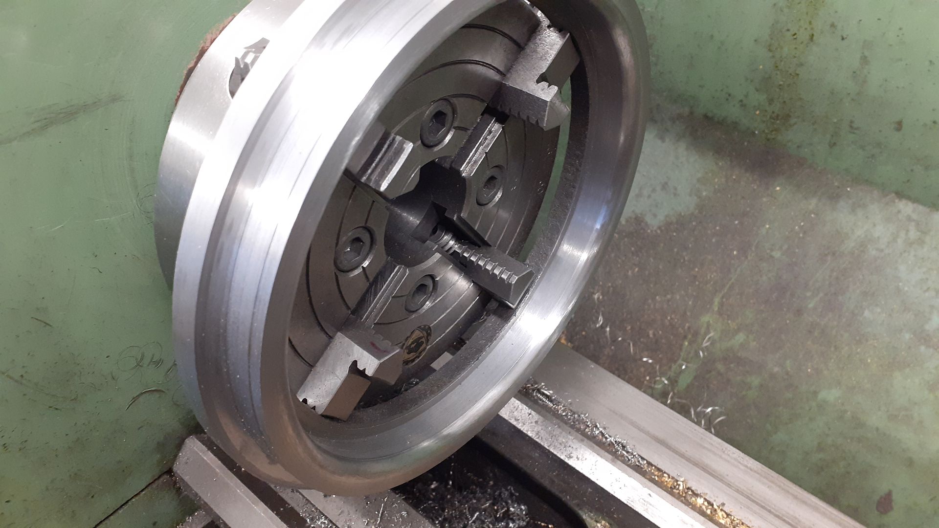
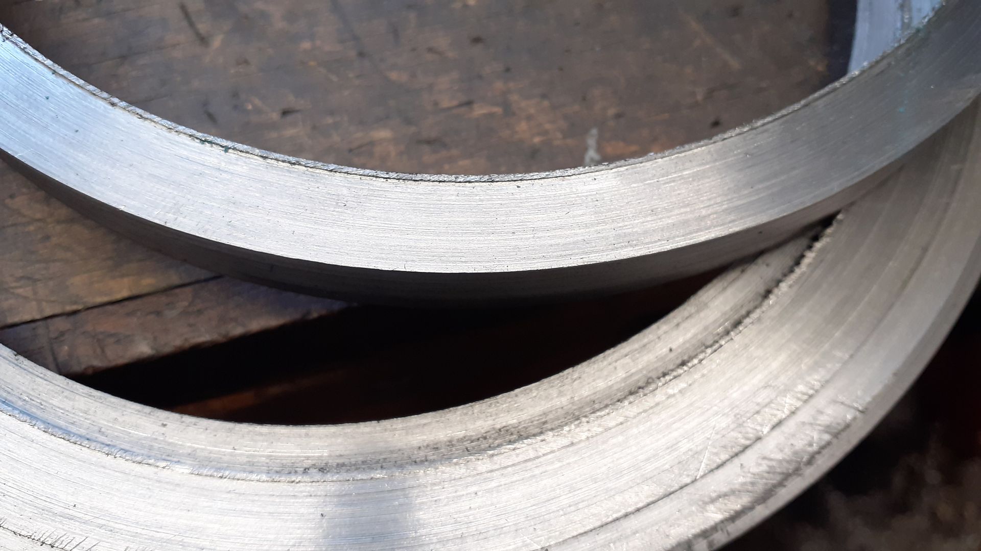
So I lost the spindle drive on my Omnimill. Stripped the pulley section off to find a worn out drive dog that doesnt exist on the parts list I have.
The drivre dog lives in the inside of the top pulley assembly.
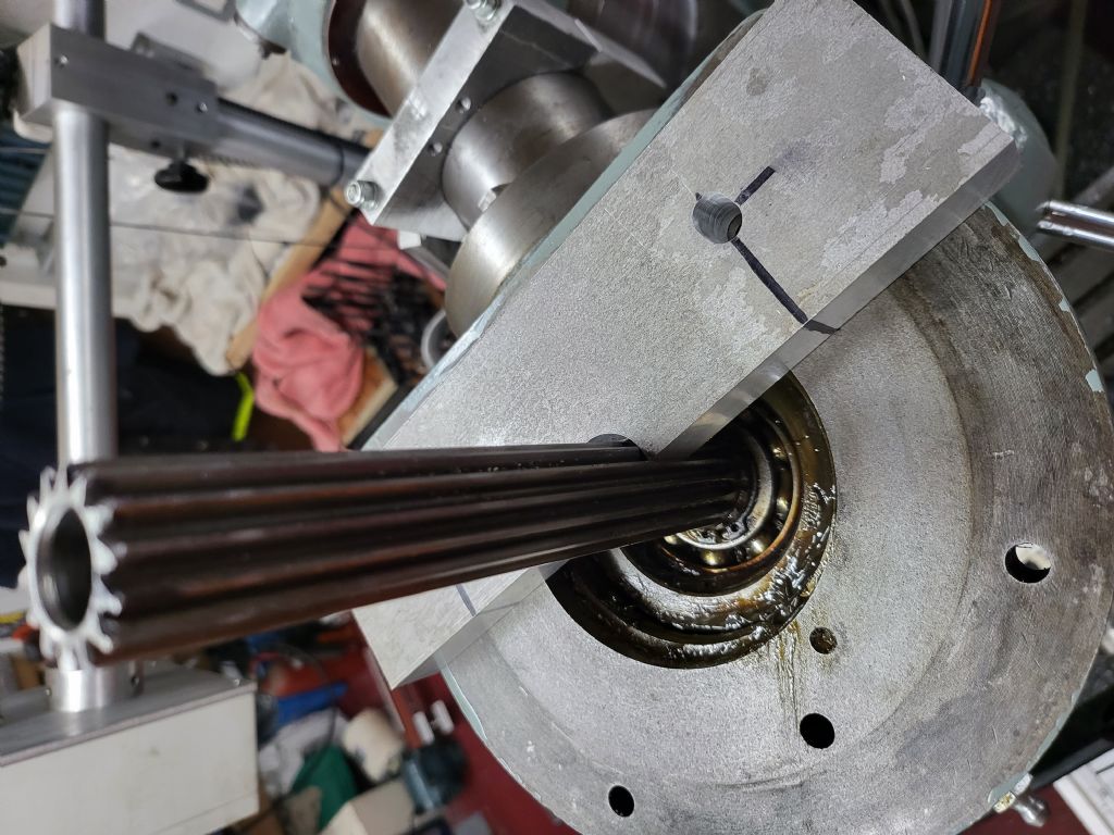
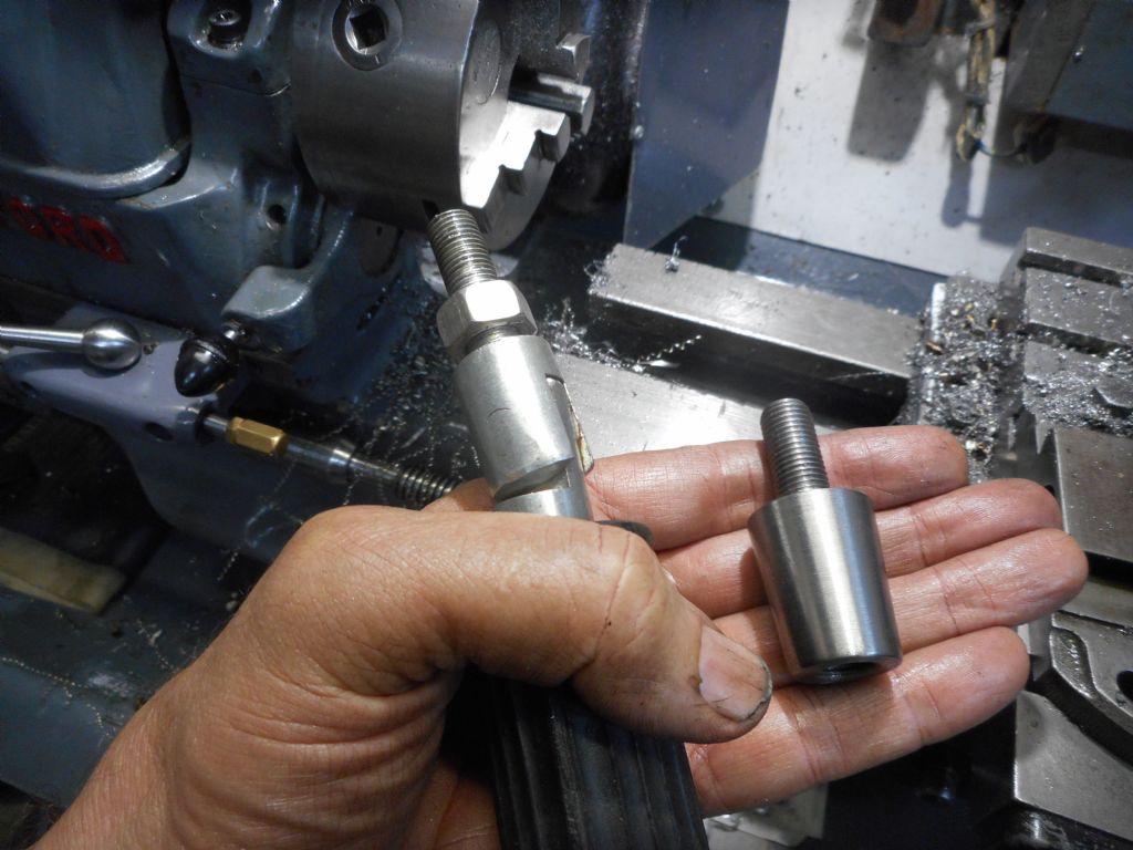
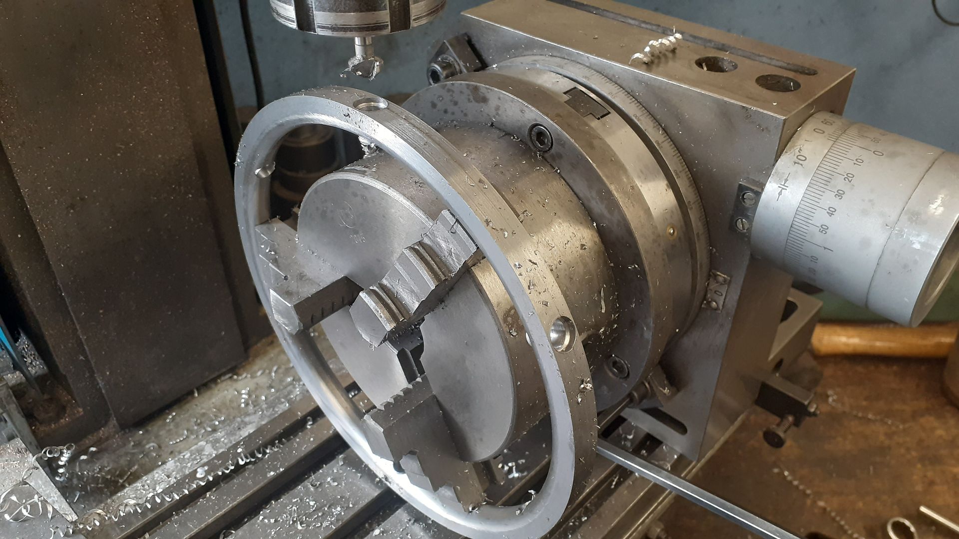
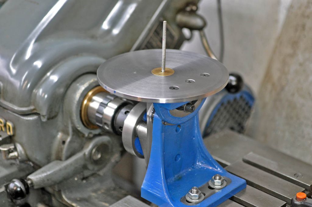
Decided to have a go at making a new one from aluminium so made up a broaching bar and ground down a bit of HSS to match the spline shape. Made up a clamp of sorts to prevent the spindle from turning.
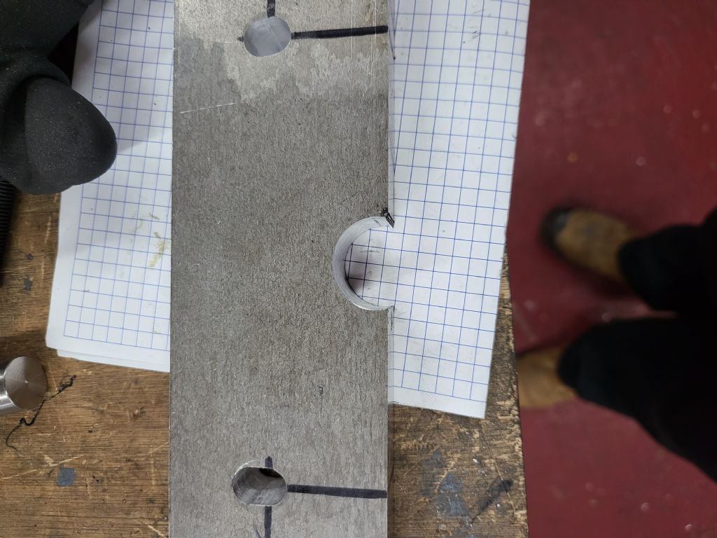
The hole on the aluminium plate was drilled off centre to allow the edges to fit into the splines and stop the shaft from rotating to allow mw to cut the new splines.
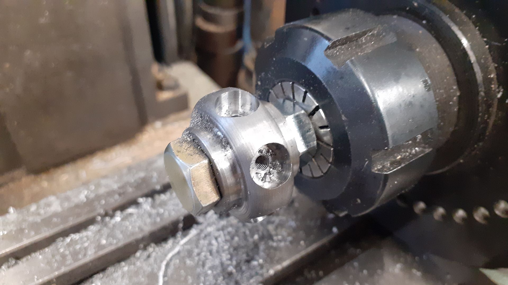
Carried on and cut the drive dog not realising that the cutting tool was slightly off square to the drive dog so the splines are a bit wonky but it still fits and works ok.
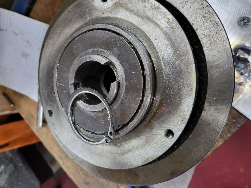
Cut the groove in the drive dog to allow it to be held by the same circlip that holds the bearing cover plate in place.
Greased up the bearings while it was apart and fitted the new drive dog and all is well again. First spline I`ve ever cut and happy that it works besides being a bit off.
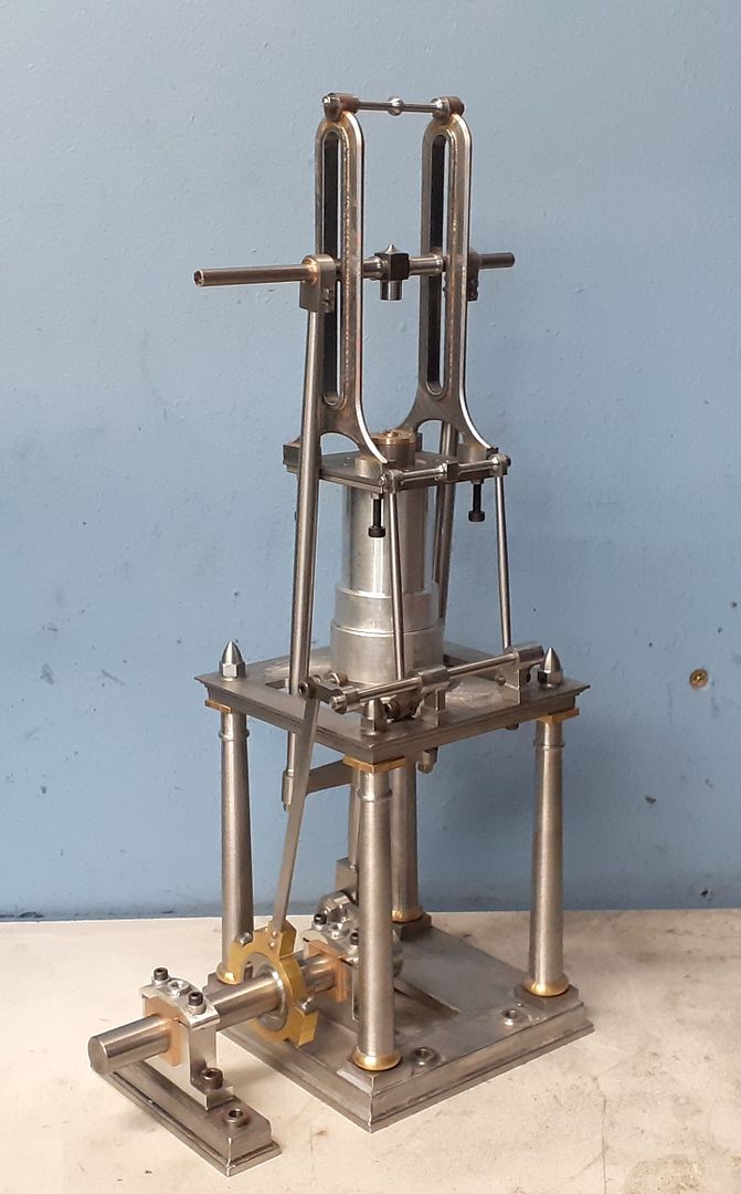
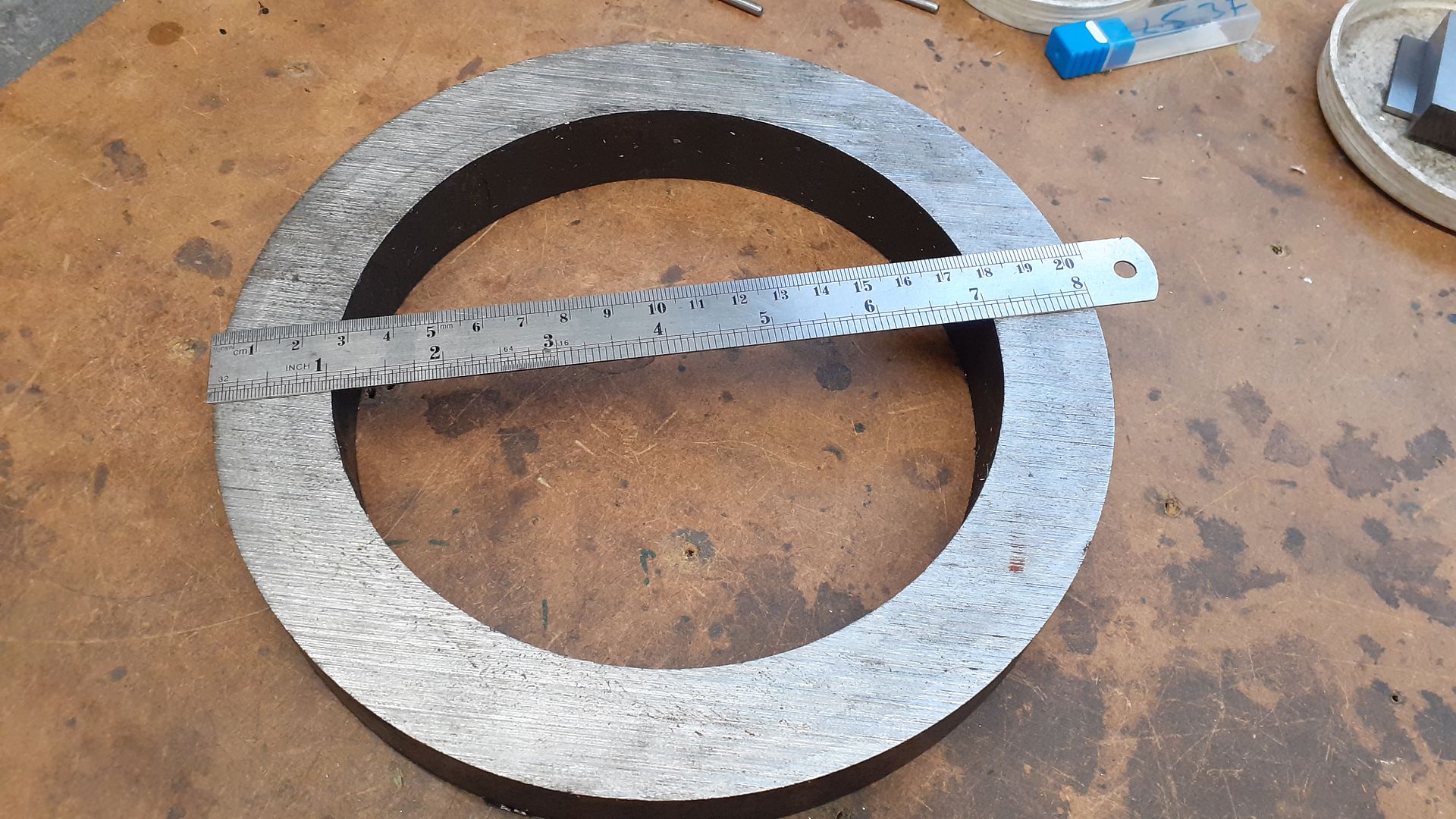
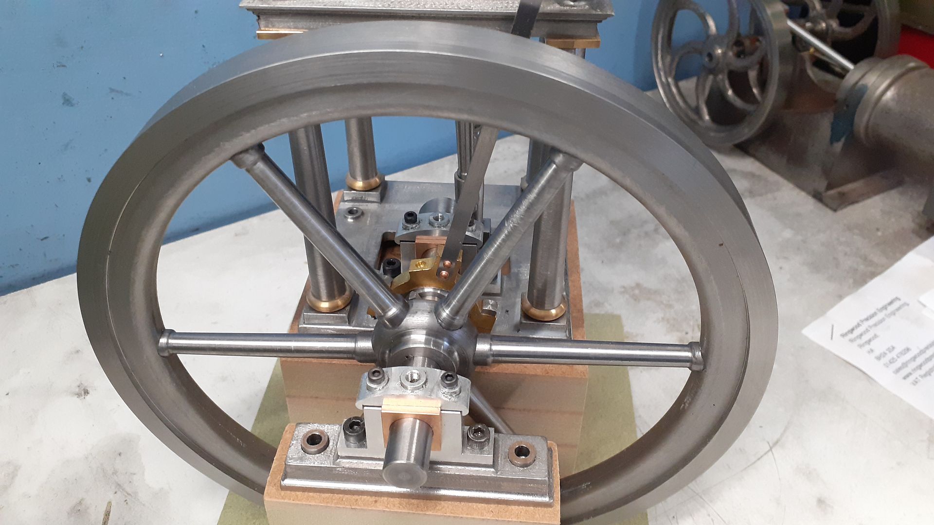
I've made reasonable progress with my much modified James Coombes over the festive break. Just waiting on the cylinder casting which will be the only one used and I've also got to fabricate the 200mm flywheel and that will be it about done.
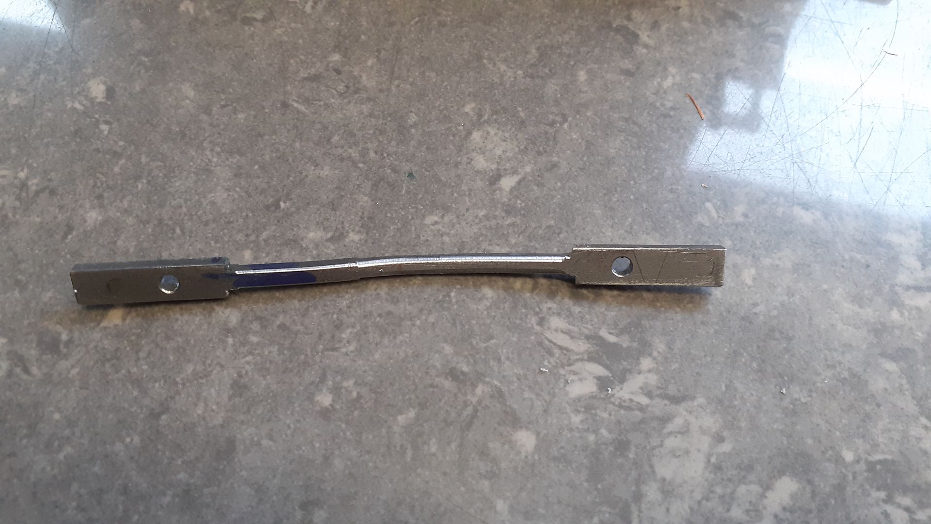
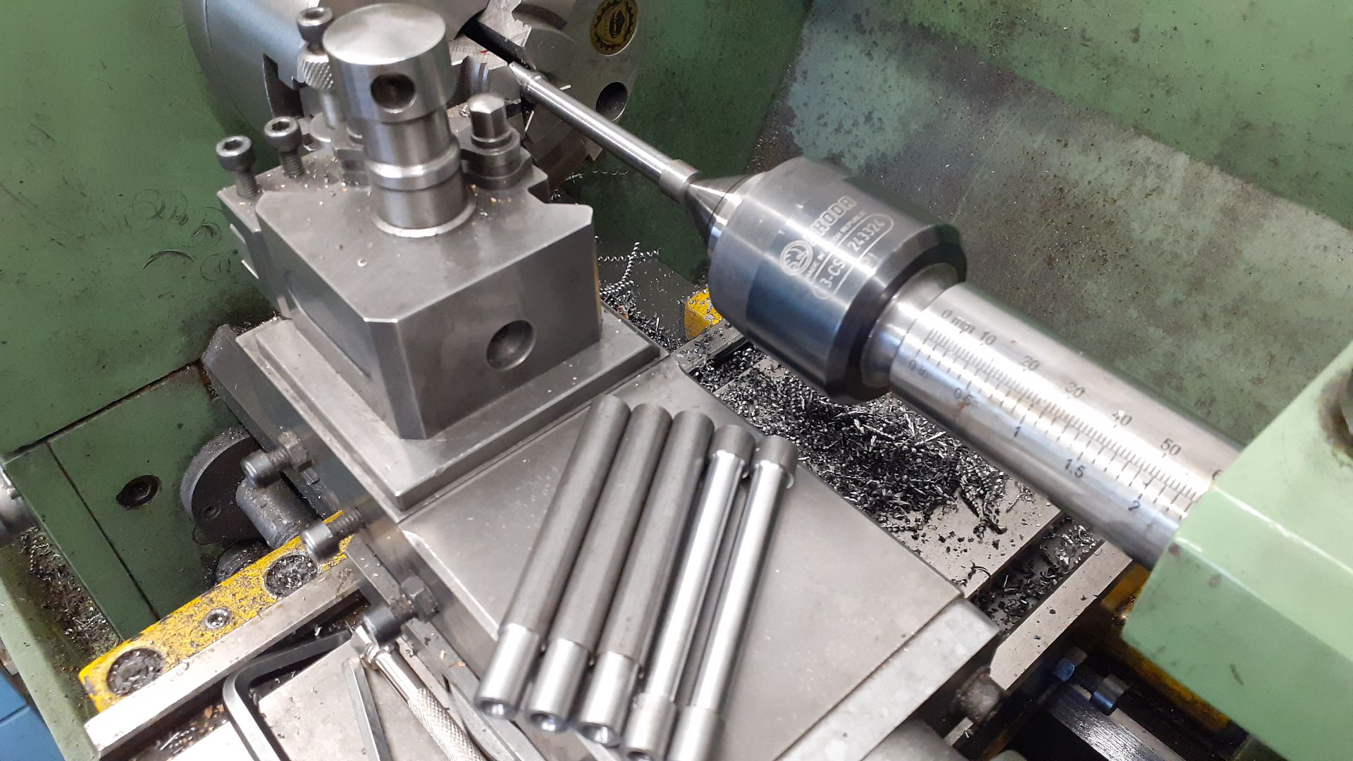
Only one scrapper, I milled some 3mm sheet down to 3×6 to make the valve lifting rods but it was a bit gummy and let go while turning between ctrs. Second set from round bar turned out OK
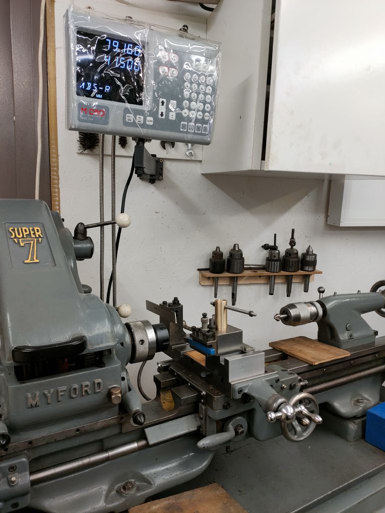
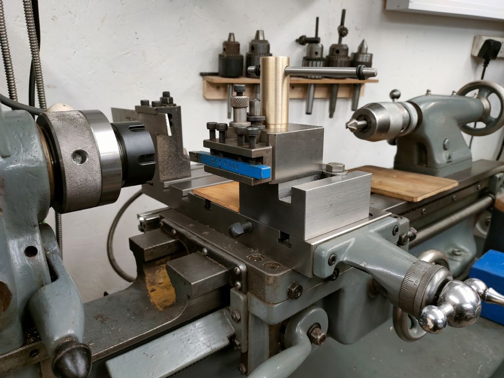
In the pursuit of better accuracy and to follow on from the recent DRO, I fitted a ER32 chuck and a solid tool post in place of taper turning slide.
I discovered more gaps in my knowledge…
7mm twin flute still got pulled down in an R8 collet – which had been tightened this time. I'm not sure what an appropriate depth of cut/speeds/feeds is but I know it I took too much.
I can't power-tap M10 or even M6 in steel. If I hold tap in chuck then either tap spins in chuck or chuck spins on arbour. I will get a new sharp tap that fits a collet and give it a go.
I fitted the ER chuck with less than .01mm runout measured on the body, but 0.05mm on the taper. After skimming the taper I got it to less than 0.02 which will do for now until I feel I know better what I'm doing (the cutter was screeching which suggest something wrong) . Putting a 10mm mill in a collet gives .06mm runout – a little from the mill, but most from the cheap collets (cheapest set available). I will get a few better quality collets in specific sizes.
The 63mm shell mill I got for Christmas works a treat. Makes me think I should have gone for 80mm.
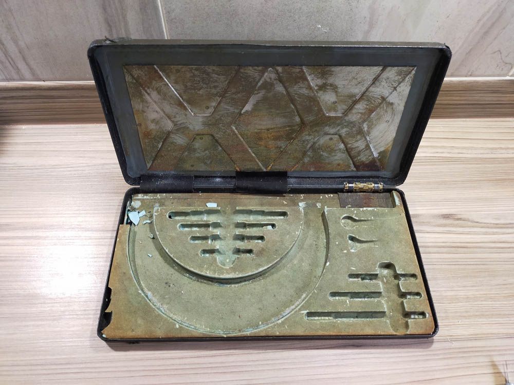
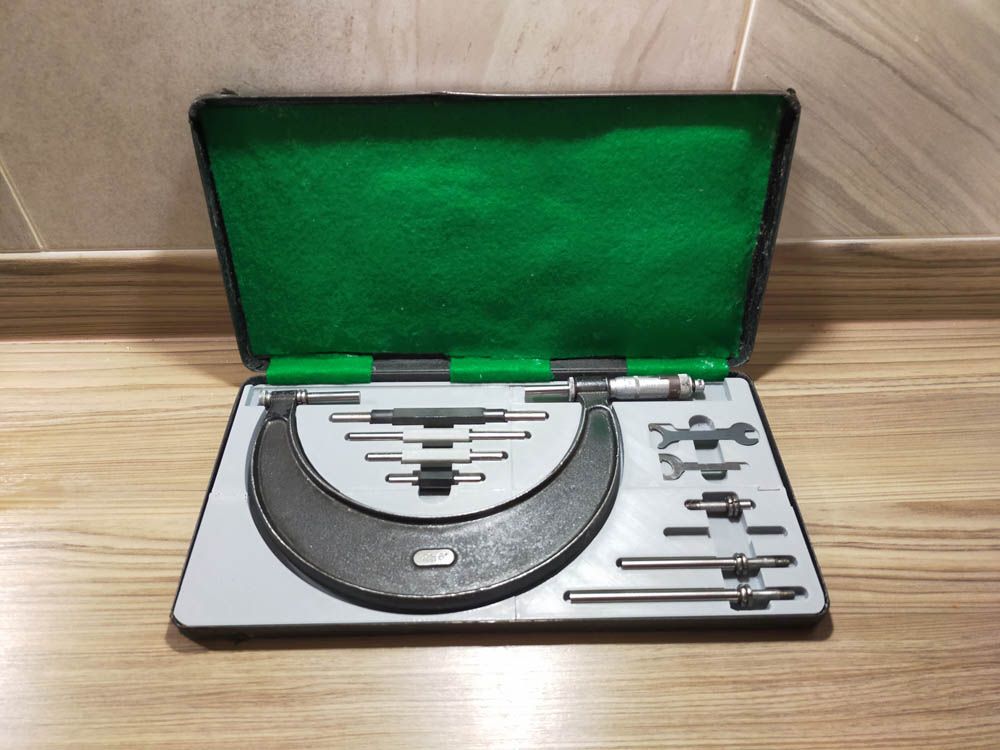
I was fortunate enough to be the only bidder for a 2-6" M&W micrometer on ebay. The blown plastic case liner is in a bit of a state
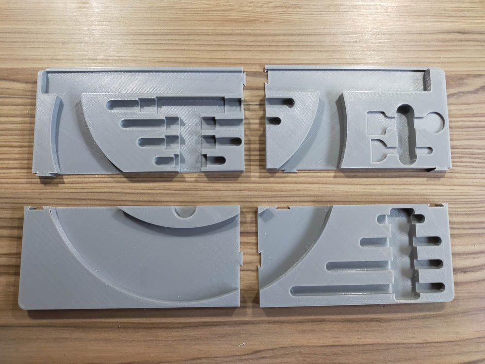
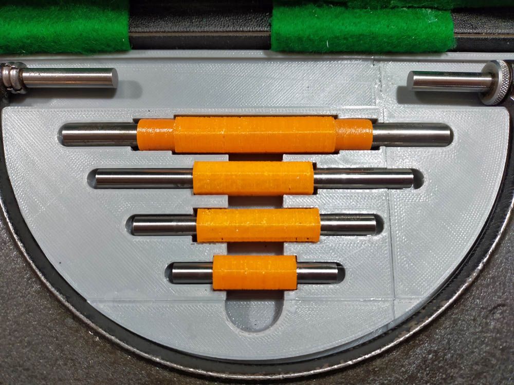
My 3d printer is not big enough to print the whole thing, so divided into 4 bits
Not sure now about the felt pad in the lid – might harbour damp. 2 of the collars for the standards where missing so I have printed those from PLA. The originals are rubbery so I will have a another go with TPU though not confident of success.
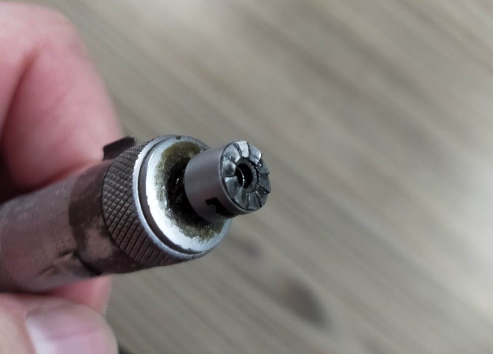
The ratchet thimble is missing from the micrometer head. Although I never use it, I feel it ought to be there. I guess I will have to make a matching ratchet to this
The 2 original black collars were both loose so I printed all 4. Took a few attempts to get the TPU parameters (nearly) right. I think my filament may be a bit damp but I'm happy enough with the result.
There is a first time for everything. Making the tapered footpeg spacer block for a motorbike project, I knew I needed the taper to go from 1" to .880" over a distance of 1-1/4" but did not want to stop, wash my hands and either do the trig or look up an online triangle calculator to set the topslide angle. or set up a dial indicator to set it up on the job.
So I turned the first 10 thou on the end down to .880 diameter and then set the top slide angle by eye, just guestimating from the edge of the topslide vs edge of the cross slide that it seemed to taper about the required .110" over about 1.25". I figured I would adjust maybe once or twice as I went, in order to get the dead correct angle. Near enough for a spacer hidden away under a greasy motorbike anyway.
But blow me down, it worked out PERFECT and I mean perfect. The tool just kissed the .880" step at the small end on the start of the final cut and the cut ran out EXACTLY at the other end of the section. It'll never happen again. I should have gone straight round to buy a lotto ticket.
Got some more done on the Hemingway Kits large bore steady rest.
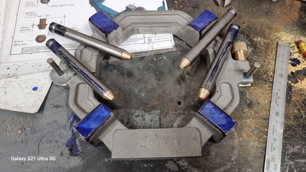
Made the Phosphor bronze fingers & pressed them into place.
Steve.
Looking good Stevie. What diameter are those steel fingers? And about how long are they? I might get around to making my own fabricated knock-off sometime.
Nice one Jason, fantastic work yet again, but question.
The spokes look as if they are in pockets so on the hub, did u do one of each radial pair shallow for a “bottom sizing fit” then slip the other on an over deep pocket and glue in place? I assume they are either screwed or pegged at the rim
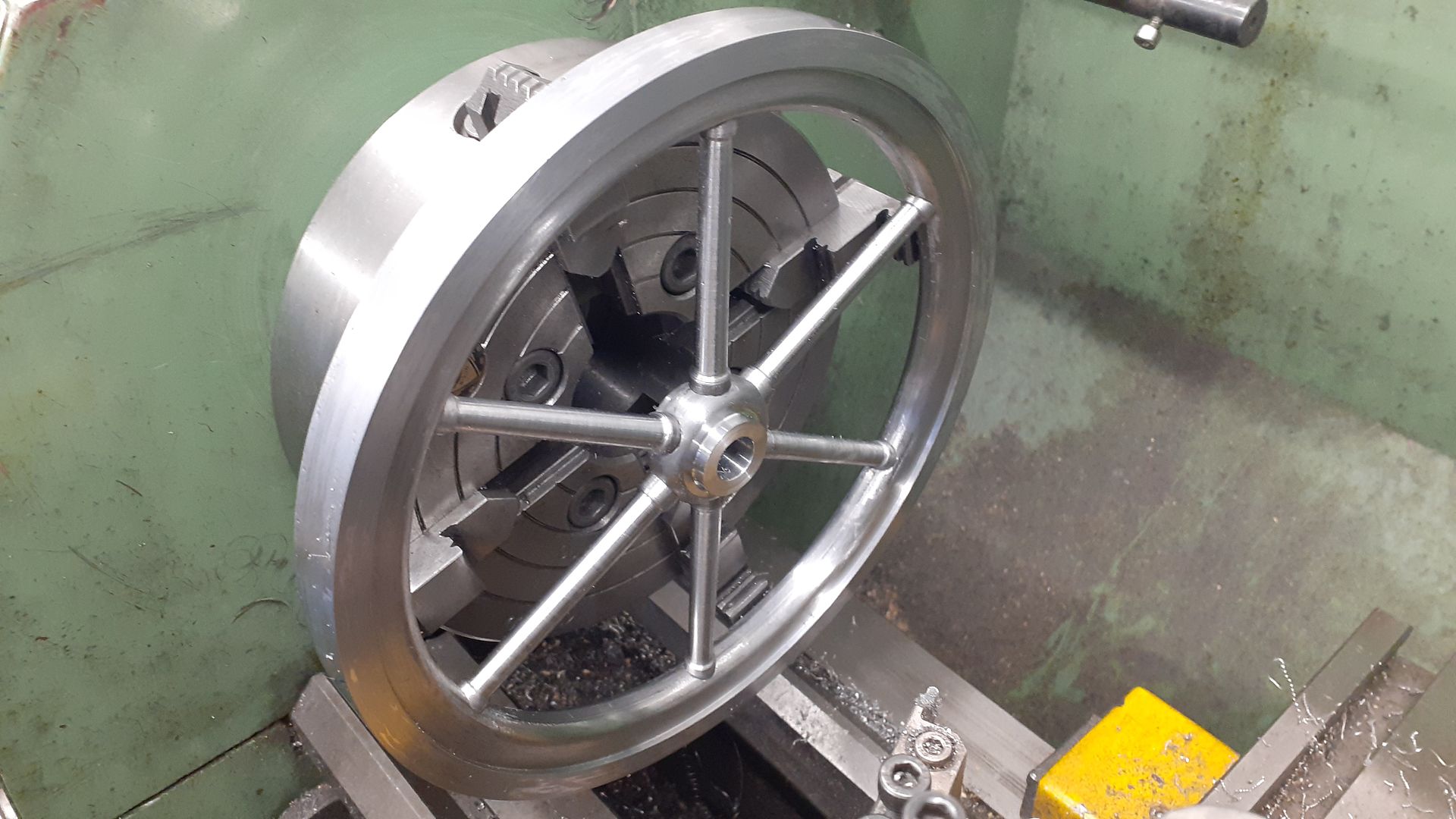
Zan, first I turned an outer rim from 1/2" wall tube with a 0.25mm step on the inner face
I then turned the inner rim from the piece of 1" wall tube to fit inside the outer ring. I was able to part off the piece I needed and save the other bit for something else, left the last 0.5mm of wall to cut with a hacksaw
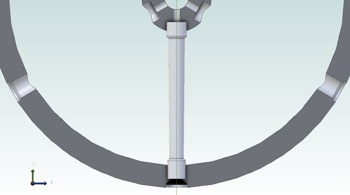
The inner rim was then drilled 9mm for the small end of the spokes and countersunk
The hub was turned from 35mm stock, rough drilled 10mm and then drilled and tapped M4 with a counterbore for the larger 10mm dia ends of the spokes
Spokes were from 10mm dia stock, faced to length, ctr drilled and the ends tapped M4 (hub) and M5 (rim) before reducing one end to 9mm dia and finally taper turned
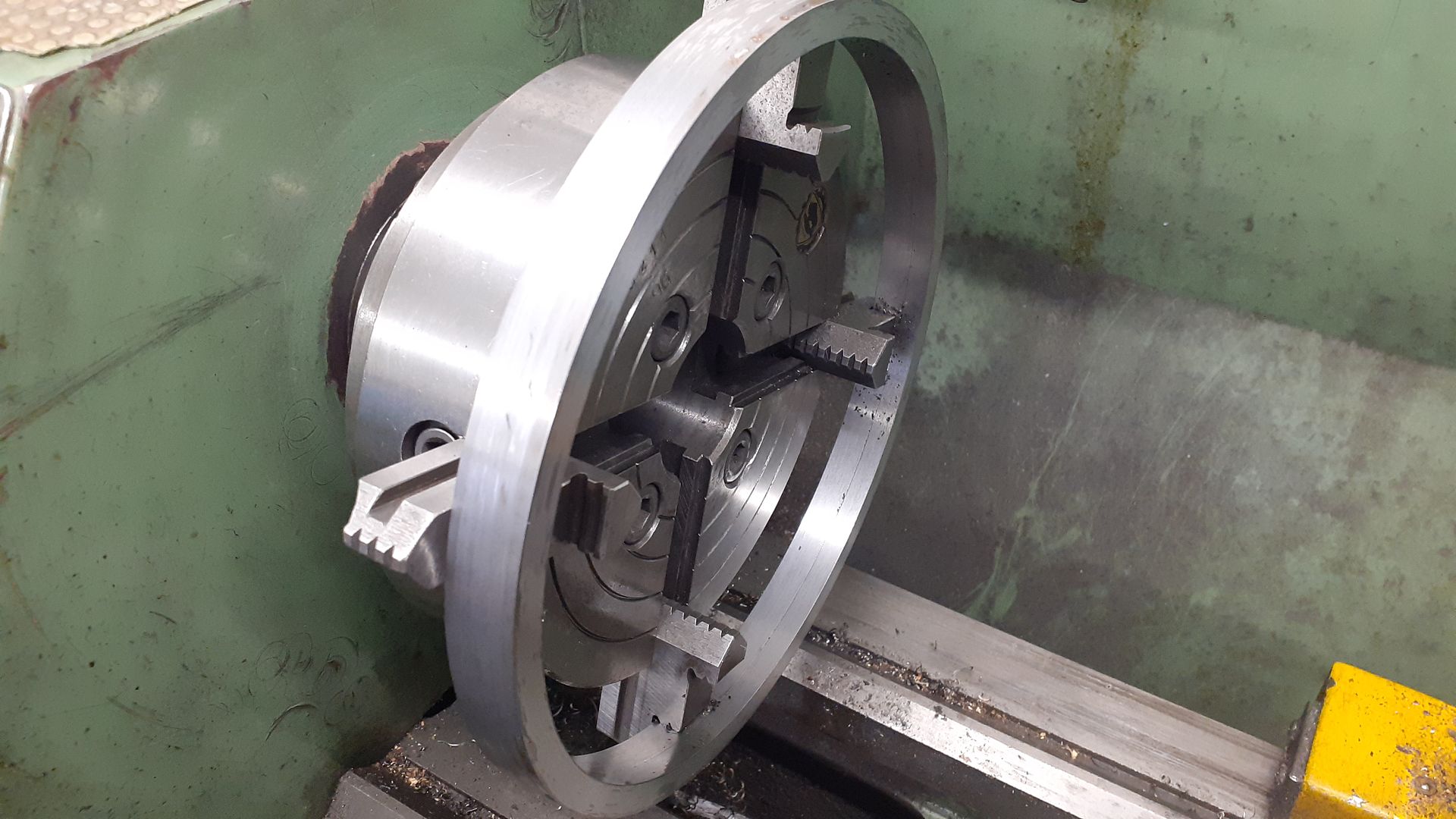
I got carried away and did not take an assembly photo but basically the inner rim was held in the 4-jaw, spokes slipped into the holes, hub then supported on a bit of 10mm rod held in the tailstock chuck.
M4 studding in the ends of the spokes allows them to be screwed up to the bottom of the hub counterbores with a smear of JBWeld. M5 csk socket screws then screw into the other end of the spokes and seat against the csk holes. Final hub position can be adjusted by how tight these screws are done up – a bit like truing a bike wheel. Smear of JBWeld on this joint too
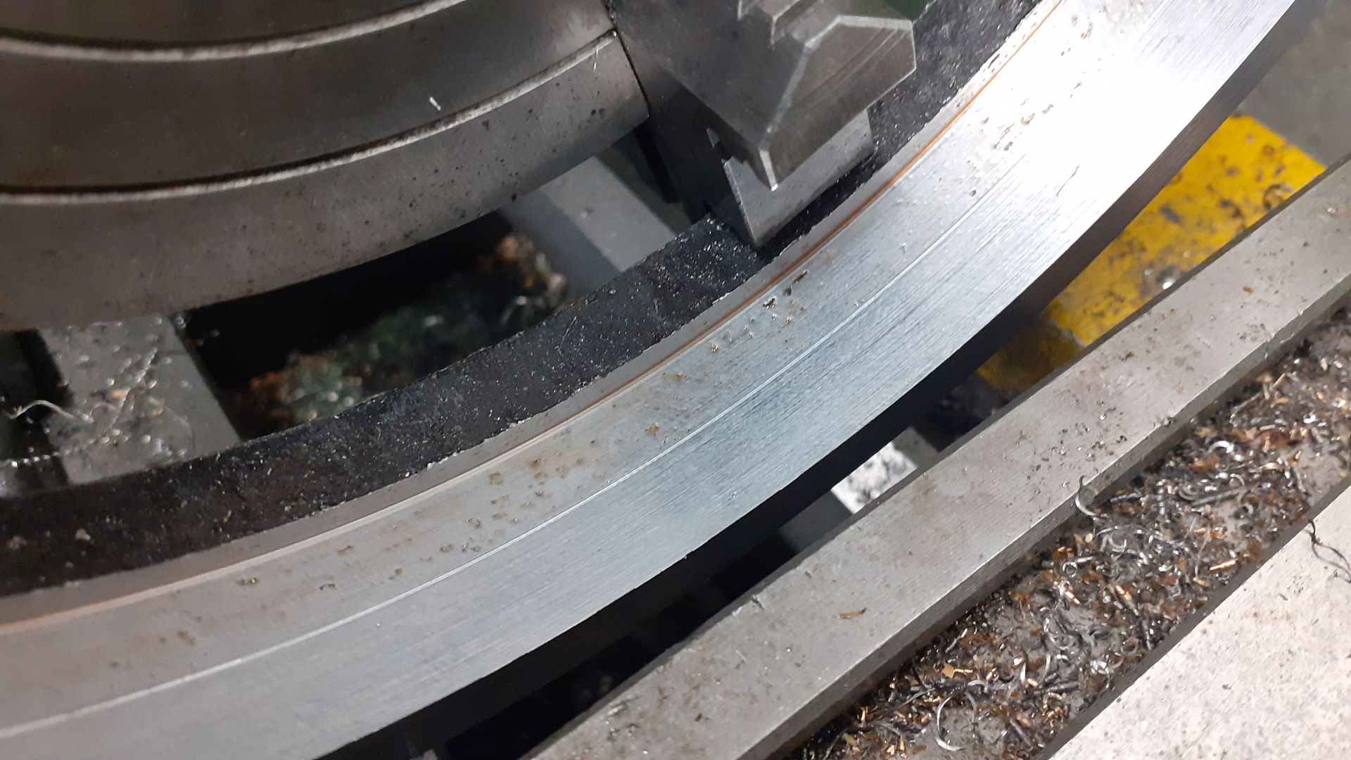
The two rims were then slid together with the step previously turned ensuring the inner ring is sitting true and equal about mid point of the outer rim. Loctite used for this joint. Doing it with the inner and outer rim allows all the holes to be hidden.
Once set back in the 4-jaw for a final skim and bore hub to final size, then broach keyway. I still have to add a small fillet of filler around all the joints for that "cast" look
A little something to produce some swarf while the paint on James Coombes II is drying. Still needs a second setup to get at the underside of the bit on the right.
Got some more done on the Hemingway Kits large bore steady rest.
Made the Phosphor bronze fingers & pressed them into place.
Steve.
Looking good Stevie. What diameter are those steel fingers? And about how long are they? I might get around to making my own fabricated knock-off sometime.
Edited By Hopper on 10/01/2023 11:53:17
Hi Hopper. The complete build is here part 1 of many. If you find it a bit boring just skip through. It turned out fantastic. Already used it on another project & I'm sure once i get used to it then a bonus for the workshop.
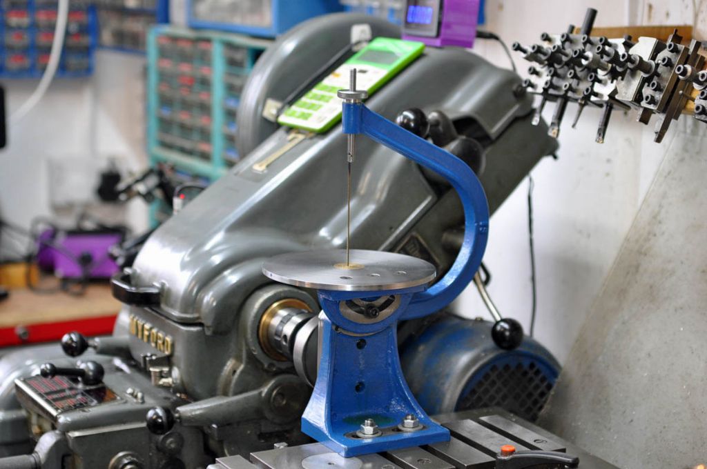
Nicely finished. I did one of those mainly for the filing function. I should really finish the bow for the saw blade but had a little trouble working out how to hold/register the casting in order to get the bores for the tensioning screw threads in line. I must admit to not spending too much effort to work it out and put it aside ‘until inspiration strikes’. It’s still there actually.
Maybe I’m being too finickity and it’s not that critical but I would be interested to hear how you machined yours. It’s an odd shape to hold actually.
I followed the instruction to to drill the hole with the drill in the headstock chuck and pushing from the tailstock, then sawed off the square filler piece. I used a length of 1/4" silver steel through both holes to give me a reference and then clamped to the mill bed with padding under the head, using a DTI on the steel bar to ensure orthogonality. I squared up the top and bottom faces of the rectangular boss (as seen when the bow is in operation). I was then able to hold the bow in a vice to mill the boss to the correct thickness and drill and countersink the holes.