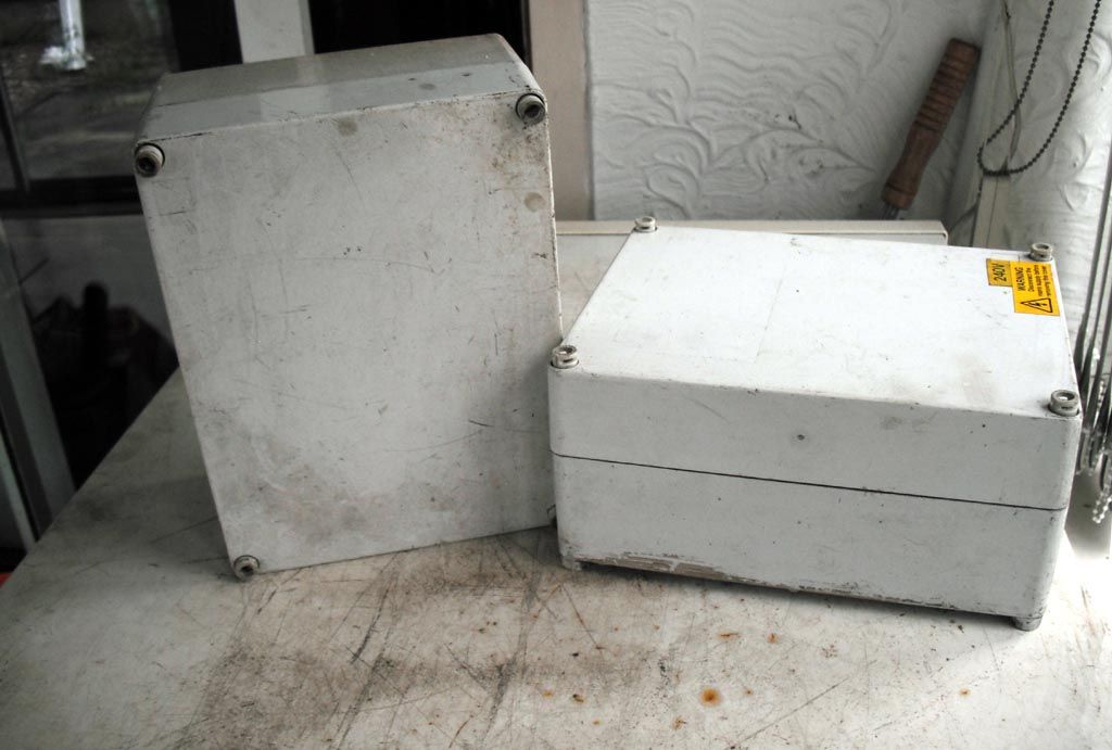
I recently finished converting my lathe to a 3 phase inverter/ motor drive. I've had had no luck finding a suitable enclosure for the inverter. Those that are deep enough are far too big in height and width. I had a dig round in my old installation gear and found a pair of boxes about right for height and width, but not deep enough.

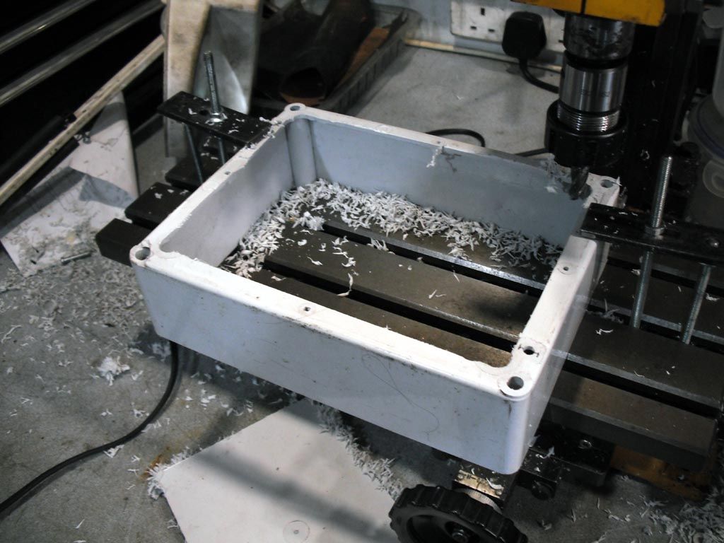
Measurement showed that stacking the boxes on top of each other would give sufficient depth. So, onto the mini mill and remove the back from one box. I did it this way because I'm hopeless at cutting straight lines with a handsaw. I also machined off any sticky-up bits to give a flat surface.

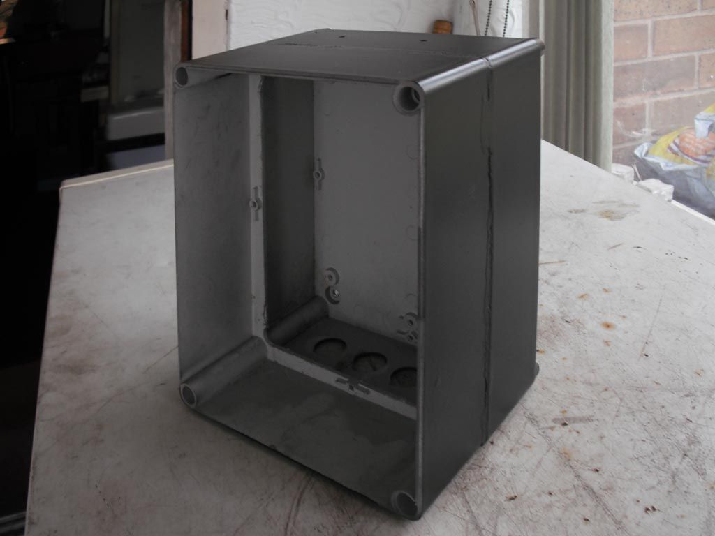
Using plastic rods in the corner holes for location and strength, the boxes were glued together and when set, undercoated and then sprayed black

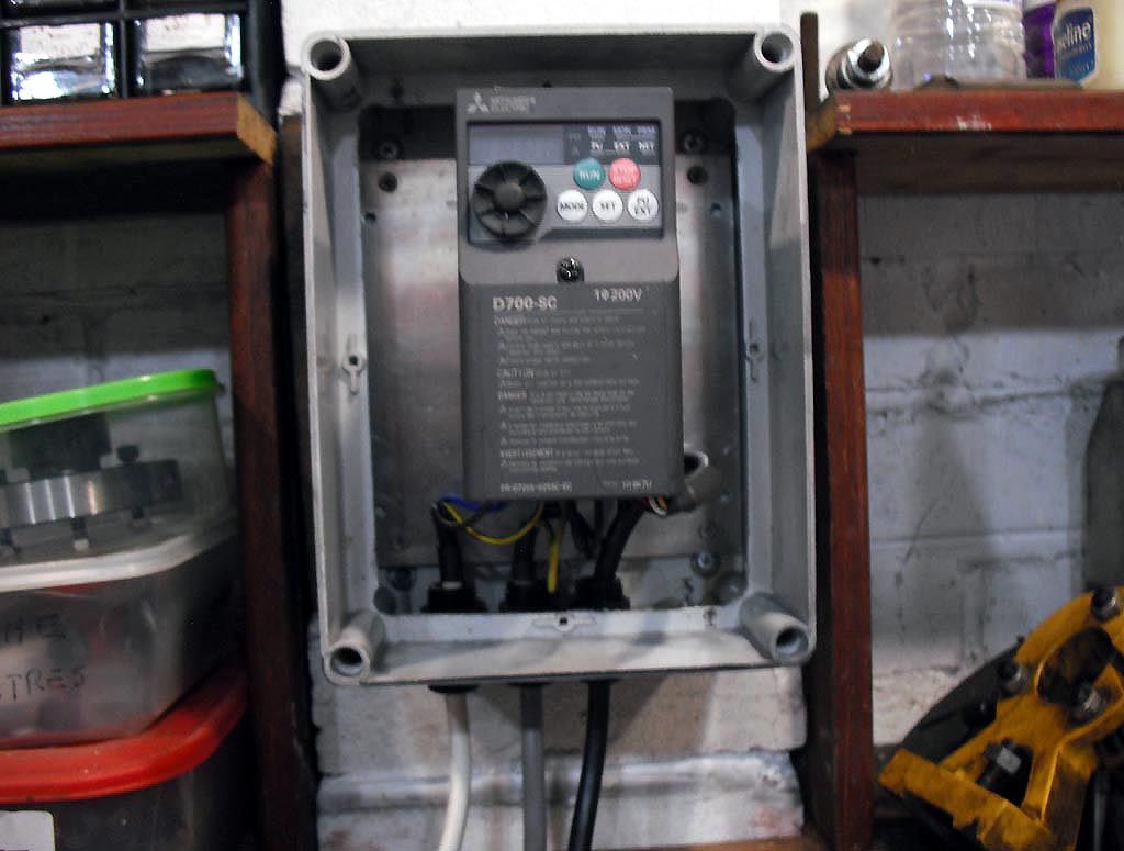
Fitted the inverter on the box's metal back plate and fitted it in the box. It looks off-centre in the photo but that's down to the camera angle.

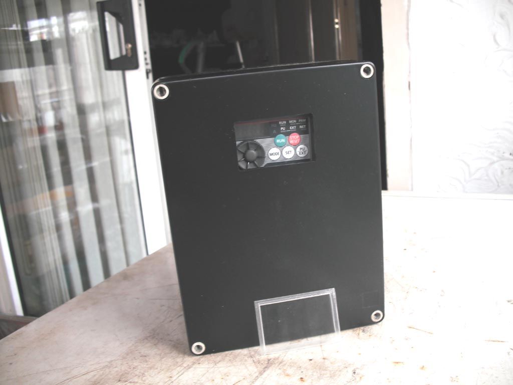
I then tried the lid which was already prepared with a window cut for the inverter display and then sprayed. The piece of Perspex for the window is at the bottom of the picture and just needs gluing in.

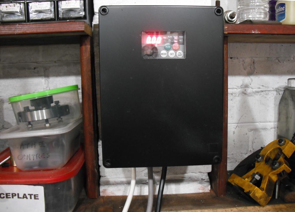
I now have to fit the cable glands, wire it up (again) and fit it on the wall. That's the easy bit. I then have to decipher the programming instructions which came on a CD with a 301 page PDF document. It did come pre-programmed, but I need to increase the maximum frequency (currently set at 50Hz), so I can get the full range of speeds on the lathe. Hopefully that will be relatively easy to do.
 JasonB.

