The Workshop Progress Thread 2020

Advert

The Workshop Progress Thread 2020

Home Forums Work In Progress and completed items The Workshop Progress Thread 2020

Viewing 25 posts - 176 through 200 (of 284 total)
  • Author
    Posts
  • #478255
    Ex contributor
    Participant
      @mgnbuk

      A frustrating weekend in the garage / workshop for me.

      I volunteered to make a chuck adapter for one of my wife's work colleagues, who dabbles in wood turning. His lathe has an M24x3 spindle nose with 24mm register & he wants to fit a chuck with an M33 x 3.5 thread & 33 mm register. There are M33 to various nose thread reducers available but not to M24 x 3, which doesn't appear to be a popular size.

      First trip-up was yesterday afternoon, when the lathe inverter refused to start up again after a coffee break – Fault Led illuminated. This is an ancient Toshiba inverter that was used and obsolete when I was given it, probably around 20 years ago so I can't really complain. A quick check with a basic multimeter showed balanced motor phase winding resistances & no obvious shorts to earth, though I need to bring my insulation tester home to be sure. I have a number of suitable NOS inverters in storage, but was uncertain whether or not to reform the capacitors before use (they have been is storage for several years) – a bit of researching suggested it might be wise to do so.

      Tried the lathe again today & it worked ! Got the part to the stage of cutting the M24x3 internal thread & trip-up number 2 came along – the 34 tooth gear I bought to use with the Myford QC gearbox couldn't be fitted, as the gear quadrant would not rotate far enough (hit the end of the slot). A quick check found that I have all the gears required to cut a 3mm pitch thread with the "official" metric conversion set for the the Myford QC gearbox – but not the spacer to clamp up the gear on the gearbox input shaft. Got one on order from Myfords now. I tried to run the lathe to check how the gear train sounded under power (seemed OK by hand), but the inverter faulted out again.

      So I lashed up a 240v to 55v-0-55v transformer & put 55v into the NOS Trend inverter for an hour, followed by 110v for an hour and a half (the drive came to life on this reduced supply), then 240v for an hour. No problems so far, just need to fit it after checking the motor out. I'll put switches on this one to control the spindle direction – the Toshiba was just linked up to sit at a constant 50hz forwards on power-up.

      Nigel B.

      Advert
      #478343
      Ron Laden
      Participant
        @ronladen17547
        Posted by JasonB on 07/06/2020 16:58:08:

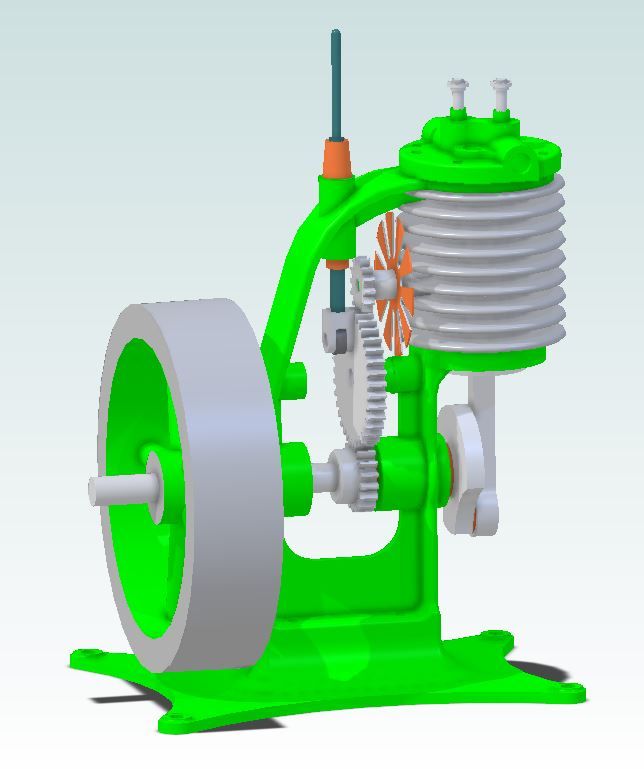
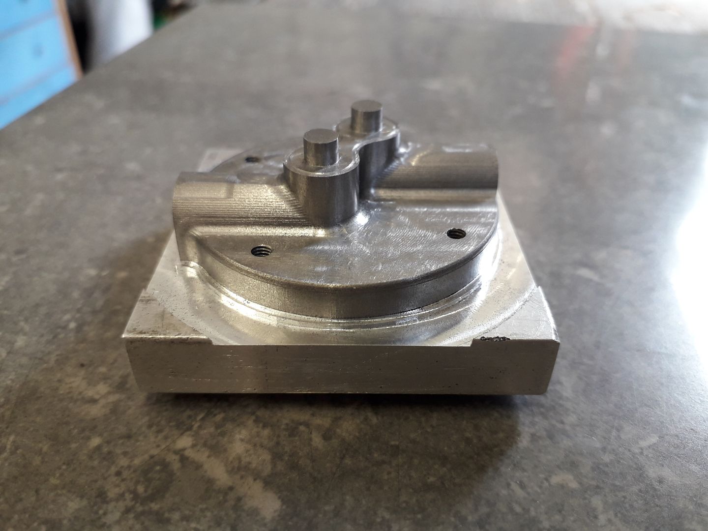
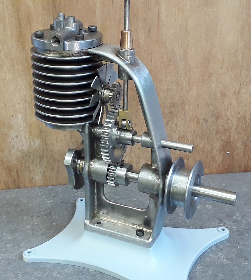
        I've made a start on the next engine, loosly based on a 1946 Thompson model engine.

        Morning Jason,

        Looks like another shapely engine is on its way, is that an aluminium cylinder.

        #478344
        JasonB
        Moderator
          @jasonb

          Hi Ron, The original had what you see there all cast as one in aluminium, I did think about hacking it out of a solid bit of 6082 on the CNC but in the end opted for a silver soldered fabrication so what you see is all steel. Like the original there will be a cast iron liner and I will also use CI for the cylinder head rather than a bronze casting.

          This is an original (or Bob herder kit)

          And where I'm at with the drawing.

          render.jpg

          #478346
          Ron Laden
          Participant
            @ronladen17547

            Interesting Jason, I like the way the valves are driven via the gears and the pushrod, is it sized to your favoured 24mm bore.

            Re having a cast iron cylinder liner, is steel not good for cylinders hence having a liner.

            Will follow with interest.

            #478347
            JasonB
            Moderator
              @jasonb

              The cam has not been added yet, the gear just keeps the cam follower from rotating as it runs against the side of it. yes 24 x 24 rather than 1" x 1" of the original.

              I could have gone for steel cylinder with a cast iron piston running in it much like a lot of engines do but if there were any distortion due to the soldering the liner will be round.

              #478348
              DiogenesII
              Participant
                @diogenesii

                That Thompson really is an interesting little engine – I can see why you'd want to model it. I'd guess that economy was the main driver of the design, but there's something very pleasing about it.

                Nice, Look forward to seeing it come together.

                #478409
                Ron Laden
                Participant
                  @ronladen17547

                  Jason, do I take it that you will fit the liner and then bore it to size and finish on the mill..?

                  #478755
                  duncan webster 1
                  Participant
                    @duncanwebster1

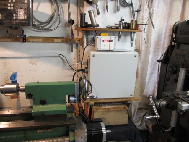
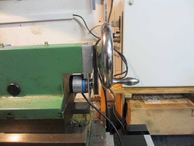
                    My timing belt pulleys arrived from China finally, so I've been making swarf for a change. Tailstock DRO now functional, needs a belt guard and the display putting somewhere sensible

                    img_3781 (small).jpgimg_3780 (small).jpg

                    #478757
                    JasonB
                    Moderator
                      @jasonb
                      Posted by Ron Laden on 08/06/2020 12:40:14:

                      Jason, do I take it that you will fit the liner and then bore it to size and finish on the mill..?

                      Probably turn it all in the lathe and then just slip that in to the finned section, might need a bit of a clean up first?

                      #478804
                      Ron Laden
                      Participant
                        @ronladen17547

                        Looking good Jason, I see you have it well set up to prevent distortion. Is there much movement when silver soldering steel, I guess a lot depends on the assembly and how much soldering there is.

                        #478807
                        JasonB
                        Moderator
                          @jasonb

                          I've noticed it more on round items like wheels and flywheels where the rim will open up and you also need to watch out if anything is clamped together as the pressure can distort the soft hot metal brass and bronze are more prone to this as you are getting closer to their melting point,

                          I tray and build in machining allowances on critical surfaces so end up with something like a casting that can then be machined. For example the two horizontal circular parts will have the reduced diameter middle removed which served to keep them in line but reduced mass so they heated quicker, the ends will be skimmed and then holes bored. he two vertical parts of the frame are mostly parallel sides at the moment to make holding for machining easier after which they will be reduced in width but will bulge out around the crankshaft bosses and also have all the corners rounded over.

                          #479016
                          Neil Wyatt
                          Moderator
                            @neilwyatt

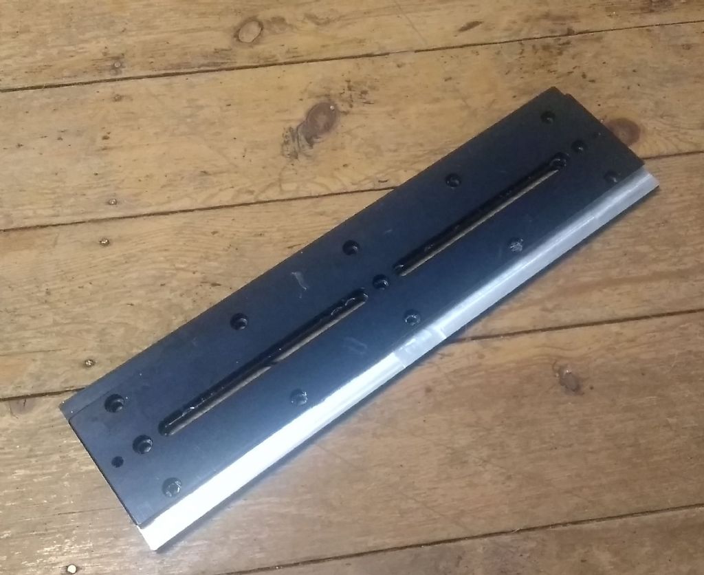
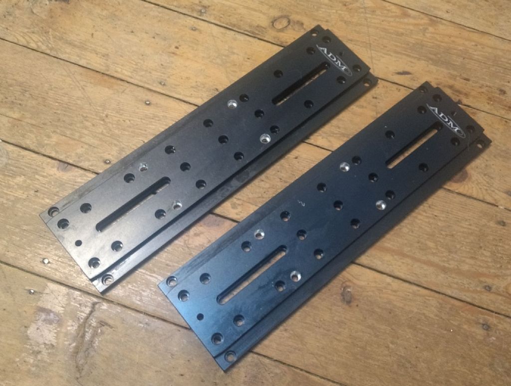
                            Two jobs yesterday, curiously related as they both involved 'Losmandy-style' telescope mounting dovetail plates.

                            I don't think I've even handled one of these before a few days ago, and then two friends got in touch independently asking me to modify theirs! Both sets dropped off at the garden gate with appropriate social distancing, but good to see some familiar faces.

                            These plates can be ridiculously expensive, especially red-anodised Italian ones, so it's not surprising that one chap had gambled on a cheap 'no-name' dovetail. The problem was that the distance across the dovetail was at least a millimetre wider than the slot in the saddle clamp it had to fit…

                            An inspection of a 'proper' dovetail showed that (unlike the narrower, deeper Vixen-style I've made before) it is a 60-degrees, so at least I could use a standard cutter. Offering the cutter up to the cheap plate showed an issue straight away – it was cut at nearer to 70 than 60 degrees. That's why the distance across the dovetail didn't seem much oversize yet it clearly was nowhere near fitting.

                            I should have skimmed both sides, but the problem was that it's around 400mm long and that meant interrupted cuts anyway. I decided just to skim 1.5mm off one side. The slots made it easy to clamp although I could only use M6 screws, and I had to remove the Y-handwheel and rely solely on power feed. I used block against the t-slot for alignment.

                            Locking the Y-axis the Bristol handle broke – and it was a 'superior' replacement for the one originally fitted. I swapped the handle off an M5 one to get it going again, but I'm going back to using a cap head screw and a t-handle Allen wrench…

                            I decided better t take a light skim off the flat than end up with a step inside the dovetail vee, but it was a fairly light cut.

                            I'd forgotten that some time ago I fitted a 1A fuse as a 'get running' bodge, so 40mm into a cut under power feed it blew… (for the record I was climb milling on my X2).

                            But I had a pack of the correct (I hope) 3.15A fuses and managed to complete the first cut. I then moved it along again using blocks to set it. As I feared despite care being taken to get the same Y setting, I got a very slight bump at the join. But this is just a clamping dovetail, not a working surface so that's not a problem.

                            I also discovered a second reason why these plate are cheap – the countersink holes are FAR to widely spaced and my cut just broke into the countersinks at the base of the dovetail. Even if machined symmetrically there would only have been about 0.25mm between dovetail and countersinks…

                            Naturally there are machining witnesses where the mill stalled and at the join, but you can't really feel them.

                            I broke all the sharp edges and it's now a nice fit in the dovetail clamp.

                            losmandy dovetail 1.jpg

                            The other friend's pair were a budget set, and the irony was that the countersunk holes were too close together, by about 4 or 5mm, for expensive red tube rings! Not necessarily a fault as different manufacturers use different spacings. The chap is ex-Royal Engineers, but although his expertise was building bridges in Iraq at 40C in the shade he was still able to accurately mark out the positions for four holes on each dovetail.

                            This was a much easier job, and the drill press was up to the task. I picked up each of his marks with a spotting drill. the holes were an odd size (meant as clearance for both M6 and 1/4" UNC – camera tripod thread). It was rather less than 7mm and the closest match I could find was letter I, which I followed up with. Deburrd the exit wounds and a test against the tube rings showed all was well. They are countersunk M10, and while strictly they should be flat bottomed, rather than risk a mishap I just followed up with a quality M10 bit and used the depth stop on the drill press, then deburred the top.

                            losmandy dovetail 2.jpg

                            The moral of this story?

                            If you're a member of an astro club, don't let on that you have a workshop!

                            Neil

                            #479024
                            Joseph Noci 1
                            Participant
                              @josephnoci1
                              Posted by Neil Wyatt on 10/06/2020 22:15:38:

                              The moral of this story?

                              If you're a member of an astro club, don't let on that you have a workshop!

                              Neil

                              If you're a member of an astro club life, don't let on that you have a workshop!

                              Joe

                              #479187
                              Jim Nic
                              Participant
                                @jimnic

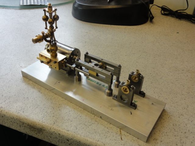
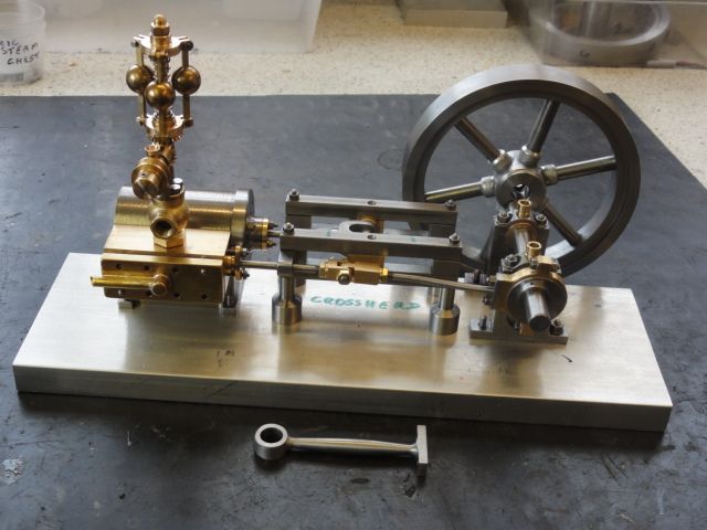
                                A "family shot" of progress so far on my version of Stew Hart's Dads & Lads mill engine.

                                family 1.jpg

                                The governor is a Bangood special .

                                There's still plenty to do; when I've got the eccentric and flywheel done I will look to getting the crankshaft drawn up so that I can fit a driving pulley that lines up with the governor.

                                Jim

                                #479191
                                Chris Gunn
                                Participant
                                  @chrisgunn36534

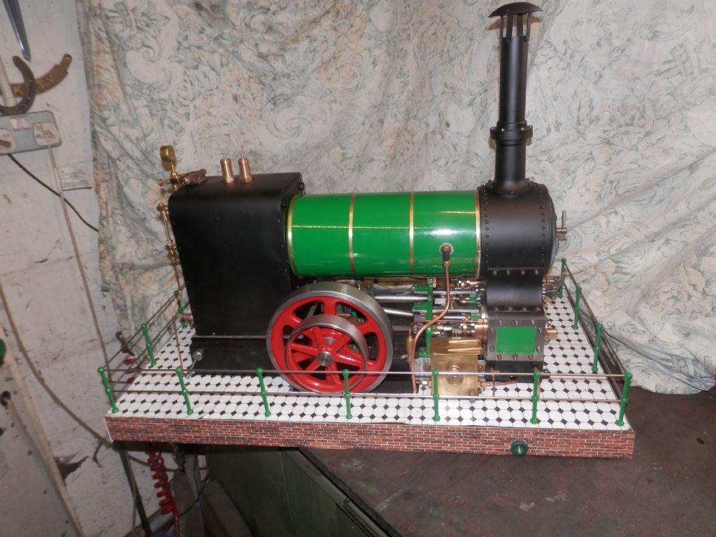
                                  Here is my Undertype now painted and with a tiled and bricked plinth. I used printed glossy tile paper and embossed brick effect paper, but I should have done it Jason's way, as the oil from the engine is working its way under the paper. Chris Gunnp6114015.jpg

                                  #482838
                                  Iain Downs
                                  Participant
                                    @iaindowns78295

                                    Nothing as nice as some of these models, but this weekend I completed a spindle lock for my mill

                                    spindlelock.jpg

                                    As usual for me, the original idea (to have the legs a snug fit to the DRO link) failed, due to slight inaccuracies in the centering of the block on the cylinder. Bodging didn't work, so I ended up reversing the block and putting some set screws in.

                                    It's now helped to make some keyways for me.

                                    Iain

                                    #485214
                                    JasonB
                                    Moderator
                                      @jasonb

                                      My Thompson engine has been steadily progressing. All the gears are in place complete with cam and coolong fan, crankshaft done as well as the liner and piston. Yesterday I shape dthe head on the CNC and this morning did the valve and inlet/outlet holes.

                                      Edited By JasonB on 12/07/2020 14:05:32

                                      #485221
                                      Ron Laden
                                      Participant
                                        @ronladen17547

                                        Looking good Jason, especially the frame considering it came from flat stock, you could certainly be forgiven from thinking it a casting. Also impressive is the alignment considering it a silver soldered assy, not the easiest of shapes but obviously proves your initial set up was good.

                                        Ron

                                        #485358
                                        Jim Nic
                                        Participant
                                          @jimnic

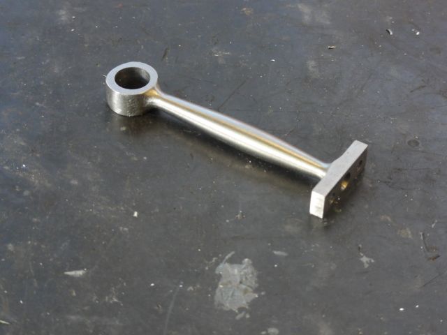
                                          Slowly but surely I'm creeping up on Stew Hart's Dads & Lads mill engine. Here is the connecting rod before I make the big end bearing:

                                          conn rod 2.jpg

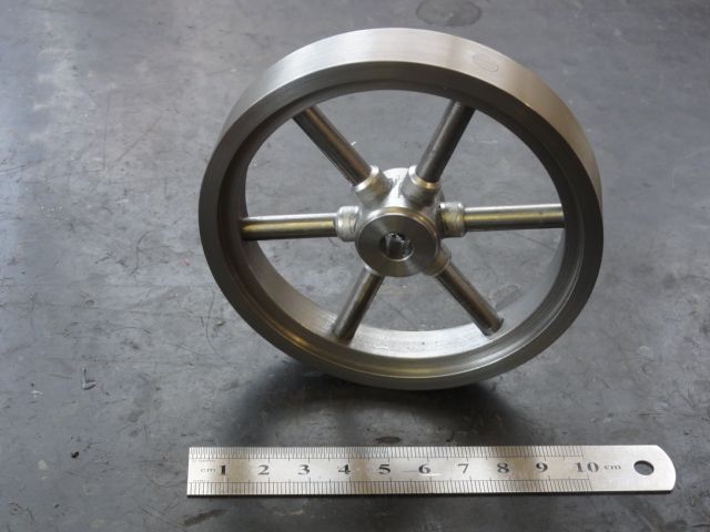
                                          This is the flywheel "Wot I made.":

                                          flywheel 2.jpg

                                          And here's the bits completed so far loosely put together:

                                          family 3.jpg

                                          Jim

                                          #485412
                                          mechman48
                                          Participant
                                            @mechman48

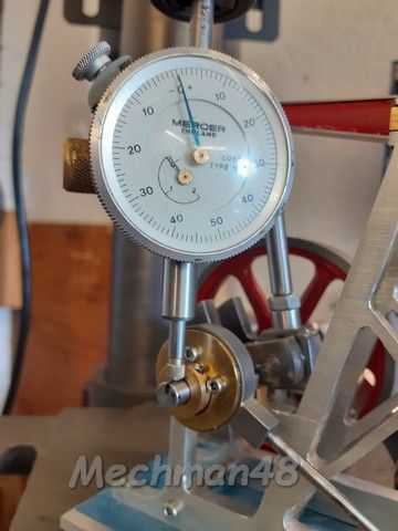
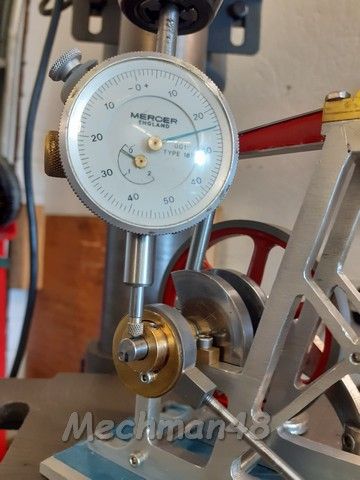
                                            Oh woe is me! got back to my beam engine again after some away time, as previously mentioned, on assembly of earlier parts I noticed tight spots appearing in parts when assembling. one was in the piston operation within the cylinder, I had to strip the piston out & check the bore as there seemed to be a tight spot in the centre of the cylinder ( ? ) don't ask! I ended up giving the cylinder a little extra hone in the middle area to see if that would improve matters, the piston seemed to move easier than before.

                                            I reassembled the cylinder & valve chest assembly together & tried operation with compressed air, it seems to work pretty smoothly, the piston reaching both ends of the stroke when I operated the slide valve so I know that works ok, but when I assembled the eccentric conrod to the bell crank it would not operate through its full rotation. I checked & freed off the end of the conrod yoke where it was catching the bell crank by some judicial filing but still catching as though the conrod was too long & not allowing eccentric full rotation.

                                            I chanced removing a couple of threads from the conrod to see if that would help eccentric go 'over centre' no chance ! finally looked at the crankshaft end; lo & behold .. a run out on one side if the crank. on stripping it out again I checked distance between webs, all as should be but closer inspection showed that the eccentric side of the crank the shaft was not 90* to the web… hmm? it boils down to prior making of the crankshaft the drilling for the 4mm diam portion was not vertical to the web, if you get my drift. Suspicion fell on to the culprit as being the bench drill not being as accurate as hoped ..bearing fit etc.so in essence drilling off the vertical, so in all it was giving me a run out of 0.024" on the right hand side of the crankshaft & locking up the eccentric side plates & over reaching the con rod stroke, Bollocks was my cry!

                                            Needles to say I am now again at the remaking of the crankshaft / webs stage, this time I'll make the crank up as a single rod through the offset ( big end ) & the web end rather than as shown on the drawing as separate pieces; & I'll do the drilling on the mill.

                                            Crank zeroed at 'low spot' … NB. felt tip marked at top of crank…

                                            27.crank shaft run out (3).jpg

                                            Crank rotated 180*… .024" run out … not good!

                                            27.crank shaft run out (4).jpg

                                            Ah well! .. Mea Culpa,… "Once more into the breach" is all I can say.

                                            George.

                                            #486579
                                            JasonB
                                            Moderator
                                              @jasonb

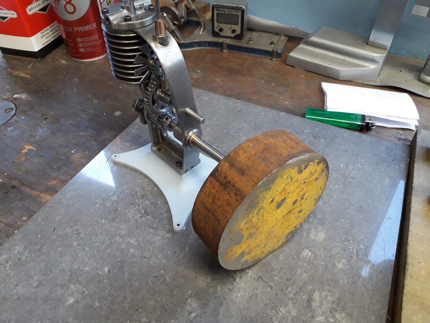
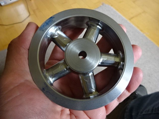
                                              I picked up this piece of 105mm dia EN3 and put it onto the KX3's table briefly stopping at th elathe on the way.

                                              And a little while later pick this up leaving behind a pile of swarf. Not too bad but there are a couple of things I'm not totally happy with so will look into what caused them before doing the next one.

                                              Edited By JasonB on 19/07/2020 17:05:58

                                              #486606
                                              Ron Laden
                                              Participant
                                                @ronladen17547

                                                That is a heavy duty looking wheel Jason, never imagined the Thompson would have such a thick set wheel but then I looked back at the original engine picture and saw it has a real lump of a flywheel.

                                                #486616
                                                JasonB
                                                Moderator
                                                  @jasonb

                                                  I thought a spoked one would look nicer, still got a big hub so the starter cord pulley can be fitted to that. Hopefully will make for some nice slow running. I wanted something that looked a bit like the flywheel on a Wall Wizard

                                                  #486642
                                                  Ron Laden
                                                  Participant
                                                    @ronladen17547

                                                    The Wizard wheel does look good and going by the pictures the spokes look a bit slimmer though it has 6 spokes against your 5. I,m guessing it is something about the spokes you are not happy with, is it possible to put the wheel up again and have enough meat to machine out the problem or is it not that simple or even doable.

                                                    Ron

                                                    #487261
                                                    Roderick Jenkins
                                                    Participant
                                                      @roderickjenkins93242

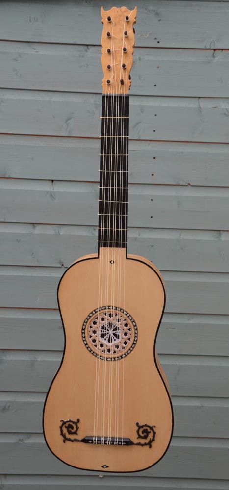
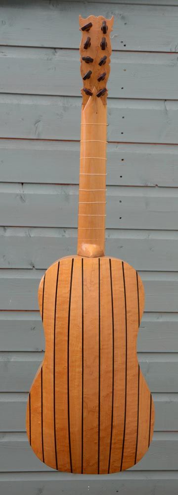
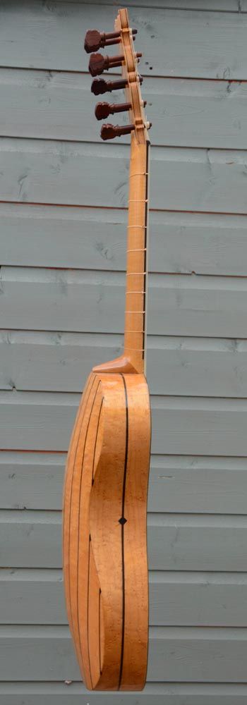
                                                      OK, I know it's only wood but it did come out of my workshop:

                                                      bglr1.jpg

                                                      bglr2.jpg

                                                      bglr3.jpg

                                                      Baroque guitar cobbled together from drawings of a Jacopo Checchucci and an Antonio Stradivari. Birds-eye Maple, Ebony and Alpine Spruce. It's tuned like the top five strings of a modern guitar except the D string is paired with one an octave higher and the A strings are both an octave higher.

                                                      Stay well,

                                                      Rod

                                                    Viewing 25 posts - 176 through 200 (of 284 total)
                                                    • Please log in to reply to this topic. Registering is free and easy using the links on the menu at the top of this page.

                                                    Advert

                                                    Latest Replies

                                                    Viewing 25 topics - 1 through 25 (of 25 total)
                                                    Viewing 25 topics - 1 through 25 (of 25 total)

                                                    View full reply list.

                                                    Advert

                                                    Newsletter Sign-up