The Workshop Progress Thread 2020

Advert

The Workshop Progress Thread 2020

Home Forums Work In Progress and completed items The Workshop Progress Thread 2020

Viewing 25 posts - 251 through 275 (of 284 total)
  • Author
    Posts
  • #498135
    iNf
    Participant
      @inf

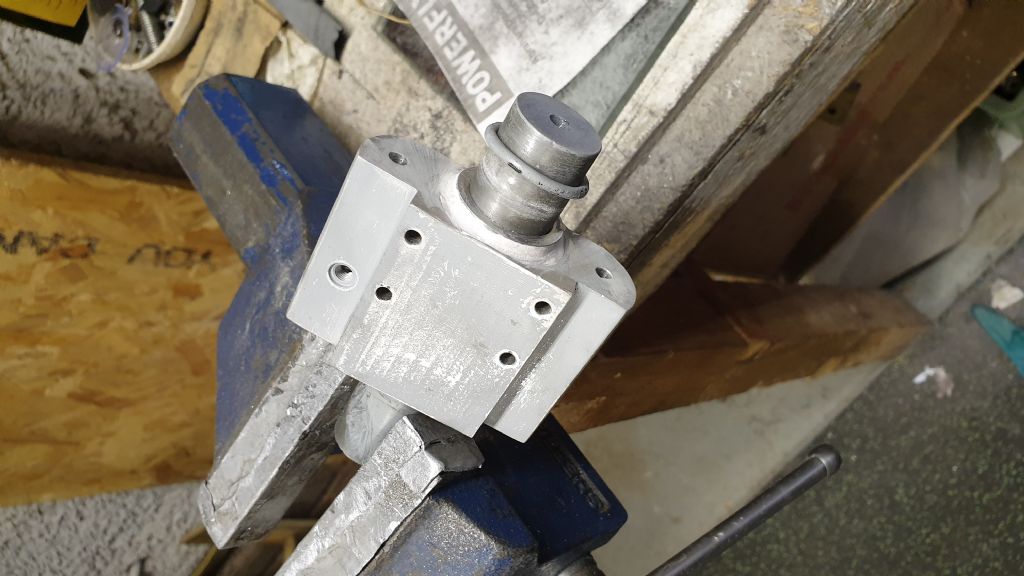
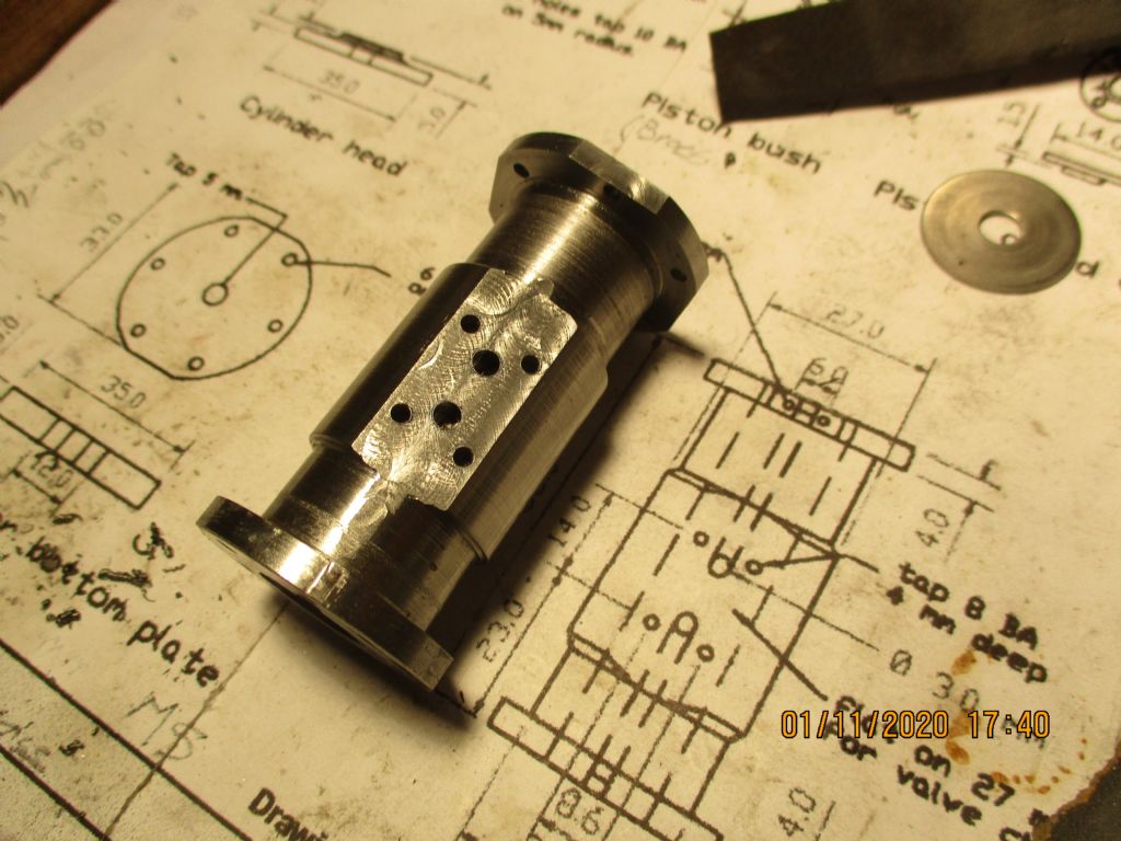
      Having drilled and tapped the various holes in the cylinder, I decided that I wasn't happy with the fillet around the cylinder boss, so out with the filler and a bit of sanding.

      20200822_105540.jpg

      Advert
      #498212
      iNf
      Participant
        @inf

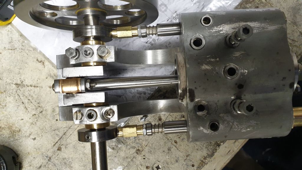
        Having made the crankshaft as per Jason's build thread but before I cut out the middle and pinned it, I did a trial fit with the bearings in the frame only to find it didn't fit! After several 'oh dear me's' I realised I had made the journal 1mm too wide indecision I think that I had been concentrating so hard on getting a good fit in the crank web I had neglected the width. OK I thought, as I had used threadlock to fit it together not having any of the 'proper' stuff , a bit of heat and a gentle tap will soon have it apart….. no chance. Resorting to the hot air gun and bashing with an aluminium mallet so hard the end of the crank resembled a well used cold chisel! After rectifying the problem I realised that I wouldn't need to pin the crank when completed as it wasn't going to come apart anytime soon!

        A picture of the crankshaft during a trial fit/run.

        20200822_172217.jpg

        #498214
        peak4
        Participant
          @peak4

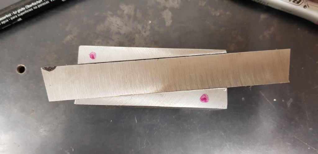
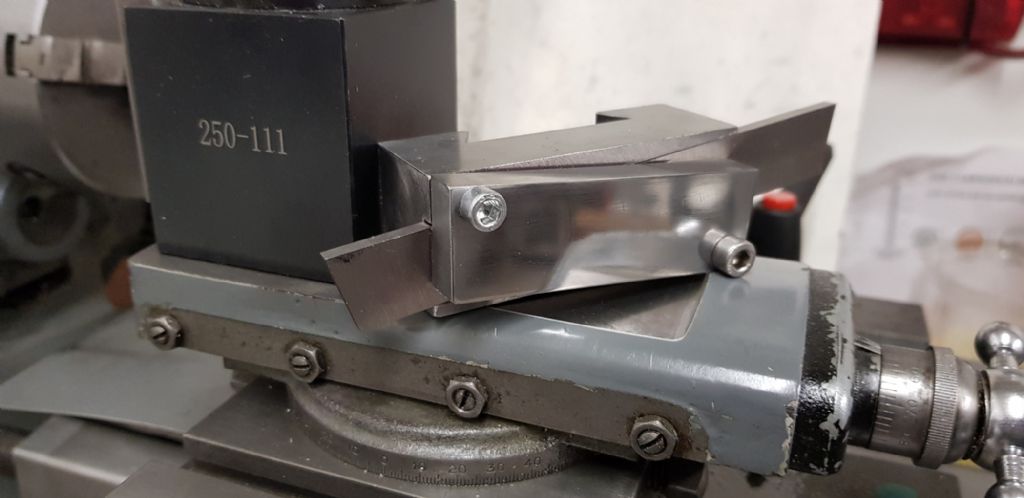
          A few home made 250 size toolholders for the quick release post on my Warco GH1330;

          Quick Change Toolholders
          Four newly completed toolholders to add to my collection for the Big Warco GH1330.
          I used most of the machines in the shop on these; Roughed out on the shaper as one block, with the dovetails finished on the Centec mill. Knurled nuts done on the big Warco and finished on the 720 (Myford clone), Toolholders sawn to length on the Denbigh power hacksaw and finished with a combination of shaper and surface grinder.
          Final finish with gunsmith's blue.
          Not really cost effective to make these, as the originals are about £25 each, but my time's free and it saves getting bored. Also the knurling tool won't fit in the shorter standard toolholder size, such as those three at the front, and as far as I'm aware, you can't buy ones with the through holes to take boring bars.

          Bill

          #498220
          iNf
          Participant
            @inf

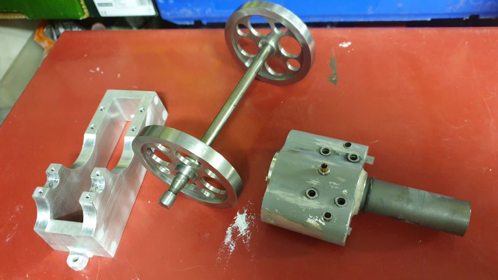
            The main components ready for painting.

            20200823_155901.jpg

            #498243
            iNf
            Participant
              @inf

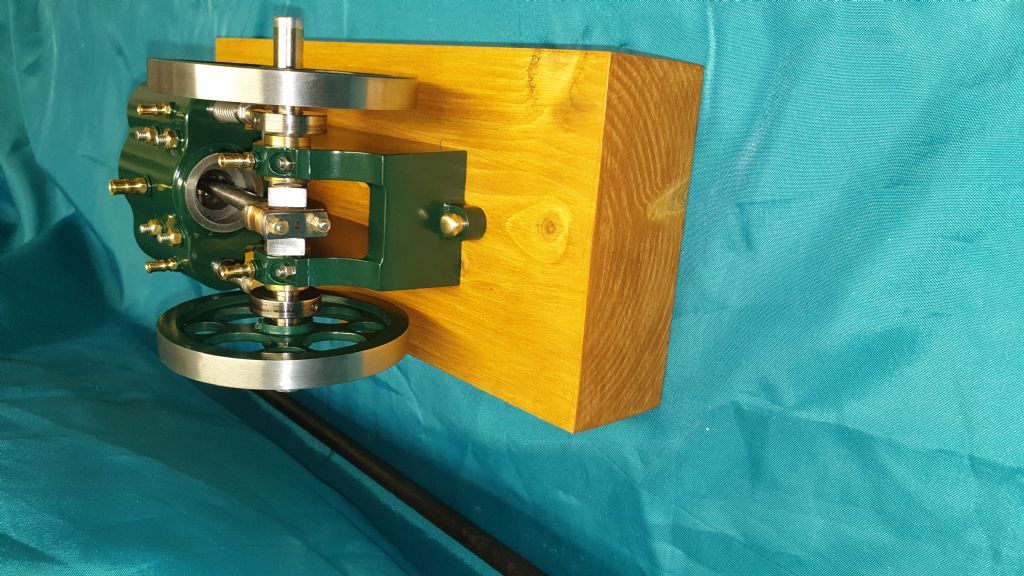
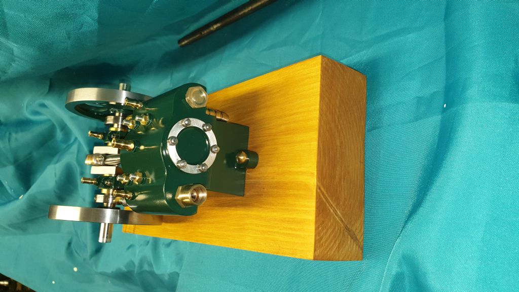
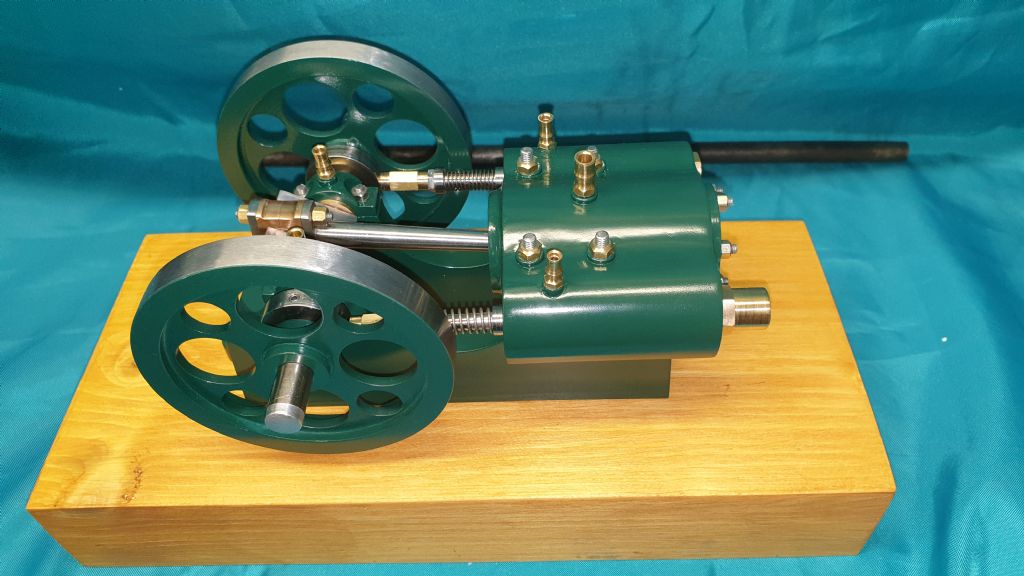
              Finally the finished engine. It's not perfect but I'm quite pleased for a first attempt.

              20200927_195438.jpg

              20200927_195429.jpg

              20200927_195417.jpg

              Hopefully here is a link to the engine running on an old fridge compressor, including some slo/mo

              **LINK**

              #498260
              JasonB
              Moderator
                @jasonb

                That turned out very nicely and runs well too.

                #498293
                Jim Nic
                Participant
                  @jimnic

                  Congratulations. Another fine example of Jason's Jowitt and with a result as good as that on your first "real engine" perhaps an encouragement to others to give it a go.

                  Jim

                  #498337
                  Oldiron
                  Participant
                    @oldiron
                    Posted by peak4 on 27/09/2020 21:19:45:

                    A few home made 250 size toolholders for the quick release post on my Warco GH1330;

                    Quick Change Toolholders
                    Four newly completed toolholders to add to my col

                    lection for the Big Warco GH133. Also the knurling tool won't fit in the shorter standard toolholder size, such as those three at the front, and as far as I'm aware, you can't buy ones with the through holes to take boring bars.

                    Bill

                    Nice job Bill. I have made 9 of these 250 style holders for myself. I made 5 of mine so they will take 20mm tools. Instead of the std 12mm lip at the bottom I made it 7mm. Never had a problem with the smaller dimension.

                    The boring bar holder is 250-204. It has a 25mm ID hole and a 25 OD x 19mm ID split sleeve for smaller bars. I also made split sleeves for 16 & 12mm bars.

                    regards

                    #498359
                    iNf
                    Participant
                      @inf

                      Thanks for the comments Jason and Jim. I probably wouldn't have attempted it without Jason's build thread to guide me. I certainly learned a few things along the way. I have no idea how Jason can produce such stunning engines so quickly!

                      Thanks

                      Dave

                      #498374
                      Steviegtr
                      Participant
                        @steviegtr

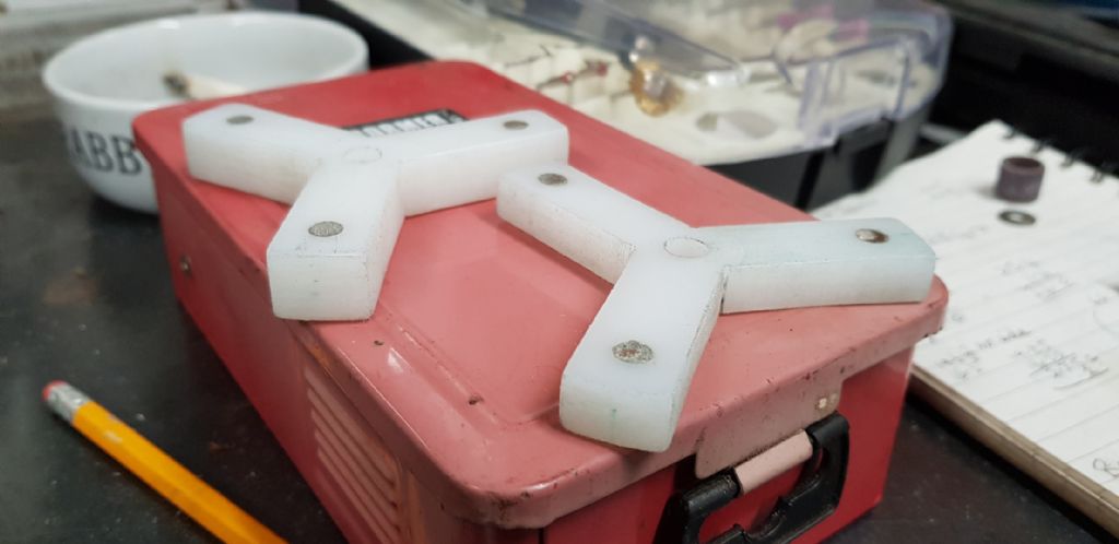
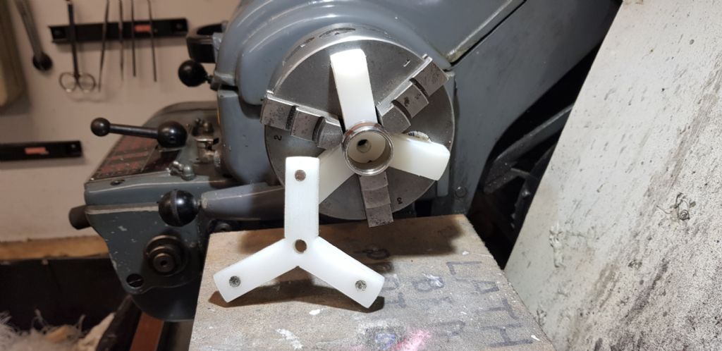
                        Made 2 chuck spacers to help with ring making. Little magnets attached.

                        Steve.

                        chuck spacers 1.jpg

                        chuck spacers 2.jpg

                        #498376
                        peak4
                        Participant
                          @peak4
                          Posted by Oldiron on 28/09/2020 18:21:53:

                          Nice job Bill. I have made 9 of these 250 style holders for myself. I made 5 of mine so they will take 20mm tools. Instead of the std 12mm lip at the bottom I made it 7mm. Never had a problem with the smaller dimension.

                          The boring bar holder is 250-204. It has a 25mm ID hole and a 25 OD x 19mm ID split sleeve for smaller bars. I also made split sleeves for 16 & 12mm bars.

                          regards

                          Cheers, The original incentive was the knurling tool holder, as I was using an extended nose one I'd made previously.
                          The Boxford shaper has an 8" stroke, so it wasn't much harder to make four, adding up to a 7½" block.
                          In my case, I do have a 202 holder with the groove in the bottom housing a larger boring bar; these two are 7 & 12mm.
                          I don't have any other larger tooling, so these will suffice for the time being, unless I add a couple of dedicated parting tool holders.

                          Bill

                          #498385
                          Steviegtr
                          Participant
                            @steviegtr
                            Posted by peak4 on 28/09/2020 21:12:43:

                            Posted by Oldiron on 28/09/2020 18:21:53:

                            Nice job Bill. I have made 9 of these 250 style holders for myself. I made 5 of mine so they will take 20mm tools. Instead of the std 12mm lip at the bottom I made it 7mm. Never had a problem with the smaller dimension.

                            The boring bar holder is 250-204. It has a 25mm ID hole and a 25 OD x 19mm ID split sleeve for smaller bars. I also made split sleeves for 16 & 12mm bars.

                            regards

                            Cheers, The original incentive was the knurling tool holder, as I was using an extended nose one I'd made previously.
                            The Boxford shaper has an 8" stroke, so it wasn't much harder to make four, adding up to a 7½" block.
                            In my case, I do have a 202 holder with the groove in the bottom housing a larger boring bar; these two are 7 & 12mm.
                            I don't have any other larger tooling, so these will suffice for the time being, unless I add a couple of dedicated parting tool holders.

                            Bill

                            I also made some of those a while ago. I have parting tool as seen below. This was part way through making it.

                            eclipse 2.jpg&

                            & nearly finished item.

                            parting off 1.jpg

                            Final item

                            parting tool finished.jpg

                            Steve.

                            Edited By Steviegtr on 28/09/2020 21:39:31

                            Edited By Steviegtr on 28/09/2020 21:46:49

                            #498953
                            Anthony Knights
                            Participant
                              @anthonyknights16741

                              I have made a start on the "Grasshopper" engine by Stewart Hart after he kindly emailed me the plans. So far I have completed the horizontal beam assembly.beam assy.jpg

                              #499645
                              JasonB
                              Moderator
                                @jasonb

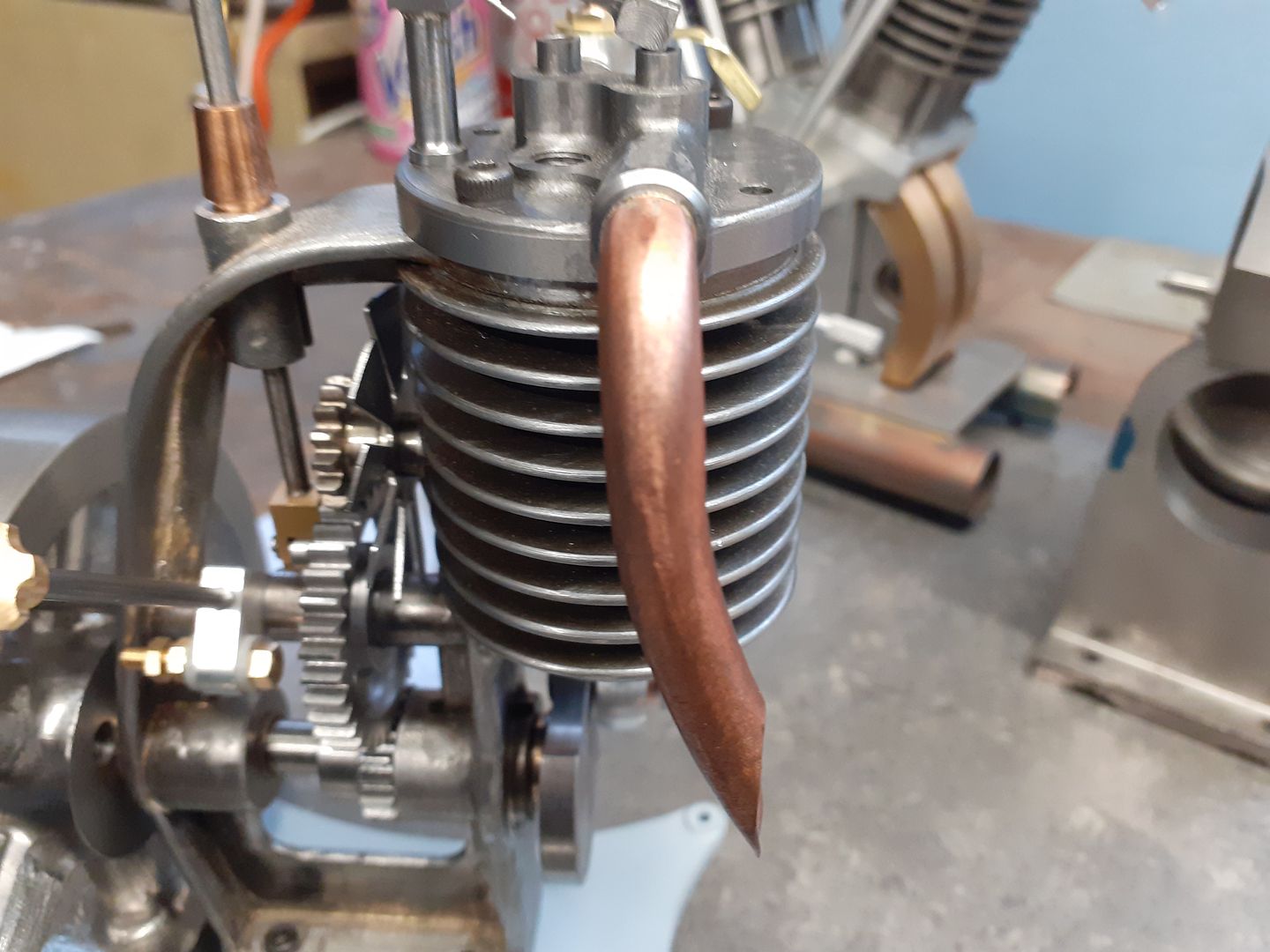
                                The weekend saw a few more bits done for my Thompson engine, firstly the exhaust was bent up from 8mm copper tube, soldered to a threaded spigot and locking collar turned

                                Then then all the parts for the carb were made up, similar design to the one I made for the Midget engine with a few alterations

                                All was done by flitting back and forth between the lathe and manual mill with the exception of the throttle leaver which was less than a two minute job for the CNC to cut and no sign of any difference running it with the revised Free F360.

                                #504564
                                JasonB
                                Moderator
                                  @jasonb

                                  After a brief interlude for some top secret pattern making the CNC was dusted down so I could get back to making metal swarf. Starting from the bottom this is the first part of a new engine based ob the 36cc Wall 2-stroke but scaled down from it's original 1.5" bore to 24mm it will be approx 11cc.

                                  Part is 60mm long 6082 Aluminium, Adaptive cleared, ramp to shape, horizontal to tops of lugs, spot and then two different drill operations. The slight visible line between the tops of the two lugs is just a change in cutter direction where it did a cut all round at 12mm leaving a horizontal witness mark, all the others are at a slight slope being cut on a 0.33mm ramp. ( cutter goes all the way around with a constant downwards travel to bring it 0.33mm lower each loop.)

                                  #504632
                                  DiogenesII
                                  Participant
                                    @diogenesii

                                    Always nice to see progress on the Thompson, I think it's a fascinating design – still can't work out whether it's the work of a genius or of the Devil, though..

                                    And what's that carelessly-placed narrow-angle "V" on the bench behind?

                                    #504641
                                    JasonB
                                    Moderator
                                      @jasonb

                                      Thanks, Thompson has been running but is stripped down for tarting up and painting.

                                      That's my Hoglet that I built in about 2010 and never quite finished, but have been doing the last few items on that recently.

                                      #504759
                                      DiogenesII
                                      Participant
                                        @diogenesii

                                        Looking forward to seeing the finger mincer run – and progress on the Hoglet.. it's good to see some engines, thanks for posting

                                        #504784
                                        David Caunt
                                        Participant
                                          @davidcaunt67674

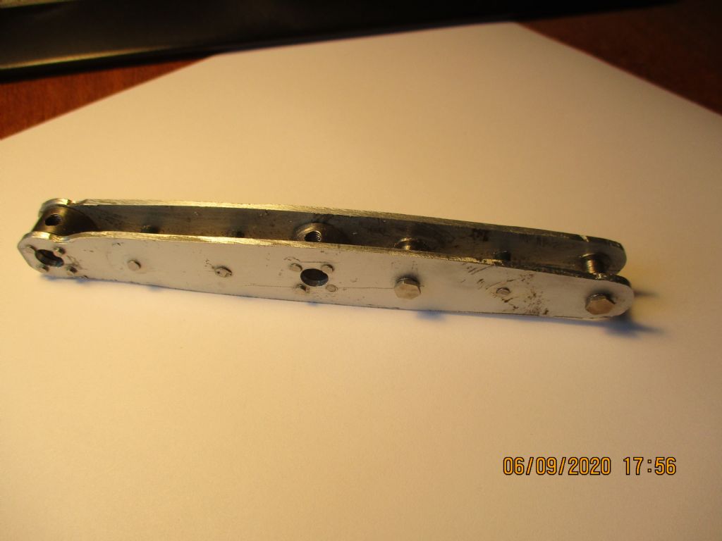
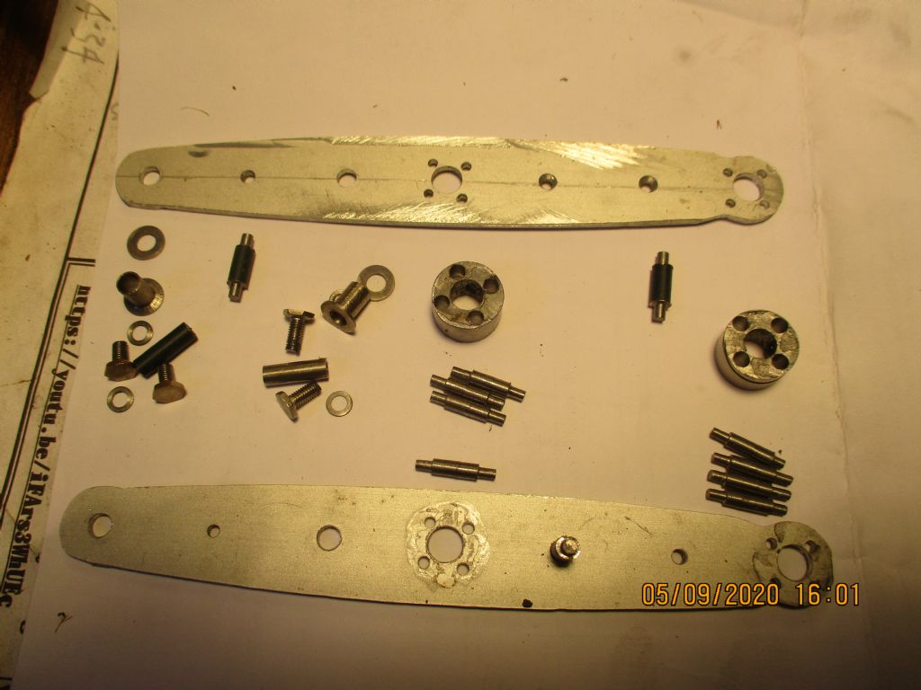
                                          cylinder and valve block_0803.jpghalf beam assembled_0779.jpgSeeing Anthony's Grasshopper Beam made me wish I'd chosen something simpler. This beam is a bit more complicated but when all the rivets lined up it was quite a gratifying moment. all the bits for the beam_0772.jpg

                                          This was in May at 2 hours on most days it takes a long while to get anywhere. Here is the cylinder and part finished poppet valve block.

                                          cylinder and valve block_0802.jpg

                                          #504785
                                          David Caunt
                                          Participant
                                            @davidcaunt67674

                                            Sorry Pics and writing seems to be all over the place and it was started in September. DOH!!

                                            #505968
                                            John Hinkley
                                            Participant
                                              @johnhinkley26699

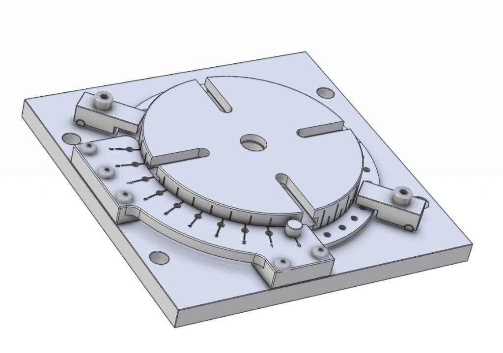
                                              Spurred on by lockdown Mk2 and interest from steveiegtr on the "What did you do today" thread, amonst no others, I decided to go ahead with the construction of the low-profile rotary table. I have further refined and simplified the design and incorporated a few improvements and it now looks like this:

                                              Rotary table Alibre Atom file

                                              I also thought that I'd add a series of short videos to my YouTube channel to document the build and help pass the time. Suffice to say, I won't be planning a trip to the Oscars next year! If you want a laugh at my expense, have a look at this:

                                              Low profile rotary table

                                              Parts 2 and 3 are in production and will appear in due course.

                                              John

                                              #509040
                                              John Hinkley
                                              Participant
                                                @johnhinkley26699

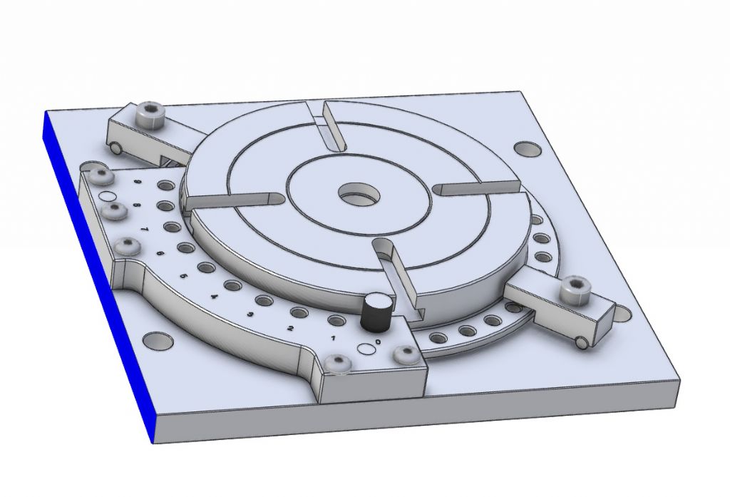
                                                Spent a goodly part of the day carving the vernier plate out on the mill. Lots of vibrations, so I didn't bother to video it all, just took a few stills and left the video to the "sweep-up" bit at the end. In the light of the experience, I amended the Atom drawings to reflect the final, final, version to reflect the changes I've made to make it easier to produce.

                                                GA final iteration

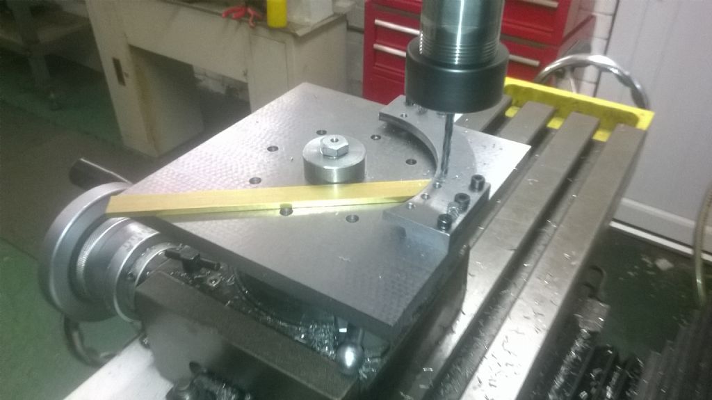
                                                This is the vernier plate with the major machining completed and the vernier holes being drilled:

                                                Drilling vernier holes

                                                It's a little blurred as its grabbed from the video.

                                                Still got to clean up the edges and then make the minor parts to finish the project.

                                                John

                                                #509817
                                                Anthony Knights
                                                Participant
                                                  @anthonyknights16741

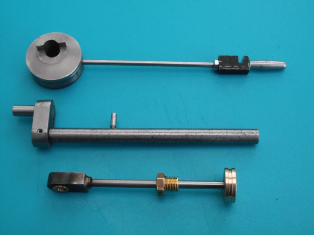
                                                  Since my last post, I have made some more bits for the Stewart Hart "Grasshopper" engine.

                                                  assemblies.jpg

                                                  These are – Eccentric assembly, Main axel and crank, Piston rod assembly.

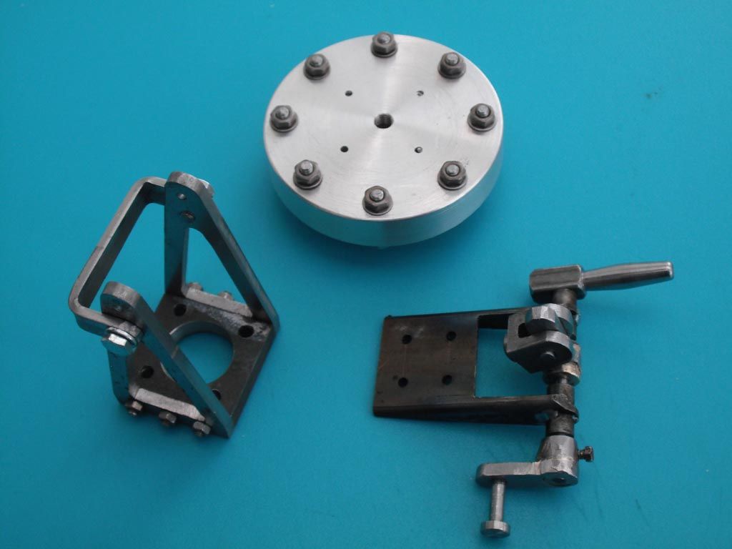
                                                  I have also done some of the "fiddely bits" which seem to have taken forever.

                                                  fiddley_bits.jpg

                                                  These are – Cylinder base, The "A" frame assembly, The valve linkage assembly.

                                                  They all need "fettlling" to tidy them up a bit, but I don't want to make them too perfect as the original machine was probably made mainly from castings. The cylinder base is made from aluminium and is a bit too shiny for me, so I'll have to treat it some way (paint?) to tone it down.

                                                  Next job is the cylinder and the end caps.

                                                  #510434
                                                  John Hinkley
                                                  Participant
                                                    @johnhinkley26699

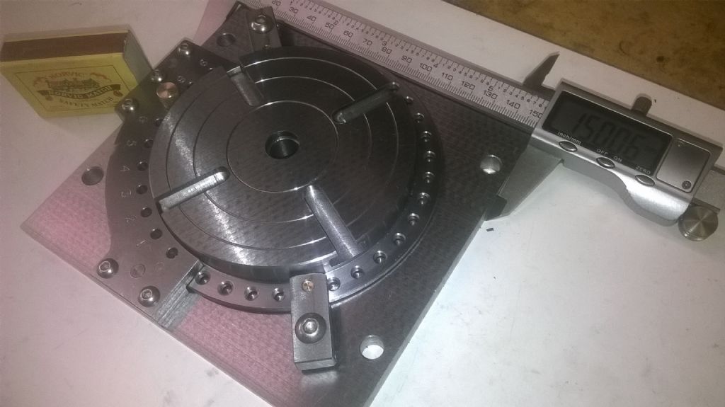
                                                    Today, I completed the build of my low-profile rotary table with 1° vernier indexing plate. It's taken a lot longer than I thought, due mainly to producing videos of the build at the same time (and having to learn how to use the video editor). Here's the finished article:

                                                    Finished!

                                                    The caliper reads 150mm, difficult to read in this photograph. The matchbox is not part of the design,just placed there for an idea of scale. The overall height is 26mm.

                                                    You can see the whole series on my YouTube channel HERE , should you so wish. Be warned, however, it's a long series, but you can always skip the boring (and turning) bits.

                                                    John

                                                    #510451
                                                    Steviegtr
                                                    Participant
                                                      @steviegtr
                                                      Posted by John Hinkley on 28/11/2020 15:41:15:

                                                      Today, I completed the build of my low-profile rotary table with 1° vernier indexing plate. It's taken a lot longer than I thought, due mainly to producing videos of the build at the same time (and having to learn how to use the video editor). Here's the finished article:

                                                      Finished!

                                                      The caliper reads 150mm, difficult to read in this photograph. The matchbox is not part of the design,just placed there for an idea of scale. The overall height is 26mm.

                                                      You can see the whole series on my YouTube channel HERE , should you so wish. Be warned, however, it's a long series, but you can always skip the boring (and turning) bits.

                                                      John

                                                      Very nice. Now on to look at your video.

                                                      Steve.

                                                    Viewing 25 posts - 251 through 275 (of 284 total)
                                                    • Please log in to reply to this topic. Registering is free and easy using the links on the menu at the top of this page.

                                                    Advert

                                                    Latest Replies

                                                    Viewing 25 topics - 1 through 25 (of 25 total)
                                                    Viewing 25 topics - 1 through 25 (of 25 total)

                                                    View full reply list.

                                                    Advert

                                                    Newsletter Sign-up