The Workshop Progress Thread 2019

Advert

The Workshop Progress Thread 2019

Home Forums Work In Progress and completed items The Workshop Progress Thread 2019

Viewing 25 posts - 51 through 75 (of 261 total)
  • Author
    Posts
  • #394416
    JasonB
    Moderator
      @jasonb

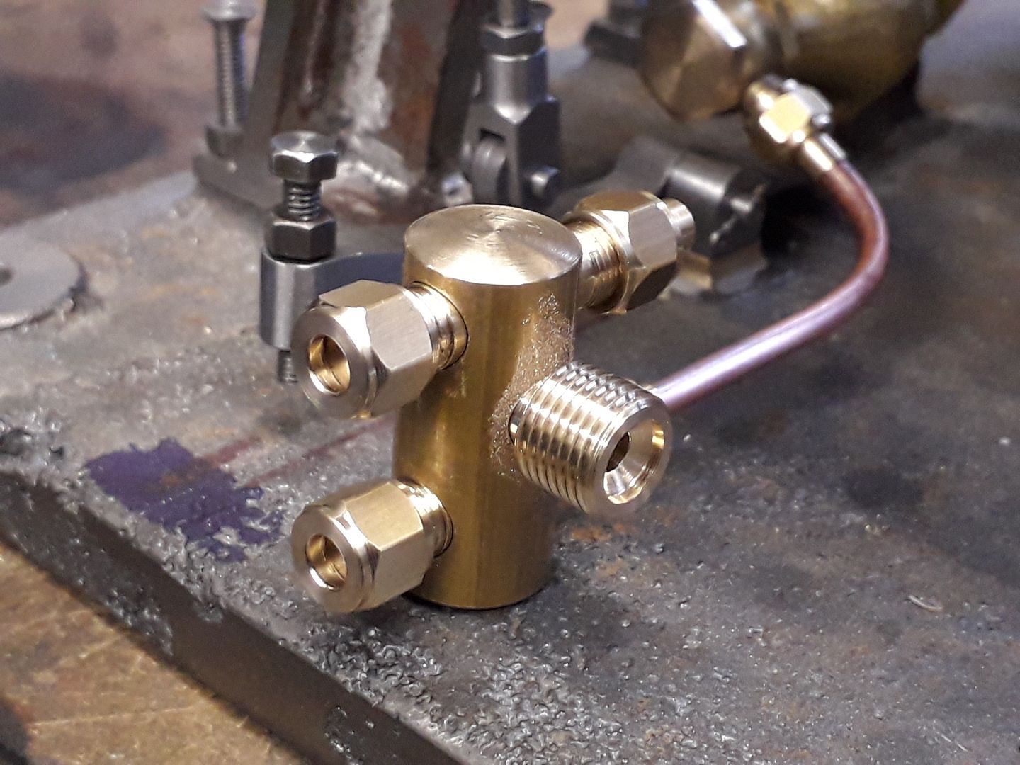
      Carrying on with the plumbing for the Allman I have been working on a twin needle valve assembly to hopefully control the gas better than the commercial valve I used for the Robinson.

      In the photo below gas will enter via the 1/8" BSP thread half way up then go down to the engine feed (already puimbed in copper)and up to the burner. The two nuts on teh left will be the gland nuts for the needles and will be operated by small [s]hand[/s] finger wheels.

      Just finished cutting an M10 x 0.75 thread to make an adaptor that will replace the stainless steel end of the smallest Sievert burner so I can screw into a 1/8" BSP elbow. You can just see what goes inside it top right.

      Advert
      #394422
      Andy Carruthers
      Participant
        @andycarruthers33275

        Hats off to you all!

        Far beyond my capability – I did manage to make a dovetail tool holder for my QCTP without breaking anything though, which is an schievement in itself

        #394468
        JasonB
        Moderator
          @jasonb

          The modified Sievert burner seems to be working OK now that I have also reduced the incomming air by pressing on a sleeve with just two 0.75mm holes.

          #394706
          mechman48
          Participant
            @mechman48

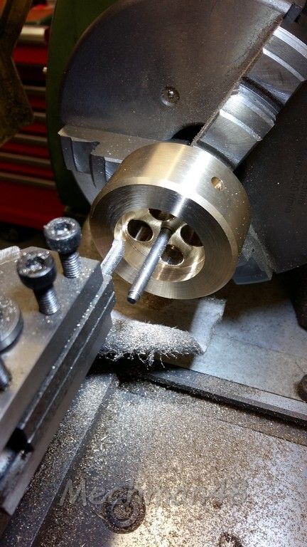
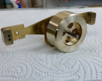
            A bit more progress on my Boxer twin oscillator, been on the back burner for a while…. discarded the first flywheel as it was too big in OD & ID ( from another project ), made a new one…

            flywheel.remade.jpg

            so far…

            32.osc.flywheel update.jpg

            George.

            #394749
            Ron Laden
            Participant
              @ronladen17547
              Posted by JasonB on 03/02/2019 10:39:57:

              The modified Sievert burner seems to be working OK now that I have also reduced the incomming air by pressing on a sleeve with just two 0.75mm holes.

              The burner does look to be working well in the way the flame pattern heats up the top 2/3rds of the hot tube. From an earlier picture the burner assy looks to be housed in a vertical housing next to the cylinder, I guess there must be some kind of inlet valve arrangement at the top of the tube. Also is the purpose of the hot tube to maintain a constant level of heat rather than just having a burner. Interesting how some of these engines work.

              #394755
              Ian S C
              Participant
                @iansc

                Jason, Is there some obstruction in the burner design that prevents a complete ring of burner holes? Not important as the burner seems to be doing its job well, how does it go in the chimney.

                Ian S C

                #394759
                JasonB
                Moderator
                  @jasonb

                  Ron, I'll section a few part sin Alibre and explain how the hot tube goes together later.

                  Ian, yes the ring of fire does not go all the way round as I left a section solid to take a grub screw so the position of the ring can be adjusted, altering the height will advance or retard the ignition. Chimney will be just above the top of the ring.

                  #395671
                  JasonB
                  Moderator
                    @jasonb

                    just fancied some simple turning this weekend so got a few bits and pieces done for what I likely to be the next engine, as an idea of size the long rod at the top is 1/8" dia.

                    Also did the flywheel, by the smell of it and the curly swarf it would seem to be SG Iron.

                    #395793
                    Ron Laden
                    Participant
                      @ronladen17547

                      Steady on Jason, I cant keep up, you have two different engines well under way and your now making parts for a third (you will probably say there is another in the pipeline also).

                      Your work rate and progress is something else, I dont know how you cope with it but it certainly is impressive to say the least..smiley

                      Ron

                      #395805
                      Howard Lewis
                      Participant
                        @howardlewis46836

                        Have just (successfully, I hope) completed a mechanical jigsaw. It was a Cobbler automaton. Unfortunately, at some time it had been subjected to great forces, and then half repaired.

                        Before coming to me the ruined motor and integral gearbox had been replaced, but nothing had been done about the bent actuating rods, and a foul between the over long screw that retained the cam follower to the transverse lever. (Presumably part of the "repair" ).

                        The frame and the lever were slightly distorted, as was the cam (which seemed to been fitted the wrong way round. (Grubscrews inside and almost inaccessible), resulting in the follower being packed out to mesh with the follower with a number of washers.

                        At least, after clocking on an arbor and a combination of levering and impacts got it true within 0.008" Then turned up a new spacer so that the cam engaged the follower.

                        Not knowing what should be present, or how everything should be arranged resulted in a lit of village blacksmithing, followed by a lot of trial and error.

                        Two adjustable rods with ball joints (received bent, but straightened) could each be fitted in two holes, and inboard or outboard. When assembled, and with the rods adjusted, as i thought correctly, it worked until the back was fitted! Moving the outer ball jointed rod inboard decreased the foul, but did not eliminate it completely, so the plastic back had to be carved away, locally.

                        A slight rerouting of the wires away from the moving parts and it now works, more or less as I would expect.

                        So hopefully, when collected, I shall receive a donation for my M E Club, and we shall all be satisfied.

                        Howard  Expletive and Emoji deleted!

                        Edited By Howard Lewis on 11/02/2019 14:34:54

                        #395844
                        duncan webster 1
                        Participant
                          @duncanwebster1

                          A bit of progress on motion plates, how can it take so long to drill and tap 12 holes? Not the easiest thing to hold together with the bits in the right place I supposemotion brackets assembled (small).jpg 

                          Edited By duncan webster on 11/02/2019 20:10:09

                          #395846
                          Pete White
                          Participant
                            @petewhite15172

                            Engineering porn, smileygreat photos, keep up the good work and posts, much appreciated.

                            Pete

                            #395919
                            mechman48
                            Participant
                              @mechman48

                              Howard; a couple of pics of the cobbler automaton would be nice.

                              George.

                              #396194
                              Howard Lewis
                              Participant
                                @howardlewis46836

                                Sadly, was so obsessed with sorting it out that took no pictures. Should have, if only to show the damage and bodges, (likely to make matters worse ), previously present.

                                Would guess, from the telephone number on the baseboard, that it was pretty old (020 code)

                                Basically, a geared shaded pole motor drove a multilobe cam. The follower is on a lever which pivots on the left frame. The lever carries three screwed rods, with ball joint ends, which run vertically upwards. The undamaged one nods the head, the two that needed straightening and adjusting operate the right arm, wielding the hammer, and the outer one, a bell crank which drives a horizontal rod at shoulder level, which causes the left hand to sweep to and fro across the shoe on the "anvil".

                                The fact that the two rods had been bent in compression implied some fairly large forces, (hence the original motor ran, but did not drive the output shaft ).

                                The cam had been fitted inside out, making the grubscrews inaccessible, which explained why it was loose on the shaft! When fitted with the hub outwards, the cam was running out. It was secured to an arbor, in the lathe and checked with a DTI. The DTi was moved away to allow gentle persuasion, or levering, at appropriate points, until it ran reasonably true again, (1mm+ reduced to less than 0.2mm ) At least the cam now stayed in the groove in the ball bearing follower. Having dispensed with the pack of washers, a solid spacer was turned up to align the follower with the cam.

                                Adjusting the rods took time, because to make any adjustment meant removing a ball joint, giving it one turn and refitting, before checking the effect of the adjustment.

                                Once operating satisfactorily, the back was fitted; which promptly stalled the motor! The ball joint on the outer rod fouled. The rod was refitted with the ball joints inboard, but a foul still remained. This was cleared by drilliing a hole in the plastic back, and steadily carving bits away, to extend it, until the foul cleared.

                                From its state, the shirt was even older than the ones that i wear in the workshop; and that's saying something!

                                The new owners seemed impressed with my description of the "as received" condition, the repairs,and the "after" operation, that they gave a bigger donation to Club funds than I had expected.

                                So everyone was happy!

                                Howard

                                #401545
                                duncan webster 1
                                Participant
                                  @duncanwebster1

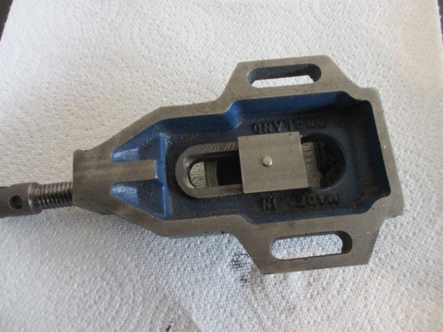
                                  Not my idea, Mr Tredenick from Australia, as featured in MEW Feb 19. How to stop the jaw lifting on your Record drilling vice. Only took an hour or so

                                  img_3538 (small).jpg

                                  img_3539 (small).jpg

                                  Edited By duncan webster on 21/03/2019 15:50:36

                                  #403441
                                  Jim Nic
                                  Participant
                                    @jimnic

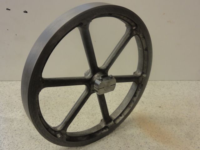
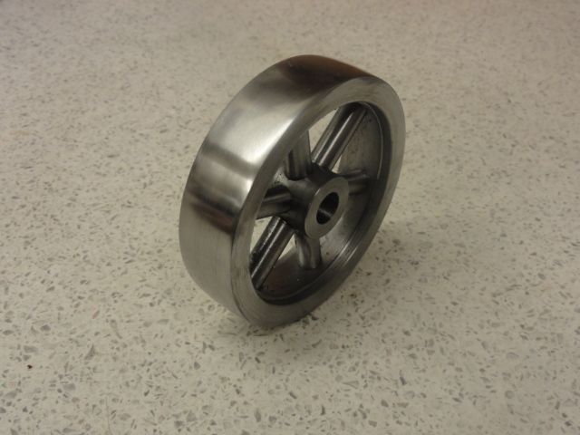
                                    In my last post on the progress of Stew Hart's Overcrank design I had made the valve eccentrics (and the eccentric straps) which had to be fitted to the crankshaft centre section before assembling the shaft. I then thought that making up the shaft would naturally be the next operation. When I came to cut the 12mm dia bar to length for the main part I found that the exact length depended on the width of the flywheel and the output pulley hubs. Sooo the next task was to obtain a flywheel casting from Stuart Models and machine it and make a pulley and, while I was at it, a pulley for the governer belt.

                                    flywheel 6.jpg

                                    output 16.jpg

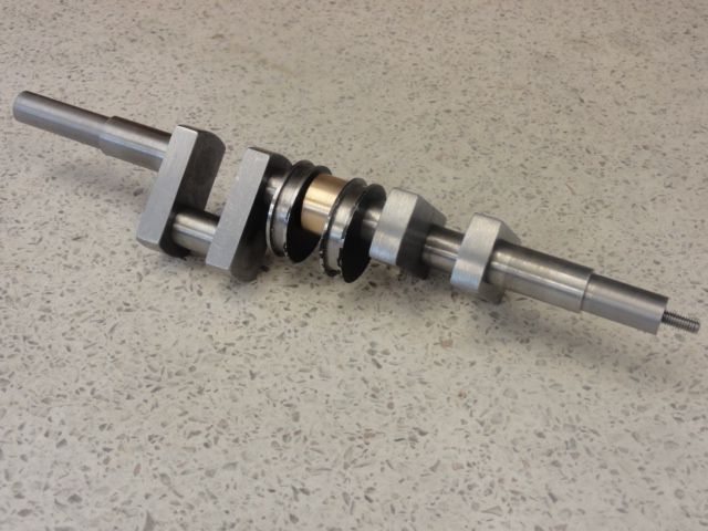
                                    Then I assembled the crankshaft using my usual Loctite method but since this was a twin cylinder engine I also pinned the webs. The pins are fitted through the webs from one end, go through both the "big end" and the shaft section but stop short of protruding from the other end of the web.

                                    crankshaft 6.jpg

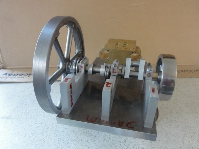
                                    And here is an assembly shot of the crankshaft in position before I had cut out the redundant pieces between the webs.

                                    crankshaft 7.jpg

                                    Next up I get to fit the laser cut crank return rods

                                    return conn rods.jpg

                                    Jim

                                    #406020
                                    JasonB
                                    Moderator
                                      @jasonb

                                      had a try at getting the I F Allman engine going over the weekend and it's nearly there. A few fine tweaks to the gas flow to the actual engine and the position of the burner to get the timing spot on should have it firing a bit more often which should result in some longer runs.

                                      #406037
                                      Ian Skeldon 2
                                      Participant
                                        @ianskeldon2

                                        Duncan Thanks for the tip, will give that a go.

                                        Jason I love that engine, just to give an idea of the size, what diameter is the fly wheel?

                                        #406039
                                        JasonB
                                        Moderator
                                          @jasonb

                                          10.5" dia and very heavy due to the thick section rim.

                                          #406075
                                          Ian Skeldon 2
                                          Participant
                                            @ianskeldon2

                                            But what a beauty she is, nice one Jason.

                                            #406160
                                            duncan webster 1
                                            Participant
                                              @duncanwebster1

                                              Getting ready for a repetition job, thought a rear toolpost for my little lathe might help, so here it is, not quite finished, needs another tee nut making to hold it down, but grand dad duties call.rear toolpost (small).jpg

                                              #407139
                                              john carruthers
                                              Participant
                                                @johncarruthers46255

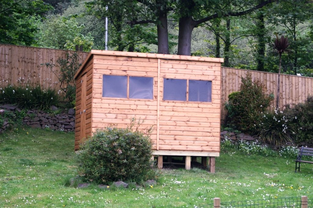
                                                The new shed/workshop is finally erected, I've been aiming for a better set up since we got here last October.
                                                8' x 10' from ShedsAhead of Port Talbot who did the installation.
                                                Because of the slope and underlying limestone it sits on 18 4"x4" piles.

                                                Next the power and light, then the benches. I've been saving the old kitchen units and worktops for this job.

                                                new shed - copy.jpg

                                                #407819
                                                JasonB
                                                Moderator
                                                  @jasonb

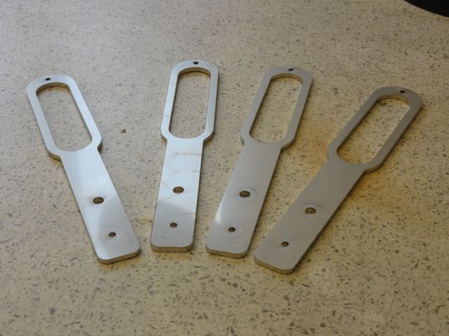
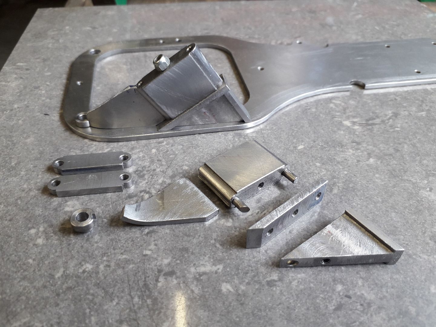
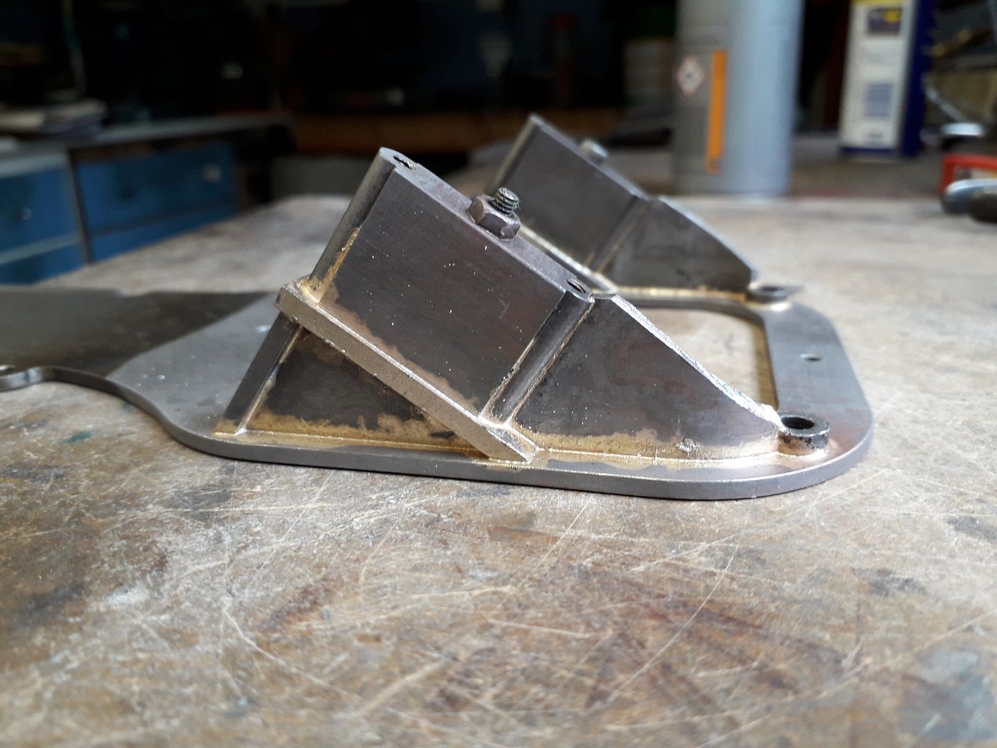
                                                  I've been machining up a few more bits for the mill engine I posted in the KX-3 thread that will make up the bearing housings.

                                                  Then heated them up with a bit of flux and silver solder thrown in for good measure

                                                  And after a 40 min soak in brick cleaner the solder looks to have flowed OK. Just need to file the two curved webs to shape now.

                                                  #408096
                                                  Roderick Jenkins
                                                  Participant
                                                    @roderickjenkins93242

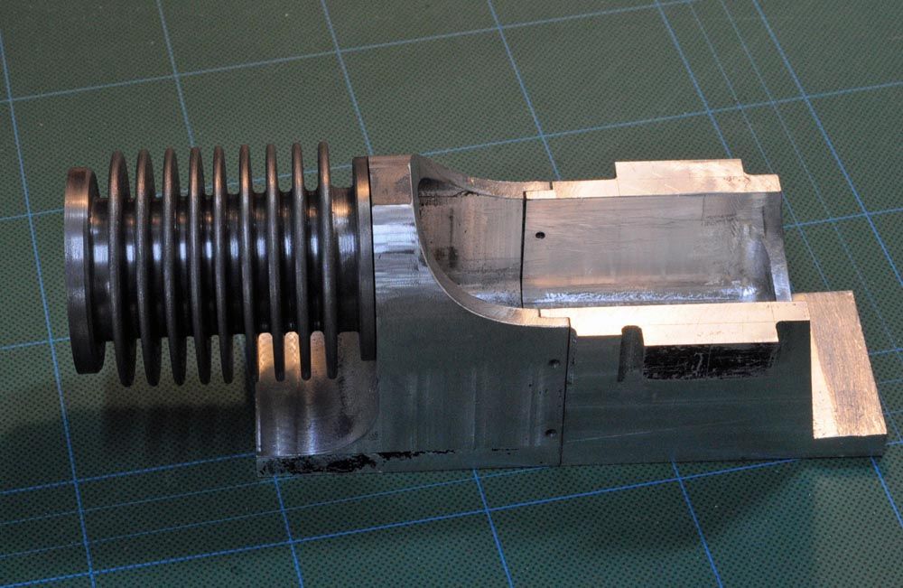
                                                    Machined the cylinder for my (air-cooled) Farm Boy hit n miss

                                                    fbq.jpg

                                                    Rod

                                                    #408100
                                                    JasonB
                                                    Moderator
                                                      @jasonb

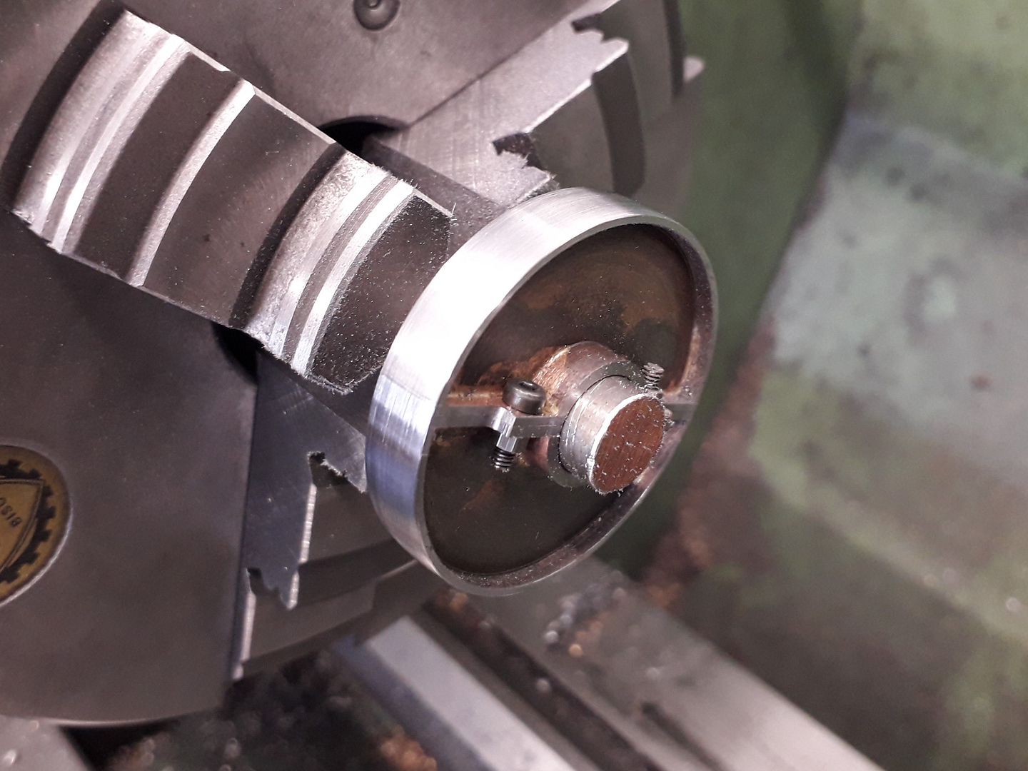
                                                      Yesterday i made a split pulley to drive the mill engine's governor, was happy that it held on the 10mm PGMS shaft for final turning and crowning of the face. 40mm OD and M2 temporary fixings, just a bit of filing to round off the flange around the bolts to do.

                                                    Viewing 25 posts - 51 through 75 (of 261 total)
                                                    • Please log in to reply to this topic. Registering is free and easy using the links on the menu at the top of this page.

                                                    Advert

                                                    Latest Replies

                                                    Viewing 25 topics - 1 through 25 (of 25 total)
                                                    Viewing 25 topics - 1 through 25 (of 25 total)

                                                    View full reply list.

                                                    Advert

                                                    Newsletter Sign-up