Finally got to do the Rotary Encoder for my EMCO V10 X Axis.
I have an old – 20 years – FAGOR DRO control unit with one working glass scale that I used on the V10 Z Axis, mounted behind the bed. The glass scale that used to be used on the X axis was smashed, and that's how I came to 'owning' this FAGOR unit – saved from the trash…
I decided to try and make a rotary encoder fitted into the handwheel area of the cross slide, and adapting that encoder output to drive the FAGOR Unit.
The encoder is a 1024 pulse/rev Quadrature encoder ( 2 pulse trains, one 90deg phase lagging the other). This gives in effect 4×1024 – 4096 edges per revolution. My leadscrews is a 2mm pitch, and the FAGOR unit glass scale gave 400 pulse per rev of the handwheel, ie, 400 pulse for 2mm movement ( 0.005mm resolution). So I used an Arduinio and some software to basically interpolate ( via Bresenhams, for those interested) the 4096 edges down to 400, and made the FAGOR display very happy..The whole thing is together, and works very nicely – Of course it does not measure axis movement, but leadscrew rotation, so does not take care of backlash, but on the cross slide, one tends to work in one direction anyway, even when using the handwheel dials..
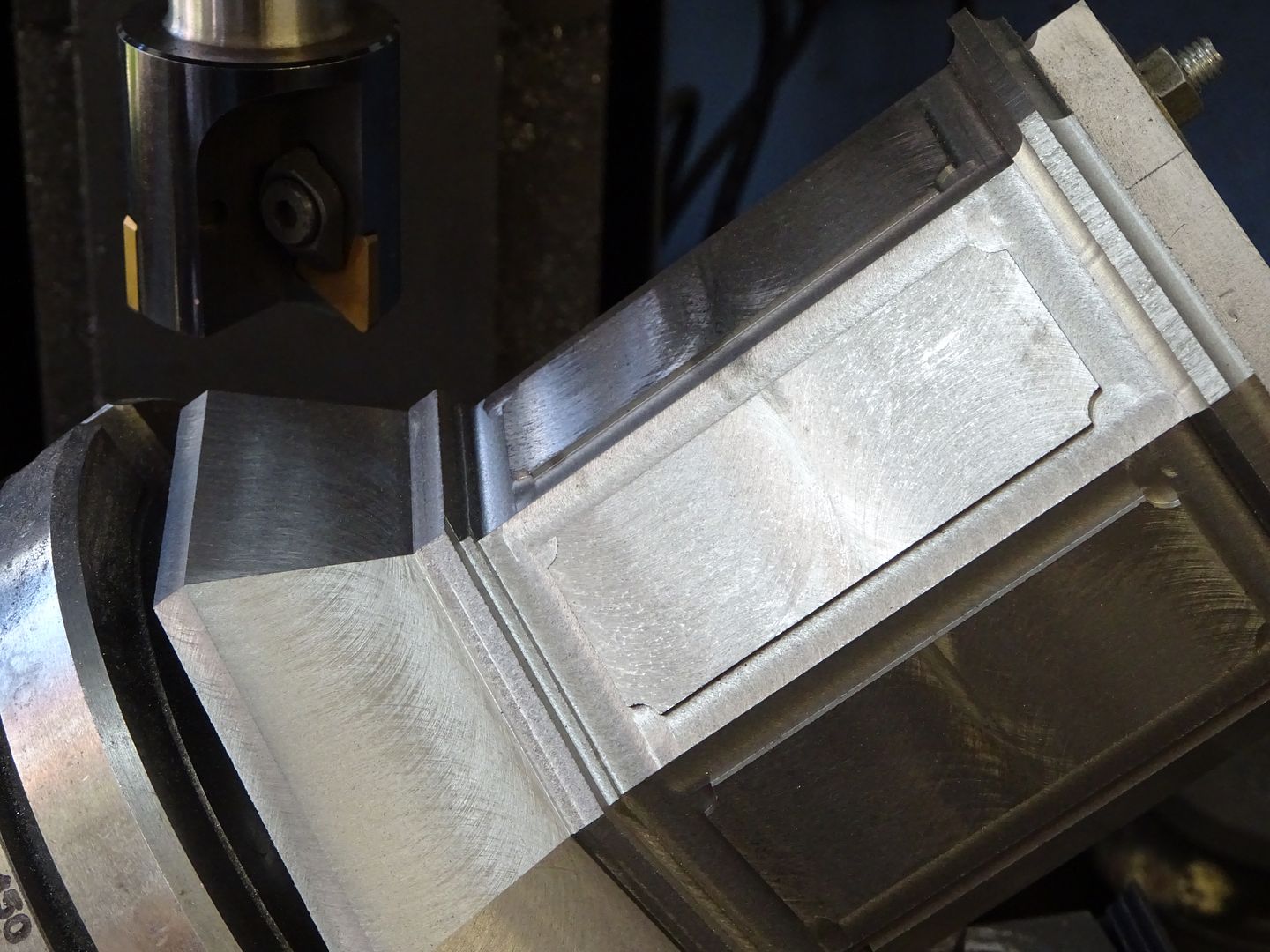
milling the encoder housing to shape:

The front cover plate – yucky stringy aluminium alloy this..

The Housing:

Trial fit of encoder wheel and optical sensor – also the extension to the leadscrew for the handwheel.

Trial fit without the Cover/Housing:

Coming together:

All fitted in place – Wires are routed in side two counter wound SSteel springs, and then down a brass tube,
over the saddle to behind the bed, and then to a flexible armoured cable to the Arduino.


And the I looked out the workshop window…
….Joe

mechman48.


