The Workshop Progress Thread (2017)

Advert

The Workshop Progress Thread (2017)

Home Forums Work In Progress and completed items The Workshop Progress Thread (2017)

Viewing 25 posts - 126 through 150 (of 356 total)
  • Author
    Posts
  • #287804
    David Robinson
    Participant
      @davidrobinson97581

      The cabinets were made to my dimensions by CJ Kitchens (cjkitchens.net) and the vinyl wrapped doors likewise by The Cutting Room (doors2size.co.uk), all for less than I was quoted for standard units by a local DIY shed. The top is 950mm off the floor and is 40mm beech worktop, incredible value at £130 delivered for a massive slab of superb quality hardwood. I finished it with 3 coats of Danish oil topped off with one coat of polyurethane varnish for a hardwearing surface.


      I fitted stick-on LED strip lights (5630 size LEDs) under the wall cupboards. This gives an even, bright and shadow-free light to work under, much better than the previous spot lamps.


      I know the finish is OTT for a workbench, but I do like things to look nice!


      More photos in my album.

      Advert
      #287813
      mechman48
      Participant
        @mechman48

        Niiiiice, it won't be long before you can't see the worktop for tools bit 'n' pieces, swarf, etc. then when the workshop gremlins start relocating your tools from where you last laid them down… wink 2

        George.

        #288476
        JasonB
        Moderator
          @jasonb

          Rocky's Models e-mailed me on Wednesday with the couple of drawings for the R&V cooling pump that had been lost by the previous owner so I got on and made that.

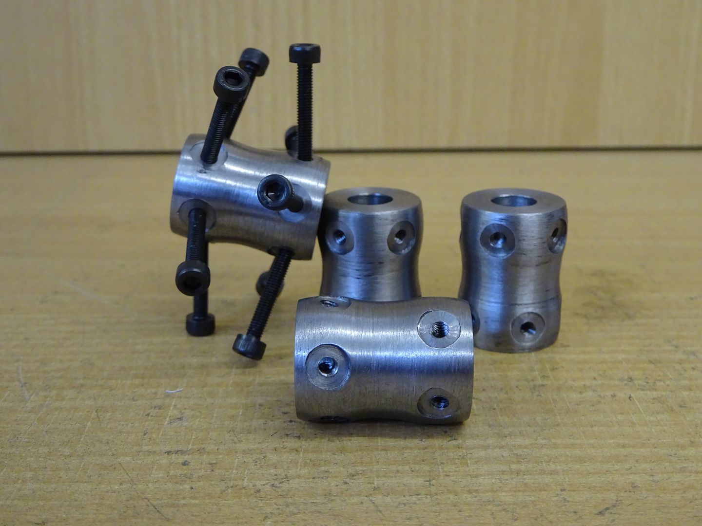
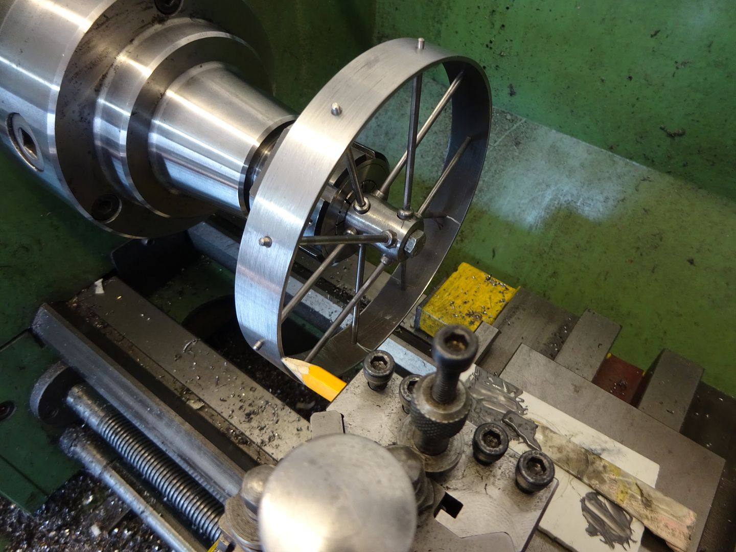
          I also made a start on the cartwheels by machining the hubs, I have poped a few screws into one of them so you can get an idea of where I'm aiming.

          J

          #288533
          Rainbows
          Participant
            @rainbows

            dscf0022.jpg

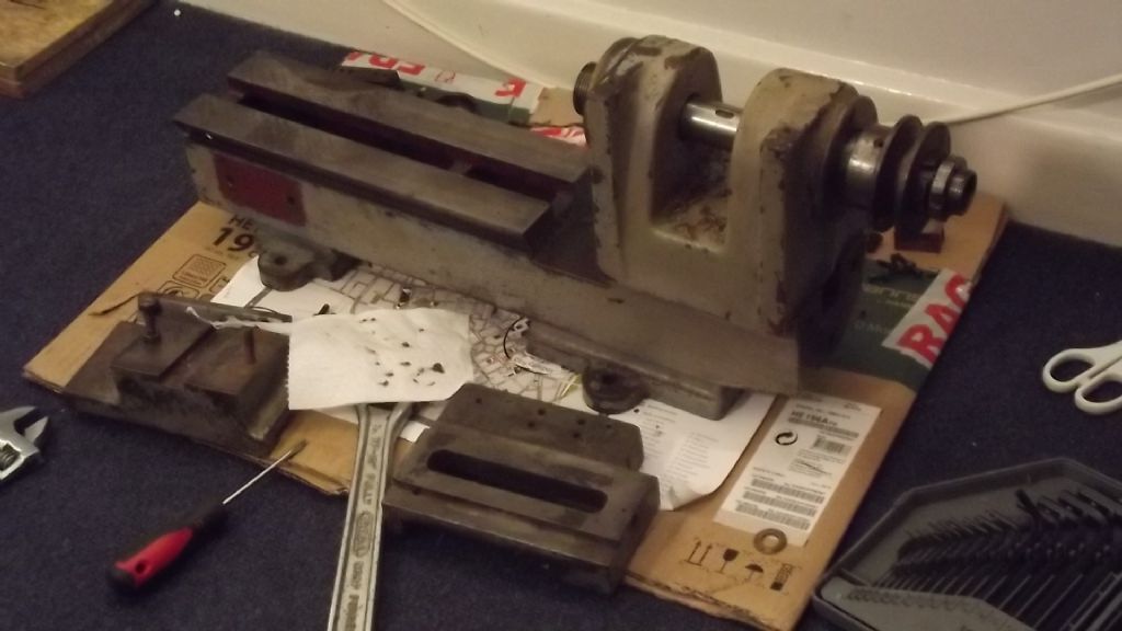
            Now own 3 lathes, will make a thread about it later

            #288845
            duncan webster 1
            Participant
              @duncanwebster1
              Posted by duncan webster on 05/03/2017 19:51:59:

              img_2936 (small).jpgJust to show that I do make stuff now and again, here's some pictures of the bogies for a new club riding truckimg_2937 (small).jpg

              Progress report, here's the main steel chassis, all it needs now is skirts, paint brake levers and final assembly. I'm hoping anothert club member will step up to the plate!

              img_2939 (small).jpg

              #288871
              mechman48
              Participant
                @mechman48

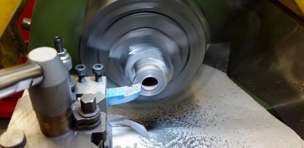
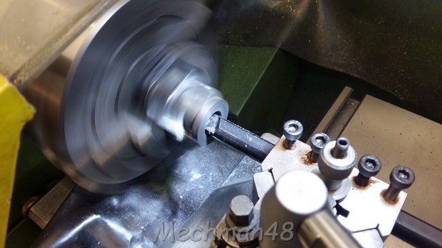
                Yesterday… Machined the cylinder of my S50 stationary engine…

                Flanges…

                s50 stat.eng. machining cylinder (1).jpg

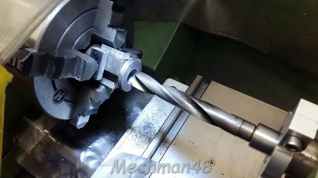
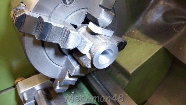
                ​Used 9/16 drill to minimise boring cyl….

                s50 stat.eng. machining cylinder (2).jpg

                ​Boring !…

                s50 stat.eng. machining cylinder (3).jpg

                ​Bore finish looks pretty good… & its bang on .625"… this end; will check for parallelism all the way through bore as usually there is some difference by the time machining is completed… for me! so some judicious honing may be called for?

                s50 stat.eng. machining cylinder (4).jpg

                ​George.


                Edited By JasonB on 15/03/2017 08:40:27

                #288881
                mechman48
                Participant
                  @mechman48

                  Thanks JasonB.

                  Geo.

                  #289296
                  mechman48
                  Participant
                    @mechman48

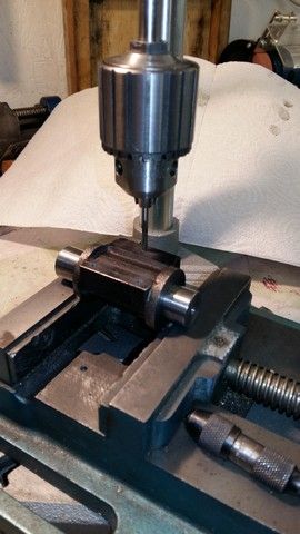
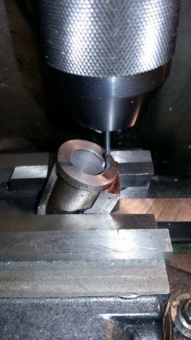
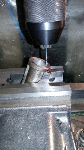
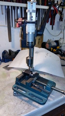
                    Update on my S50 progress, drilled & tapped cylinder fastening holes, drilling steam ports, or in my case air passages, plus a concocted home made tapping stand…

                    09 -s50 drilling .tapping cylinder fixing holes (1).jpg

                    09 -s50 drilling .tapping cylinder fixing holes (2).jpg

                    09 -s50 drilling .tapping cylinder fixing holes (3).jpg
                    Drilling angle worked out at 21*…

                    ​Home made tapping stand…

                    home made tapping stand.jpg

                    ​George.

                    #289519
                    JasonB
                    Moderator
                      @jasonb

                      One of the challenges of taking on a part made model is finding the unique features that the previous builder managed to incorporate into the build.

                      After spending over an hour scraping the big end bearing to fit the crank which had a pin that was not only concave but also tapered across its width I thought I would see how the engine turned over with the piston in place. Try as I might I could not get the cylinder to sit down on the flange at the top of the crankcase. A bit of work on a flat surface with the height gauge and all became clear.

                      God knows how he did it but the flange slopes 0.067" over its 2.5" widthcrook


                      Edited By JasonB on 19/03/2017 17:45:47

                      #290252
                      Muzzer
                      Participant
                        @muzzer

                        It seems to have been fairly quiet in the MEW workshop judging by the lack of postings recently. I've been pretty busy myself since I got back from China a week ago. The jet lag actually assisted by ensuring I was up and about before 7am most days. Over the weekend and during the evenings I've been unpacking my tools and tooling, moving benches, machines, shelves, cupboards etc to where I think they need to be, recommissioning my machines (after long 2 years in storage), finishing off the 2nd fix work etc.
                        Yesterday I got the building work completion certificate signed off. I got my electrical work inspected, tested and signed off a month ago and all that remained was to check out the interconnected fire system, auto door closer and extraction fans. Job done.

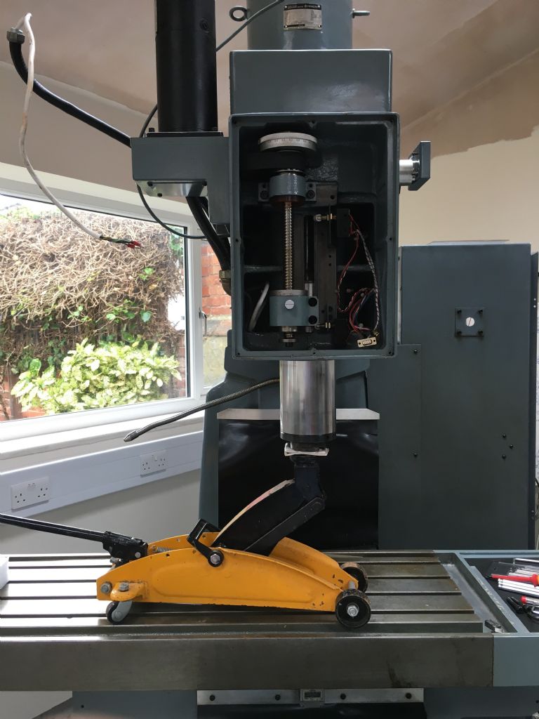
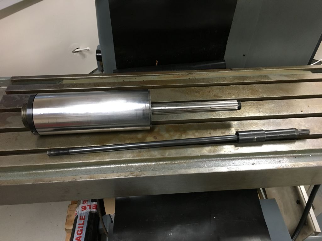
                        I've also been doing more work on the Shizuoka CNC milling machine. Having overhauled and replaced the X and Y axis leadscrew bearings before my travels, I moved on to the spindle and quill. It didn't sound or feel right to me and was actually quite difficult to turn when I first got the machine. It had been in storage (industrial unit) for 10 years but there were no signs of water damage on any of the exposed metal. I may never know what the problem was.

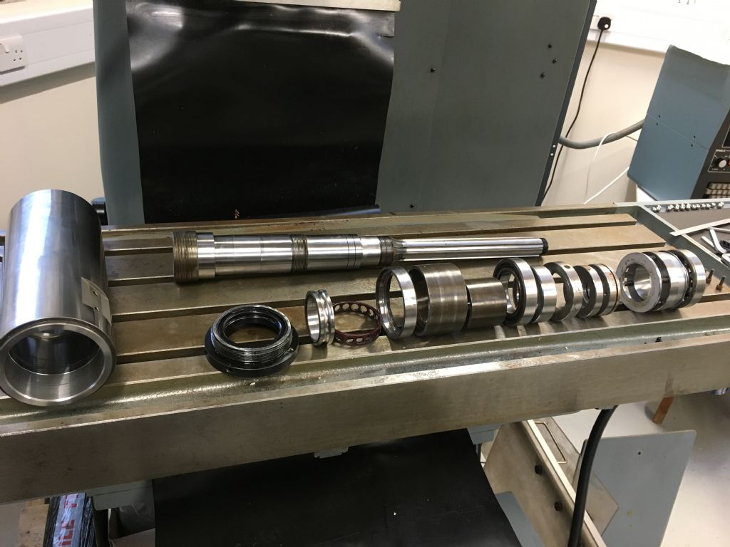
                        I dropped the quill, using a trolley jack to control its descent(!), then dissassembled the spindle and bearings. I was relieved to find that the 3 bearings are fairly standard sizes and I was able to get good quality replacements from The Bearing Boys – a pair of matched Nachi angular thrust (main) bearings and an SKF radial (top) bearing. Some change from £200, so could have been worse. Now feels and sounds a lot happier.

                        img_3286.jpg

                        img_3345.jpg

                        img_3355.jpg

                        On the good news front, I also recommissioned the Bridgeport clone milling machine (VFD, DRO, power feed, quick change drawbar etc). On the not so good front, the ancient controller on the CNC mill has just died. I'd hoped to reverse engineer the existing servo drives while they still worked but that would be pretty tough to do on a dead system. I reckon the CNC gods are telling me something. So I will need to rip all of the 1980s electronics from the control cabinet and set about installing the Chinese controller I brought back in the luggage last week from scratch.

                        Murray

                        #290253
                        MW
                        Participant
                          @mw27036
                          Posted by JasonB on 19/03/2017 17:44:52:

                          One of the challenges of taking on a part made model is finding the unique features that the previous builder managed to incorporate into the build.

                          God knows how he did it but the flange slopes 0.067" over its 2.5" widthcrook

                          Whoa, that must've been a hair raising experience turning with the runout that big!

                          Michael W

                          #290658
                          JasonB
                          Moderator
                            @jasonb

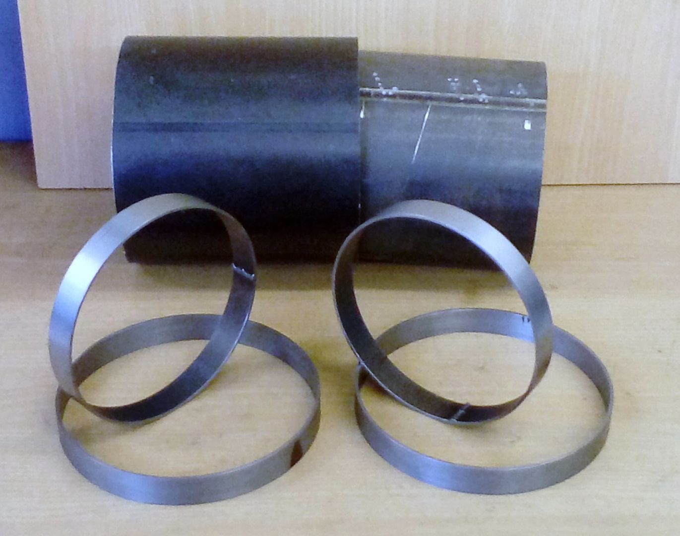
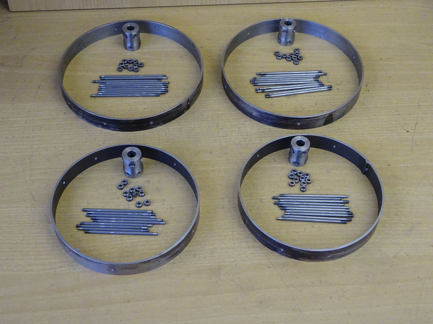
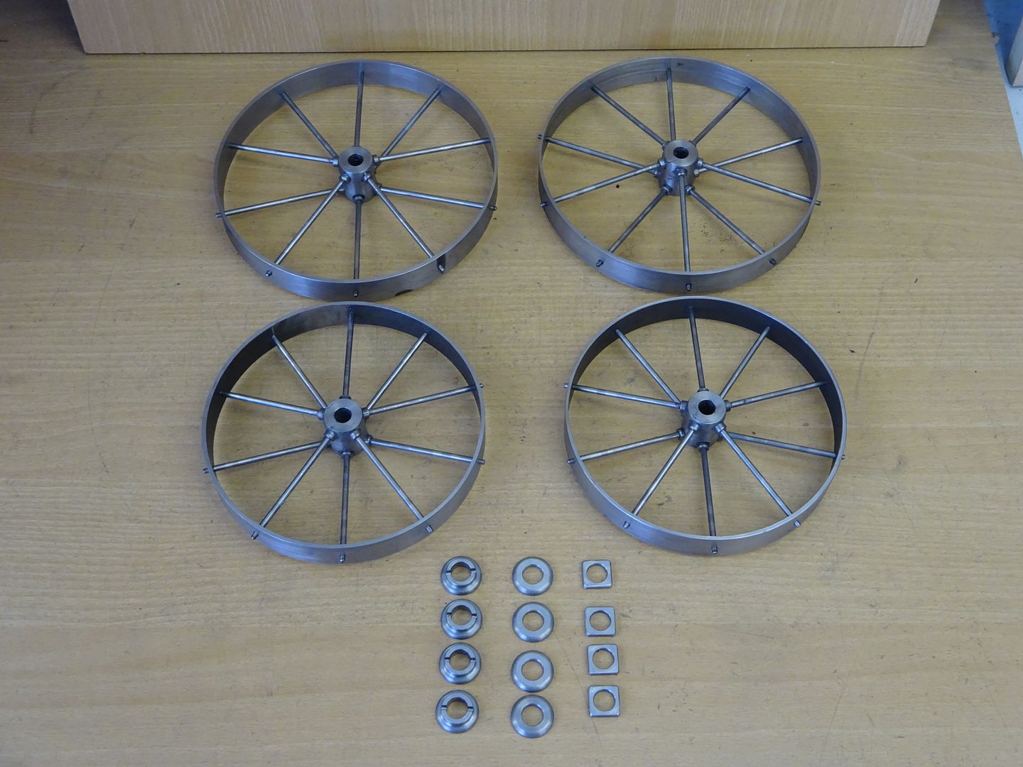
                            I've mostly been doing cart wheels this weekend

                            Started by thinning down some rings cut from ERW tube

                            Added 40 spokes and 40 nipples

                            Trued them up with some JBWeld on the spoke threads.

                            Will give the JBWeld a couple of days to harden up then rivit over the spoke ends

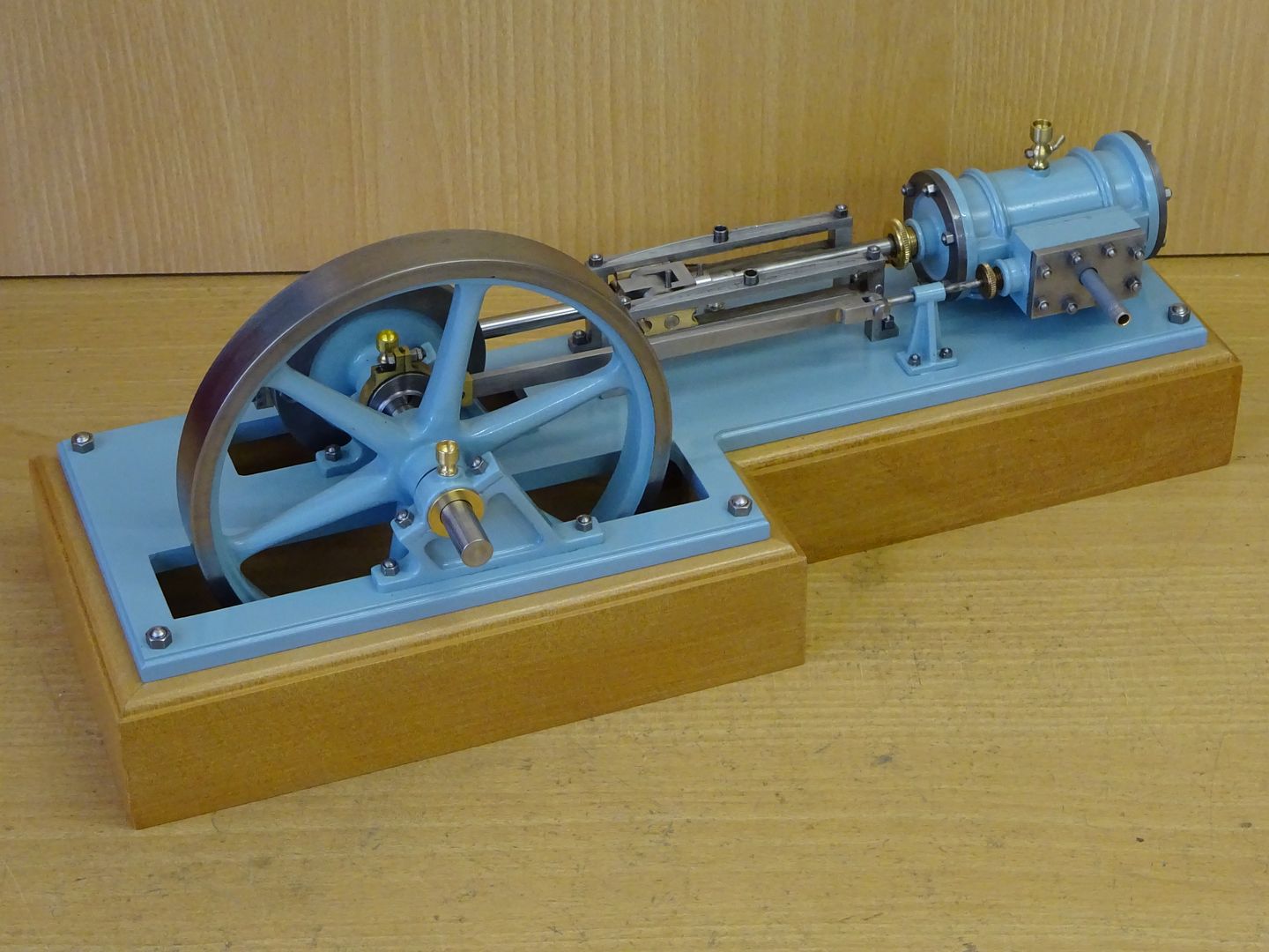
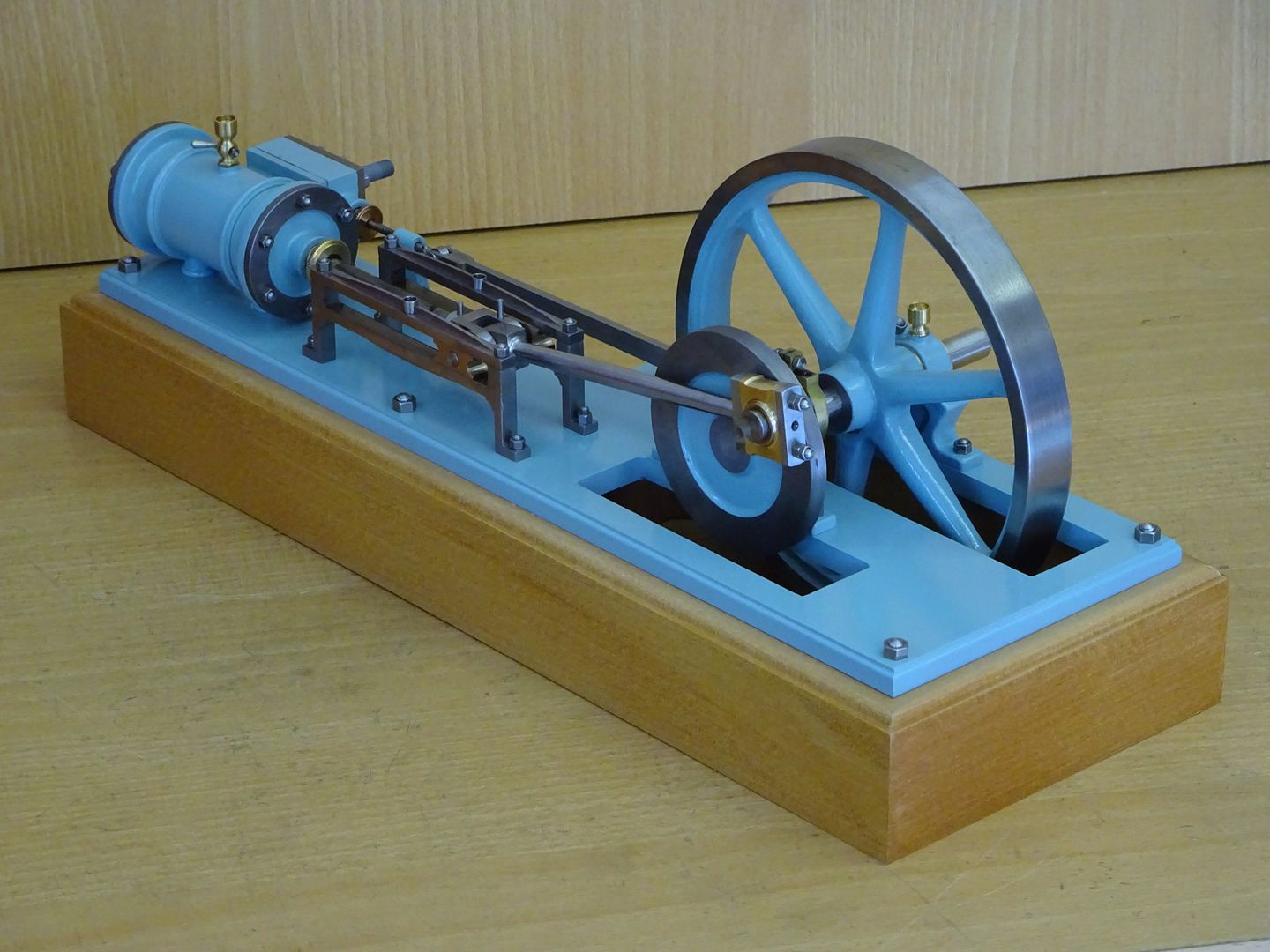
                            Also got the Thompstone Workshop Engine onto its base

                            Then had a play

                            J

                            #290664
                            Jim Nic
                            Participant
                              @jimnic

                              I like the Thompstone Engine, beautifully done. Your engines always run a lot quieter than mine Jason, I must have further to go than I thought to get to your standard of building. crying

                              Did you fabricate the flywheel?

                              Jim

                              #290667
                              JasonB
                              Moderator
                                @jasonb

                                Flywheel was the only bought in item, it's a 125mm one from TS in Germany but worked out a bit pricy so I'll probably suggest the slightly larger Unicorn one from Reeves when I draw it up. Would suit your spare 24mm O ringwink

                                Edited By JasonB on 26/03/2017 17:55:38

                                #290676
                                Jeff Dayman
                                Participant
                                  @jeffdayman43397

                                  Beautiful work Jason. Well done! JD

                                  #290946
                                  Jim Nic
                                  Participant
                                    @jimnic

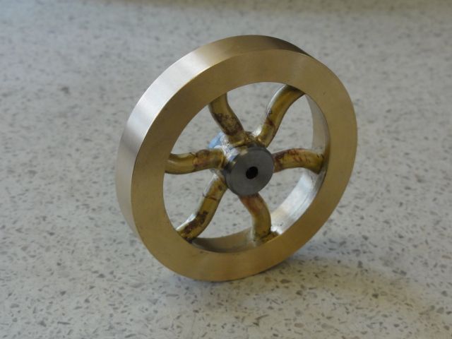
                                    My latest project is the Popcorn Engine designed by Stew Hart. One of the reasons I was attracted to it was that it lends itself to a bit of "bling" and part of that is the curly spokes in the flywheel. They looked a bit tricky, so that was where I started. After a couple of failed attempts I devised a way of making the spokes to a consistent shape and the result is:

                                    Just remains to add a bit of filler round the spoke ends at the rim, a coat of bright red paint and polish a shiny finish on the rim and it's onto the next bit, the cylinder block.

                                    Jim

                                    Edited By Jim Nic on 28/03/2017 17:02:04

                                    #290952
                                    JasonB
                                    Moderator
                                      @jasonb

                                      You're off to a good start.

                                      #291059
                                      Ian S C
                                      Participant
                                        @iansc

                                        Jason, just a query about the bearing mounting on your engine, the thrust appears to be on the bearing caps? On IC motors with angled bearing pillars the slope seems to be the other way round so that the thrust is into the lower section , the cap mearly holding the bearing in place, and not taking a load.

                                        Ian S C

                                        #291063
                                        mechman48
                                        Participant
                                          @mechman48

                                          Beautiful Thompstone engine Jason; like the colour, what is it, sky/duck egg blue? different from the usual Stuart type green & red, black norm, makes it more individualistic.

                                          ​George.

                                          #291067
                                          JasonB
                                          Moderator
                                            @jasonb

                                            Ian, its a point that took me a while to commit to, as you say if the angle was the other way then the pedestals would be taking thrust as they do on an IC engine.

                                            However, steam engines are double acting so there is an equal force as the piston moves away from the cylinder as well as when it moves towards the cylinder. On an IC engine the thrust is all on the downstroke.

                                            I also looked through a lot of similar style engines on the net and there was a fairly even spread between upright, facing the cylinder and facing away. Final decider was that the general arrangement drawing back in the old ME has them the way I have built it.

                                            George, the colour is actually Forn "Nordiv Blue" which is along the lines of a duck egg blue. I'll try and take some better photos at the weekend using my old setup rather than the wooden background that I have in the workshop as that does funny things to the colours.

                                            J

                                            #291077
                                            Martin Kyte
                                            Participant
                                              @martinkyte99762

                                              To me, it's not as bad as it looks (bearing thrust not the engine). Assuming that the video shows normal operation and mill engines didn't need to run in reverse then the 'pull stroke' is above flywheel centre and into the lower part of the bearing and the push stroke is below the centre and mostly in the lower half. Could it be that with bearing stands angled as shown you can adjust the horizontal centre distance (flywheel to cylinder middle by packing the bearing brasses up or down and thereby evening out the stroke at either end of the cylinder.

                                              regards Martin

                                              #291244
                                              Ian S C
                                              Participant
                                                @iansc

                                                I suspect the bearings are mounted that way to take the belt load rather than the engine load, I think most steam engines I have seen are level on the bearing split.

                                                Ian S C

                                                #291510
                                                Steven Greenhough
                                                Participant
                                                  @stevengreenhough56335

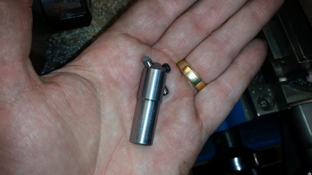
                                                  Made a little fly cutter-cum-boring type tool…

                                                  Oh badger will add pic from PC in a while…

                                                  Edited By Steven Greenhough on 31/03/2017 19:25:15

                                                  #291522
                                                  Steven Greenhough
                                                  Participant
                                                    @stevengreenhough56335

                                                    As promised…

                                                    20170331_191401.jpg

                                                    #291745
                                                    mechman48
                                                    Participant
                                                      @mechman48

                                                      Made up the crankshaft, web & crankpin for my S50 engine…
                                                      020-s50 crank assembly (1).jpg

                                                      022-s50 crank assembly (3).jpg

                                                      ​George.

                                                    Viewing 25 posts - 126 through 150 (of 356 total)
                                                    • Please log in to reply to this topic. Registering is free and easy using the links on the menu at the top of this page.

                                                    Advert

                                                    Latest Replies

                                                    Viewing 25 topics - 1 through 25 (of 25 total)
                                                    Viewing 25 topics - 1 through 25 (of 25 total)

                                                    View full reply list.

                                                    Advert

                                                    Newsletter Sign-up