The Workshop Progress Thread (2016)

Advert

The Workshop Progress Thread (2016)

Home Forums Work In Progress and completed items The Workshop Progress Thread (2016)

Viewing 25 posts - 201 through 225 (of 457 total)
  • Author
    Posts
  • #236066
    Anonymous

      Jason: That's an excellent looking finish on EN8. Any info on speeds and feeds? With ordinary CCMT inserts I found I could get a good finish on EN8 but I had to run fast. If I recall correctly I was running a 1-5/8" bar at 1200rpm.

      Andrew

      Advert
      #236093
      JasonB
      Moderator
        @jasonb

        Andrew I tried a few different tools and tips as I got towards the finished 7/16" dia. My usual CCMT * and DCMT tips were tearing at the surface a lot, HSS was better but not ideal so I tried one of the tips for Aluminium from APT once it was down to 1/2" dia. Took it down in two 0.010" cuts and two 0.005" cuts, I saw your post a day or two ago about high speeds to finish EN8 so used 1100rpm (highest without changing the belts) and it took a very nice cut.Feed was my slowest of 0.00075/rev with a bit of soluable oil brushed on.

        J

        * My CCMT holders are 6 & 8mm which did not help as I needed to extend the tool so the toolpost cleared the live ctr, the DCMT is a bit stiffer at 10mm Sq.

        #236216
        Anonymous

          Jason: Thanks for the information. Tearing was the result I got with insert tooling at slow surface speeds. I didn't try HSS. It's interesting that you got a good finish with relatively small DOC and a very fine feed. I think my lathe will go down to 1 thou/rev, but I've never used it. I normally use 4 thou/rev for finishing. May be I need to experiment more.

          Andrew

          #236233
          JasonB
          Moderator
            @jasonb

            Should have said I was also using 0.2mm tip radius which I feel needs the finer feeds to avoid producing a fine thread! Also on the cranks I find deflection can start to become a problem if too heavy a cut is taken, this one was quite short at 5" but some of teh hit & miss engines are getting towards 12" long.

            #236287
            Brian Abbott
            Participant
              @brianabbott67793

              Hello Jason.

              ( Warning. amateur hour )

              Can i ask why you use En8 instead of say mild steel ?

              #236310
              JasonB
              Moderator
                @jasonb

                It's probably force of habbit as I use it on all the higher reving 2 and 4 stroke engine cranks, its got a higher tensile strength than say EN1A so should be a bit stronger and is quite often specified on other designs..

                #236359
                Brian Abbott
                Participant
                  @brianabbott67793

                  Thanks Jason, only wondered as I am about to start the crank on my Minnie and am worried about turning a nice finish to run through the bearings.

                  #236376
                  JasonB
                  Moderator
                    @jasonb

                    I'd probably do that as a built up crank as per the book, if you use PGMS (precision ground mild steel) you won't have anything to do to the shafts. If you do want to make from solid then EN1A should be fine at the slower more gentle pace of teh small Minnie.

                    #236422
                    Brian Abbott
                    Participant
                      @brianabbott67793

                      Hello Jason,

                      Do you know where i can buy PGMS from ?

                      #236434
                      mechman48
                      Participant
                        @mechman48

                        Was continuing on with my S10V, at the crankshaft stage, screwed up the first one due to measurements not working out so started on new one, still had bit of misalignment on the web holes even though they were soldered & drilled together. Further investigation showed that my bench drill table was out of square to the quill by some noticeable amount, so the S10V was put on hold & the drill table removed & checked. found that the recess in the table was off centre to the boss on the pillar bracket plus full of paint, & the hole for the clamping bolt was off centre…

                        Front mis-alignment… this will need some work doing on the recess of the casting

                        bench drill table mis-alignment (1).jpg

                        Side mis-alignment…

                        bench drill table mis-alignment (4).jpg

                        Side can be realigned as it is a rotational adjustment of the table, although the zero lines up with the fiducal line on the scale it's obvious that the scale is not accurately located … by the way the square blade is central to the silver steel rod in both pics although it doesn't look it

                        Off centre machining of casting, the recess does not align with the boss on the pillar casting properly when the clamping bolt is fitted, plus all the paint in there…

                        bench drill table mis-alignment (5).jpg

                        Some dremel work needed here to clean out the casting & paintwork, have started to scrape of the paint down to bare metal, will set the table up on the mill with the table face clamped to an angle plate & lightly skim this face to clean up & create a 90* angle to the table face… pity my lathe is not big enough to allow me to skim the face & the recess bottom parallel, & centralise the hole…  mind you got the drill very cheap from private sale so … also can't guarantee that the quill is machined / fitted square in the head casting either, will need to check that out with dial indicator… if that's out, well …  thinking …  Ho hum; the vagaries of Chinese machining, some good, some crap… face 19

                        George.


                        Edited By mechman48 on 27/04/2016 12:05:23

                        #236459
                        JasonB
                        Moderator
                          @jasonb

                          Brian you should be able toi get it from the folowing

                          College Engineering

                          EKP

                          M-Machine

                          #236460
                          Brian Abbott
                          Participant
                            @brianabbott67793

                            Thanks Jason.

                            #236614
                            Anonymous
                              Posted by JasonB on 26/04/2016 07:12:34:

                              Should have said I was also using 0.2mm tip radius which I feel needs the finer feeds to avoid producing a fine thread!

                              Indeed. I did a sketch and measurements, and then realised you were using a DCMT style insert, not CCMT, so my numbers are nonsense. Of course all feeds produce a thread, it's just a case of how deep the 'thread' is!

                              I'm planning some experiments on surface roughness versus various types of tooling, so I'll add finish versus feedrate as a parameter to explore.

                              Andrew

                              #236616
                              JasonB
                              Moderator
                                @jasonb

                                Look forward to it Andrew, will you be trying a few different tip radii?

                                #236626
                                Rod Neep
                                Participant
                                  @rodneep80388

                                  A new milestone for me today…. my first milling machine.

                                  A SIEG Super X2 Hi-Torque with brushless motor from AET, plus a vice and some other nice things to play with.

                                  Pretty good service from AET…. I ordered it yesterday and it was delivered today.

                                  Spoke nicely the the guy delivering it, and he kindly wiggled it through the door into my workshop for me. I have broken it out of its case and palette and now its a matter of getting the help of a couple of burly lads (my sons) to lift it onto its new crimson stand next time they visit. (Or hire a lift if I run out of patience).

                                  A whole new learning curve coming up. surprise

                                  Rod

                                  Edited By Rod Neep on 29/04/2016 00:20:36

                                  Edited By Rod Neep on 29/04/2016 00:22:55

                                  #236768
                                  Anonymous

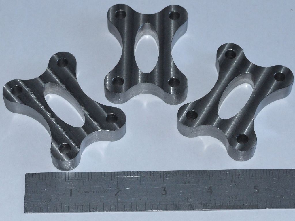
                                    Got fed up with work admin so I took a half day off and finished off the traction engine water pump spacers:

                                    water_pump_spacers.jpg

                                    Why the fancy shape? Just for the hell of it!

                                    Andrew

                                    #236770
                                    JasonB
                                    Moderator
                                      @jasonb
                                      Posted by Andrew Johnston on 29/04/2016 19:40:20:

                                      Why the fancy shape? Just for the hell of it!

                                      Andrew

                                      That won't please the rivit counters smile p but I suppose if you have a CNC then why not play with it. Was there some form of spacer on the originals or are they needed due to the redisigned pump?

                                      #236819
                                      Anonymous
                                        Posted by JasonB on 29/04/2016 19:51:20:

                                        That won't please the rivit counters

                                        The rivet counters know where they can go; and if not I'm happy to spell it out for them. wink 2

                                        The full size water pump had a flange as part of the casting rather than a separate spacer. The LSM drawings have a note on the top view of the water pump saying 1/2" packer, with no further details. My spacer is 0.451" partly because my hornplates are 6mm rather than 1/4" and partly because the drawings are nonsense.

                                        Andrew

                                        #237077
                                        JasonB
                                        Moderator
                                          @jasonb

                                          Turned one side of the Lightweights flywheel from a bit of 4" steel, not too worried about finish as it will be roughed up with the Dremel to look cast.

                                          Then cut the taper on the crank followed by the other side of the flywheel and it's tapered bore while the topslide was at the same angle. Boring bar upside down and cutting at the back but rotating in the usual direction.

                                          #237082
                                          Iain Downs
                                          Participant
                                            @iaindowns78295

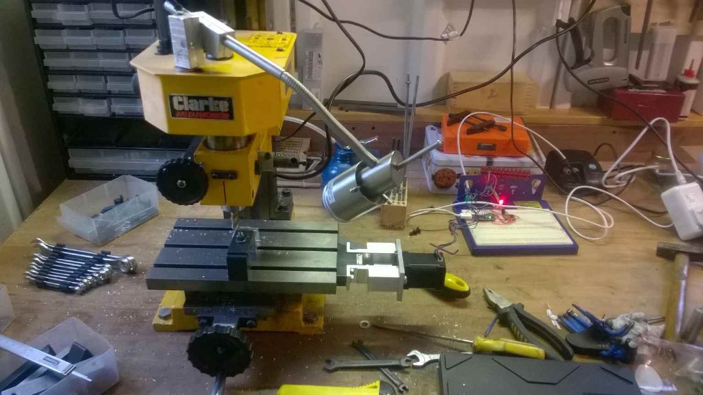
                                            Finally! I've made some progress with CNCing my mill.

                                            I was going to use a raspberry pi to drive the motors, but when I checked with a scope the (simple) timer approach was missing beats. So I pulled an Arduino Nano (one I'd bought on spec earlier!) out and set that up. This time I actually used a breadboard (seen in a picture below) rather than soldering the thing up on stripboard. Considerably quicker!

                                            The arduino is dead easy to program for, though I may end up putting something called GRBL on it which does the CNC interpretation / heavy lifting, but may main objective is to use it to surface large (relatively) plates without me dying of boredom..

                                            I've found that a 60NM NEMA 17 motor is strong enough (the NEMA 14 motors I had kicking around were not). Though the mill (CMD10) has to be set up dead on or the table is too stiff for the motor to be turned(or too stiff in some places).

                                            cnc x axis full.jpg

                                            I've milled some aluminium and then -heart in mouth- some mild steel! I seem to be able to take a 1mm cut at around 2mm / sec (one handle turn, I think though I will calibrate this properly later).

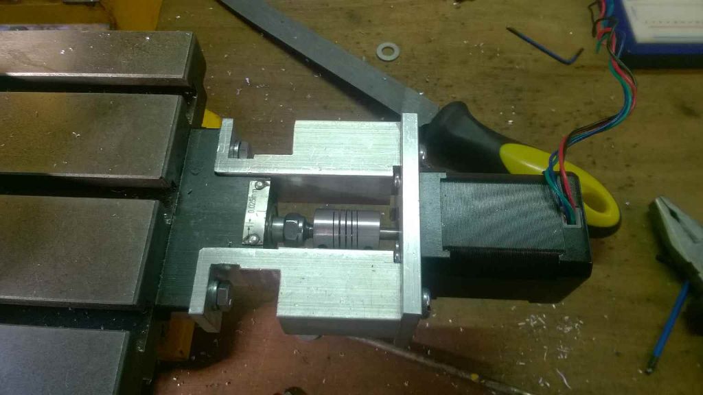
                                            What I'd like to do is to find a motor with the same power and size which has got a axle sticking out the back as well as the front so I can put a turn wheel on it. Failing that I've got some quadrature encoders on order which I can use to input manually. It's a level of indirection I don't much care for if I can avoid it. There's a level of feedback through the wheel which just occasionally stops you breaking the damned gears (again).

                                            Here's a close up of the mount.

                                            cnc x axis close up.jpg

                                            Next step is another motor and mount for the Y axis and to turn a test harness into a program.

                                            Iain

                                            #237122
                                            Martin Cottrell
                                            Participant
                                              @martincottrell21329

                                              Today I was faced with the challenge of drilling 2 rows of 24 equally spaced rivet holes around the front and rear edges of my traction engine smokebox tube. Ordinarily a fairly straightforward job mounted on the rotary table in the mill however the challenge arose because the smokebox tube is 9" diameter and my rotary table is only 6"diameter.

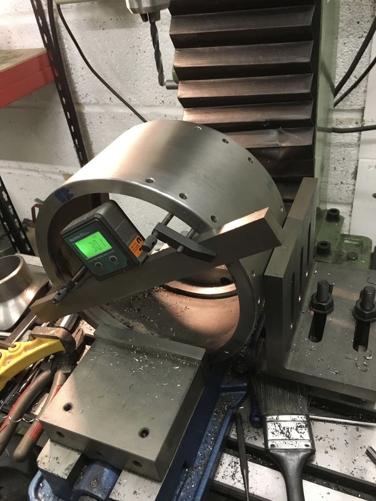
                                              I had intended bolting a 9 1/2" diam aluminium plate to the rotary table and clamping the smokebox to this extended 'faceplate", then sorting a suitable raising block under the RT to raise the centre height so that the faceplate would clear the mill table. This all seemed a bit of a precarious and fiddly set up and whilst pondering alternative methods I hit on the idea of using my Wixey digital angle gauge to index the 24 hole positions around the smokebox. The smokebox fitted nicely in my machine vice on the mill table and a large angle plate was used as a fence to maintain the smokebox in the correct position as it was rotated for the next hole. I clamped a sturdy bar across the smokebox to mount the angle gauge on then proceeded to do a trial "lap" of the smokebox indexing every 15 degrees as I went. The bar had to be reset a few times when it came close to fouling the vice jaws which I thought might introduce errors but my trial lap ended in the drill being approx 0.030" out when lined up with the original starting point. Not much use for gear cutting but certainly good enough for my 2 rings of rivet holes. So, happy that everything would work I set about drilling the front & rear holes then indexed around to the next station and had the whole job done from idea to completion in about 1 1/2 hours, probably quicker than I would have taken just to set up my original idea.

                                              The photo below shows my setup in progress. I certainly don't claim any originality for the method used although it is not a method that I have seen described before so thought it might be of use to someone else who reads it!

                                              Martin.

                                              thumb_img_0395_1024.jpg

                                              #237163
                                              Rod Neep
                                              Participant
                                                @rodneep80388

                                                My new SIEG Super X2P HiTorque Mill – Belt Drive with Brushless Motor is now set up and ready to use. I was pleasantly surprised how quiet it is!

                                                Got to thinking about adding a 3 axis DRO set, but the price of £394 for a full (waterproof) set made me pause. Until I found exactly the same set direct from China at £73. I might well go for that, and wile I am at it, buy a set for the lathe too.

                                                Rod

                                                #237220
                                                Anonymous

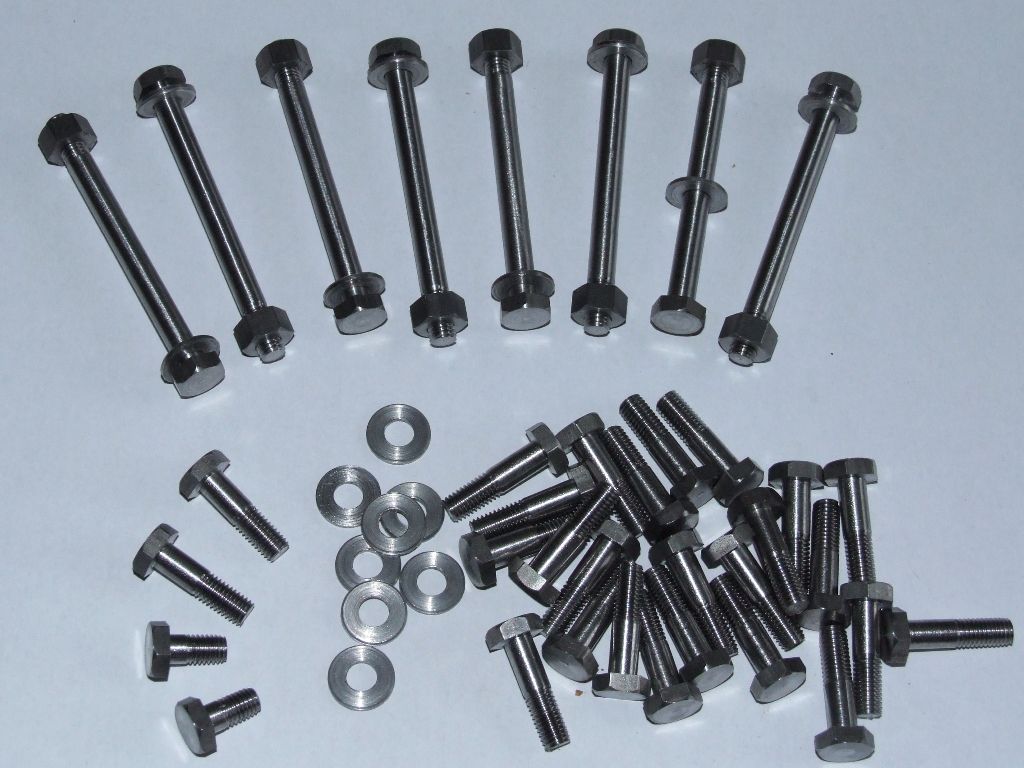
                                                  It's been raining today, so I've had a session on the repetition lathe making bolts and washers (plus the nuts I made earlier) for the water pumps and crankshaft bearing housings. Bottom left are some special bolts for holding the gear change castings to the hornplates. All threads are 1/4" BSF:

                                                  bolts nuts washers.jpg

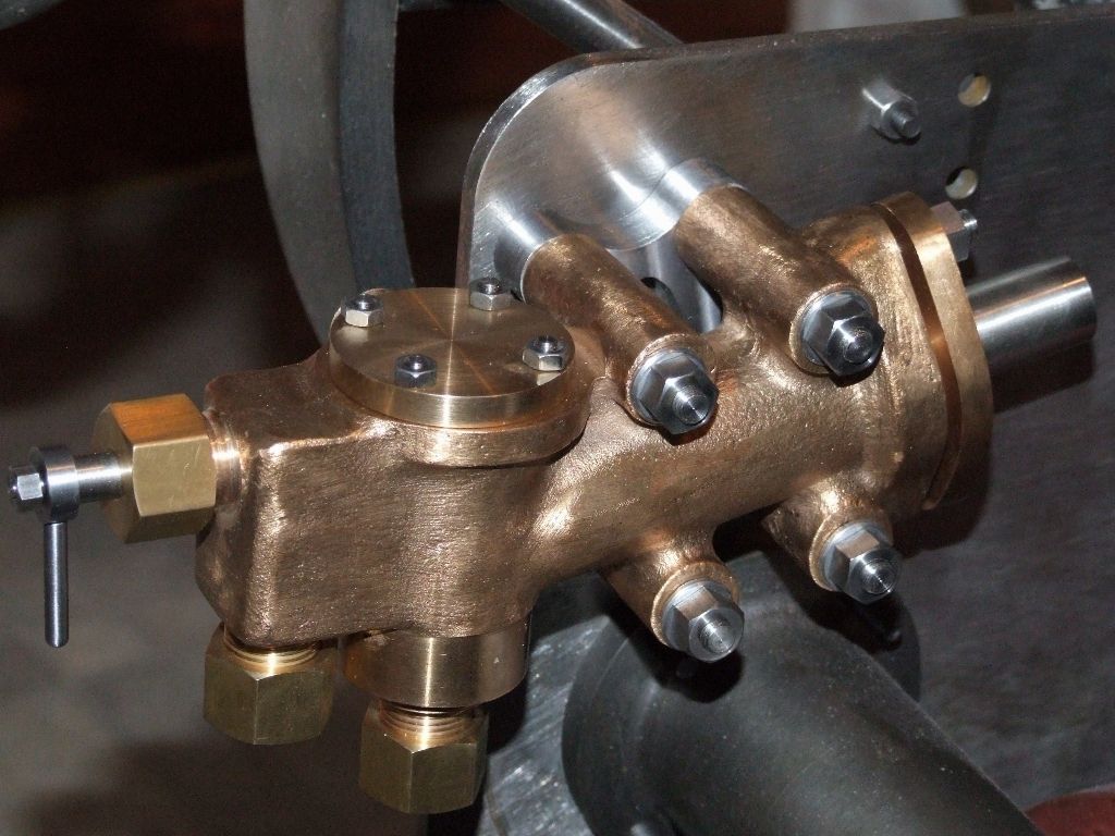
                                                  That should make the rivet counters bolt up! And here's the water pump in situ, with the proper bolts and fancy spacer:

                                                  water pump in situ.jpg

                                                  Andrew

                                                  #237221
                                                  Muzzer
                                                  Participant
                                                    @muzzer

                                                    Very nice! What material did you use? Coventry die head for the threading?

                                                    #237231
                                                    Anonymous
                                                      Posted by Muzzer on 02/05/2016 19:10:07:

                                                      Very nice! What material did you use? Coventry die head for the threading?

                                                      Everything made from EN3B, and yes I used a Coventry diehead. I learnt something about Coventry dieheads though. Initially I lightly chamfered the unthreaded end of each bolt for neatness. But I had all sorts of problems getting the diehead to start. Once it did, it sometimes left a tapered start to the thread. No chamfer and the diehead started without a problem. Another lesson learnt.

                                                      Andrew

                                                    Viewing 25 posts - 201 through 225 (of 457 total)
                                                    • Please log in to reply to this topic. Registering is free and easy using the links on the menu at the top of this page.

                                                    Advert

                                                    Latest Replies

                                                    Viewing 25 topics - 1 through 25 (of 25 total)
                                                    Viewing 25 topics - 1 through 25 (of 25 total)

                                                    View full reply list.

                                                    Advert

                                                    Newsletter Sign-up