The Workshop Progress Thread (2016)

Advert

The Workshop Progress Thread (2016)

Home Forums Work In Progress and completed items The Workshop Progress Thread (2016)

Viewing 25 posts - 51 through 75 (of 457 total)
  • Author
    Posts
  • #222610
    Steve Pavey
    Participant
      @stevepavey65865
      Posted by JasonB on 24/01/2016 20:03:11:

      Steve, I'll be doing a full write up of the build with lots of pictures once I know it's a runner but until then.

      J

      Nice one. It looks like 24 cuts for the semi-circle to me, must have been very satisfying to see it taking shape.

      Advert
      #223230
      JasonB
      Moderator
        @jasonb

        Well I got teh conrod for teh Jowitt finished last night and did the two flywheels this morning so just had to see what happened with a bit of air. It did about 3 revs than stopped each time I flicked teh flywheel so lengthened the inlet valve slightly which improved things then moved the exhaust eccentric about 20degrees and away it went. Few studs to make and some tidying up then a lick of paint.

        Also helps if you don't turm teh compressor regulator right down when doing a test run blush, chuff, chuff

        J

        Edited By JasonB on 30/01/2016 16:40:06

        #223235
        Nick_G
        Participant
          @nick_g

          .

          Nice Jason. smiley

          Strange for you to build such a small engine un-all. laugh

          Nick

          #223238
          JasonB
          Moderator
            @jasonb

            Thanks Nick. I did infact make it bigger than the original drawings by about 30%. Though as you say its still a little un but quite an enjoyable quick project – started 2nd Jan.

            #223248
            SteveW
            Participant
              @stevew54046

              That is a lovely engine. Sounds good too. Looks good naked but I expect you've got a paint scheme in mind. Hope there will some plans sometime!

              #223392
              Anonymous

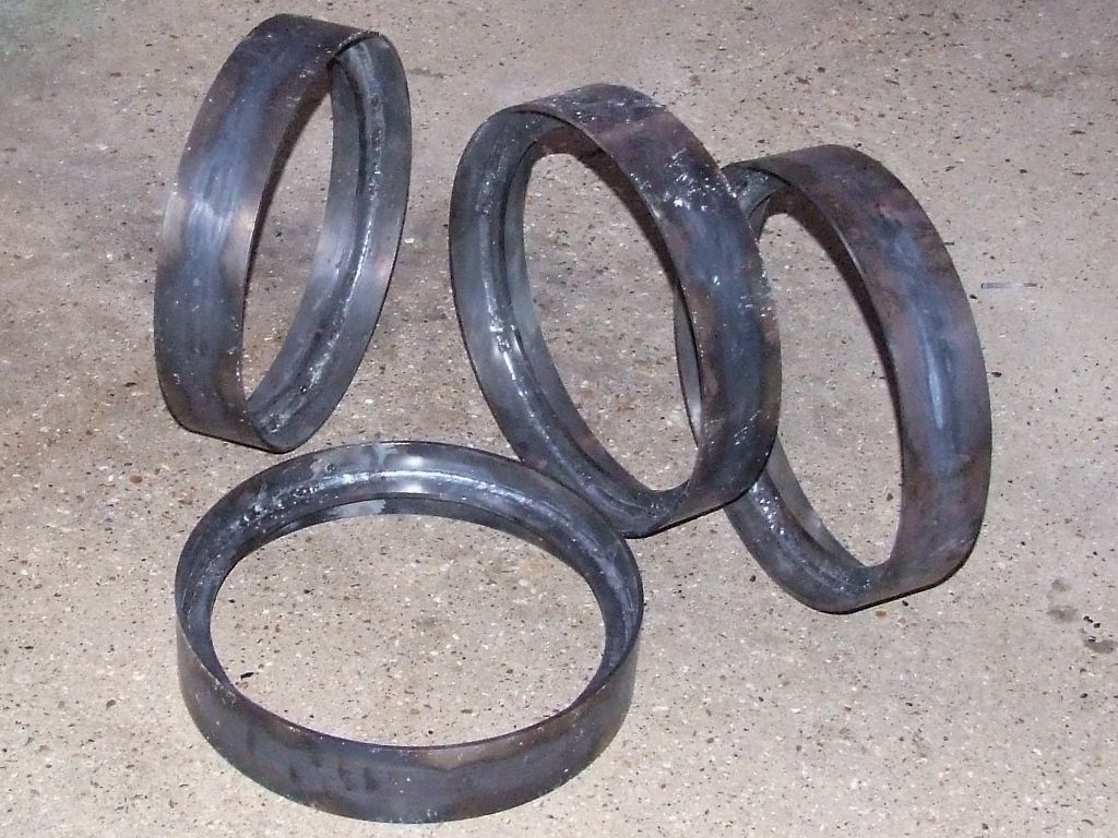
                After a mammoth welding session this afternoon all four front wheel rims and T-rings have been welded, including dressing and welding the new rim to replace a previous one I wasn't happy with, more scrap. sad

                front wheel rims.jpg

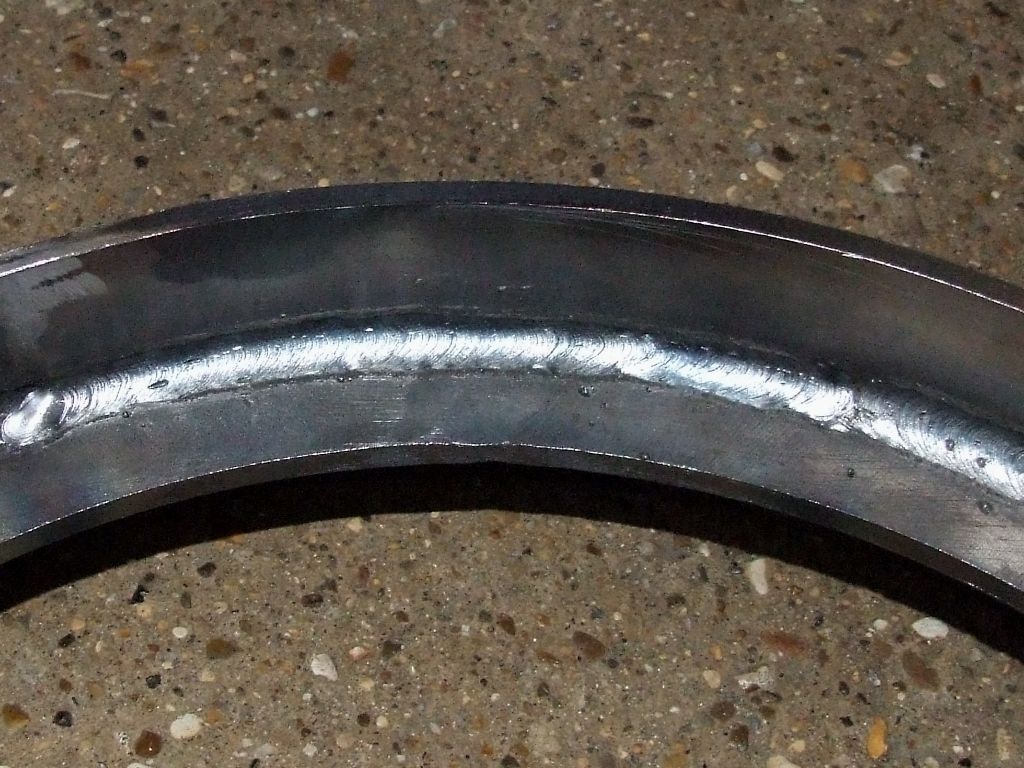
                My arc welding is also improving. I turned the current down to 120A (from 130A) so there's a bit less undercutting. By the time I've finished all the wheels I'll probably be good enough to start again and make the wheels properly!

                front wheel - welding.jpg

                For scale the wheel rim OD is 14.5". Next job is to weld the 32 quadrants together to make the T-rings for the rear wheels.

                Andrew

                Edited By Andrew Johnston on 31/01/2016 19:42:05

                #223400
                Muzzer
                Participant
                  @muzzer

                  Doesn't look too bad at all. Stick or MIG? I'm guessing MIG?

                  #223402
                  Fatgadgi
                  Participant
                    @fatgadgi

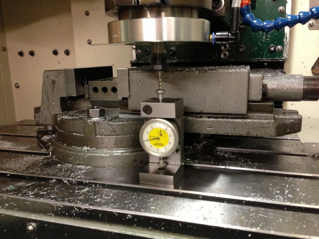
                    A year or so ago I made a height setting gauge for the CNC mill and saved a fortune on the commercial offerings. And it worked a treat.

                    Felt pretty supercilious at the time – used and old dial gauge that had been knocking around for years plus a couple of odd lumps of steel, so zero outlay.

                    img_0627.jpg

                    But not feeling quite so cocky now embarrassed

                    I went to use it yesterday and found it was sticky from the odd dribble of cutting fluid dropped onto it and it wouldn't return by it's own spring pressure after being pushed down.

                    Spent an hour today cleaning the gauge to get it to work smoothly again. But I know it will do the same again if I keep using it. So what to do ?

                    Thought about making an umbrella type shroud to fit the business end and to deflect the drips away from the shaft underneath. Or perhaps put a bigger spring at the bottom to make sure it always moves. As a last resort, perhaps implement an annual maintenance schedule…….

                    But whatever, I refuse to stump up for a proper one. It's a matter of principle !!!

                    Any other bright ideas ?

                    Cheers – Will

                    #223406
                    Peter Krogh
                    Participant
                      @peterkrogh76576

                      Will,

                      My choice would be to make a top contact for the stem that has a drip lip around it so fluid doesn't run down the indicator shaft.

                      Pete

                      #223408
                      Jeff Dayman
                      Participant
                        @jeffdayman43397

                        You could invert the indicator and drive it with a lever. Any coolant drips in that case would have to go back uphill to get in the indicator. I mounted several with a lever as described for high volume aluminum milling in industry, using flood coolant at several gallons per minute. I visited the factory I did one such set for last year. The original mechanical indicators were replaced about 10 yr ago by LVDT units for in-process gauging but my mounts and levers are still in use 22 yr on. JD

                        #223411
                        Anonymous
                          Posted by Muzzer on 31/01/2016 20:34:08:

                          Doesn't look too bad at all. Stick or MIG? I'm guessing MIG?

                          It's arc welded; I don't have a MIG welder. The arc welder function came 'free' with an AC/DC TIG welder. So the arc is derived from an inverter, and is nice and stable.

                          Andrew

                          #223420
                          John Stevenson 1
                          Participant
                            @johnstevenson1

                            Back in harness after having the hobber out of action for three weeks.

                            Probably a full days work if you take all the wasted time out of it and late starts.

                            Normal service will be resumed as soon as me coffee cup is full.

                            #223422
                            John Haine
                            Participant
                              @johnhaine32865

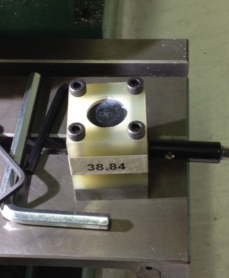
                              Will, this is my home made height setter.

                              image.jpeg

                              The body is made of epoxy fibreglass, with a steel base with a magnet that sticks to the table. There's a tungsten carbide platen in the top that is spring loaded. The platen is isolated from the table, and connected to the probe input of the BoB by the 4mm plug you see to the right. The top of the platen is 38.84 mm above the base. In use I stick it on the table and activate the tool zero button in Mach3. I've written a macro that moves Z down until the tool touches the platen, then retracts a very small amount, moves down very slowly again until it contacts, then lifts up to 50mm above the table surface. Works a treat. Mind you I don't use suds on the cnc mill.

                              #223427
                              Emgee
                              Participant
                                @emgee

                                Hi Will

                                I have the same set-up and found like you the foot didn't return, I added a light spring between the elephants foot and the top plate, the gauge always returns now to the same reading. It won't solve the coolant issue though but if you fit an 'O' ring in the top plate bore above the stem gripping point it would provide a seal against coolant, you may then need a little stronger spring.

                                Emgee

                                #223429
                                Fatgadgi
                                Participant
                                  @fatgadgi

                                  Thanks for the replies so far ….

                                  Jeff – That's a better way to go and in hind sight, I would definitely have done something similar, but I think that I would almost need to start again. I'll try bodging first.

                                  Peter, I'm going to try that first – I'm thinking a plastic drip lip like an inverted bucket, with a smaller cylinder inside it fixed to the body. So a labyrinth, if I can get the geometry right. I may have to cover the whole top surface to guide any drips away from the gauge body as well, although the gunge was only in the moving shaft, not the mechanism.

                                  I think it would be smart to add another spring at the bottom, you're right Emgee. Adding a proper seal with the spring's a good idea. I'll see if I can get a small lip seal or similar and try something.

                                  John, nice solution. Too clever for me, but nice.

                                  Cheers Will

                                  #223430
                                  Peter Krogh
                                  Participant
                                    @peterkrogh76576

                                    Will, I thought that an upsidedown bucket (I like the visualization) would work as it wouldn't impose any drag like a seal would, and could be made light weight so an additional spring wouldn't be required.

                                    I've done this on fixtures a couple of times years ago and it worked out well.

                                    Pete

                                    #223489
                                    Roderick Jenkins
                                    Participant
                                      @roderickjenkins93242

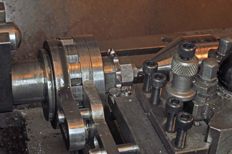
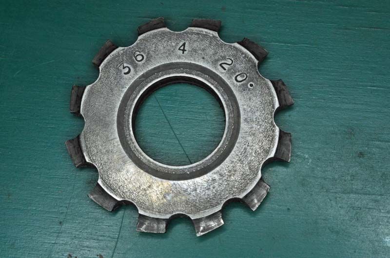
                                      I made a No.4 36DP cutter using the Eureka backer offer:

                                      gc10.jpg

                                      It's silver steel, hardened then lightly tempered at 190C for 15 minutes

                                      gc11.jpg

                                      Cheers,

                                      Rod

                                      #223493
                                      John Stevenson 1
                                      Participant
                                        @johnstevenson1

                                        Rod,

                                        Nice.

                                        I have a Eureka relieving attachment but it was scaled up to do full size 1" bore cutters.

                                        It works very well. I was actually paid to make mine at the last place I worked as they needed loads of special profile cutters. I made it all out of gauge plate, had it professionally hardened and a lot was also ground to size.

                                        Must admit made a lot of special cutters on it but ironically never made a gear cutter with it. smiley

                                        Still have it somewhere in it's nice wooden box with felt lining. We used to make piano actions so had loads of nice wood and felt wink

                                        #223509
                                        Muzzer
                                        Participant
                                          @muzzer

                                          Trying to understand what's happening in the first picture. Youtube came to the rescue:

                                          Interesting device.
                                          #223535
                                          Gray62
                                          Participant
                                            @gray62
                                            Posted by John Stevenson on 01/02/2016 14:11:05:

                                            I have a Eureka relieving attachment but it was scaled up to do full size 1" bore cutters.

                                            John, Did you scale up every part of the tool? I am thinking of building one to do 1" bore cutters.

                                            #223537
                                            michael darby
                                            Participant
                                              @michaeldarby61557

                                              Hi, what rods are you using to do your fillet welds, I would suggest that if you used an electrode with iron powder in the coating,you would get a better finish and use a drag welding technique( the electrode touching the workpiece)It should leave you with a concave profile which would look similar to an original casting. Just a thought

                                              #223539
                                              Peter Krogh
                                              Participant
                                                @peterkrogh76576

                                                Wow, I thought I had seen that Eureka gadget a couple of years ago then promptly lost track of it and forgot the name!! Does anyone know if there are drawings/sketches of it so I can make one??? Please??

                                                Thanks,

                                                Pete

                                                #223542
                                                ASF
                                                Participant
                                                  @asf
                                                  #223545
                                                  Bazyle
                                                  Participant
                                                    @bazyle

                                                    Rod, How do you quench a disc like that? Flat or on edge? or isn't it that sensitive to thermal shock?

                                                    #223548
                                                    Michael Cox 1
                                                    Participant
                                                      @michaelcox1
                                                      Posted by Peter Krogh on 01/02/2016 18:13:31:

                                                      Wow, I thought I had seen that Eureka gadget a couple of years ago then promptly lost track of it and forgot the name!! Does anyone know if there are drawings/sketches of it so I can make one??? Please??

                                                      Thanks,

                                                      Pete

                                                      There are drawing of the Eureka in Ivan Laws book "Gears and gear cutting" , Special Interest Books.

                                                      Mike

                                                    Viewing 25 posts - 51 through 75 (of 457 total)
                                                    • Please log in to reply to this topic. Registering is free and easy using the links on the menu at the top of this page.

                                                    Advert

                                                    Latest Replies

                                                    Viewing 25 topics - 1 through 25 (of 25 total)
                                                    Viewing 25 topics - 1 through 25 (of 25 total)

                                                    View full reply list.

                                                    Advert

                                                    Newsletter Sign-up