The Workshop Progress Thread (2016)

Advert

The Workshop Progress Thread (2016)

Home Forums Work In Progress and completed items The Workshop Progress Thread (2016)

Viewing 25 posts - 276 through 300 (of 457 total)
  • Author
    Posts
  • #241389
    Iain Downs
    Participant
      @iaindowns78295

      I've been on leave, this week with merry anticipation of loads of swarf making. As you can guess from the first sentence, it didn't work out quite like that.

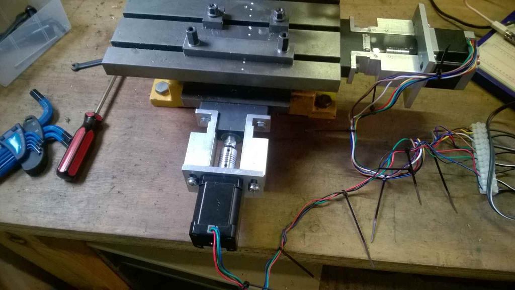
      One of my goals was to get my 2 Axis CNC conversion on my little mill finished.. I kind of managed this and it's working sort of, but I made the mistake of deciding to convert my program that drove it to Windows 10 (so I could run if from my phone). Don't ask my why. And don't ask me why I thought that Microsoft for once would have moved versions without totally reworking everything and requiring you to learn it all again.

      And my arduino code was flawed too

      Still it's going (of 5 days later than I expected) and I now await the next delay on my project with anticipation

      2 axis conversion.jpg

      (If you're wondering why the motors are different – I started off with a nema 17 then decided I wanted to use NEMA23 – with double ends for manual control. I've not got round to building the brackets for the second NEMA 23 – though I may try that on the Z axis next..)

      Advert
      #241395
      Neil Wyatt
      Moderator
        @neilwyatt

        Fitted the vice I got at Harrogate, it has a slot on the bottom a close fit for two 14mm blocks. Unfortunately the t-slots on my old-style X2 are 12.5mm. ish. Milled steps in them down to 12.5mm, a bit loose in the middle slot I will use most, but also fits the far slot. I will just have to remember to push the vice away from me when fitting it which is no great worry. I don't do anything heavy enough to shift the vice on the table.

        I then took the vice off again because I needed the tilting one to make some dovetail bars to fit on my scope mount, one for a small newtownian scope and little one for cameras (it can be llttle because it will only be used with my dual accessory bar).

        I made a note of the cuts used, but I'll post that on the Dore Westbury thread.

        Neil.

        #241398
        Anonymous
          Posted by Muzzer on 04/06/2016 15:06:41:

          Of course, you realise that this requires you to acquire a MIG / MAG machine. I find them much easier and quicker than MMA, not least because you can see what is going on and the wire feed takes care of itself. Slight downside is that you need a different gas (Argon-CO2 mixture for MAG / steel).

          Believe me I've been there! Even went to the local welding emporium to look over MIG welders a couple of years ago. Trouble is the decent ones were quite expensive. I get the impression that the cheap ones can have problems with the wire feed; I can't be **** with things that sort of work but aren't exactly right. The other issue is where would I put it? The TIG welder is already living in the hall and the kitchen is full.

          Andrew

          #241406
          Muzzer
          Participant
            @muzzer
            Posted by Andrew Johnston on 04/06/2016 17:46:41:

            The other issue is where would I put it? The TIG welder is already living in the hall and the kitchen is full.

            Andrew

            Mine is a second hand professional machine. As you say, those Xmas cracker ones are a royal pain – proper ones make the job so much easier.

            As for the space – sounds as if you need to do what I'm doing ie build a proper workshop!

            #241425
            Anonymous
              Posted by Muzzer on 04/06/2016 18:33:43:

              As for the space – sounds as if you need to do what I'm doing ie build a proper workshop!

              crying 2crying 2crying 2crying 2

              It's darn lucky you are 200 miles away, or I'd be squatting in the new workshop before the builders had left.

              Andrew

              #241546
              JasonB
              Moderator
                @jasonb

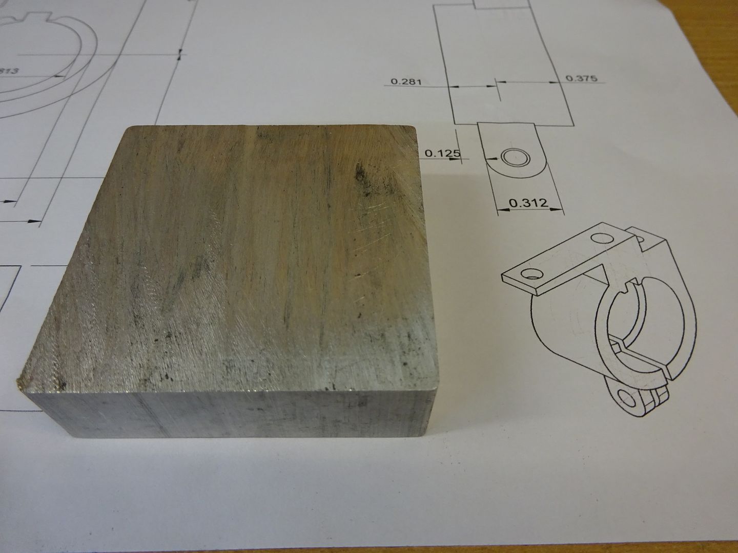
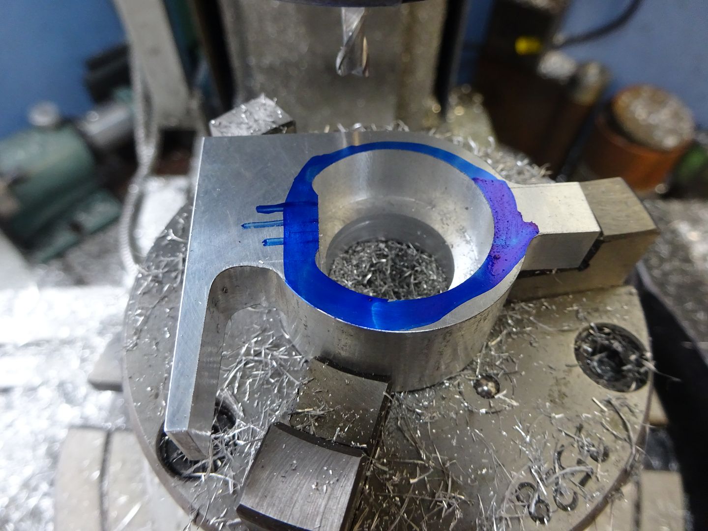
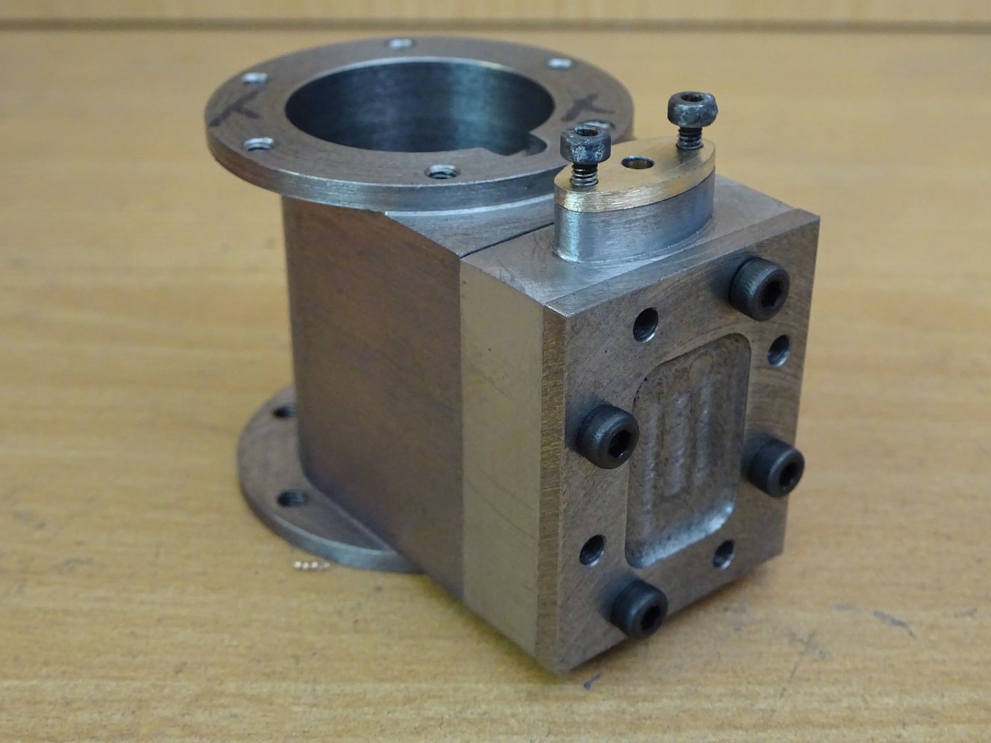
                On Friday evening I lopped of a bit of 2" square 6082 and thought I would see if there was one of these ignition brackets inside.

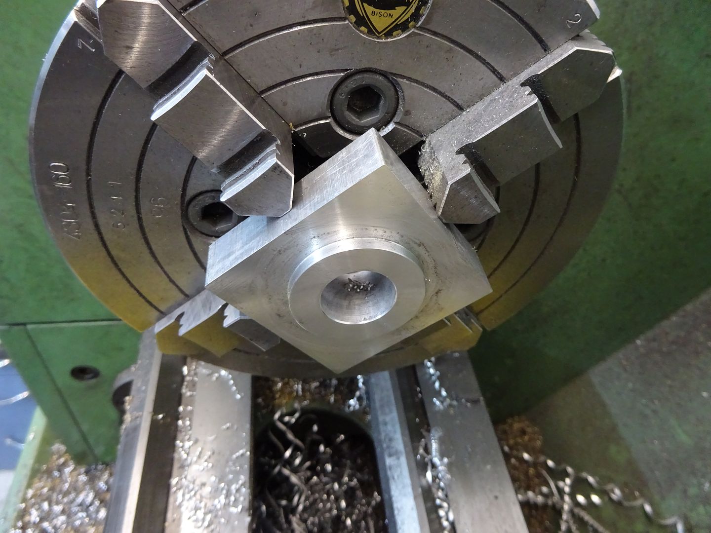
                Started with a bit of turning and bored the hole to fit the spigot on the crankcase

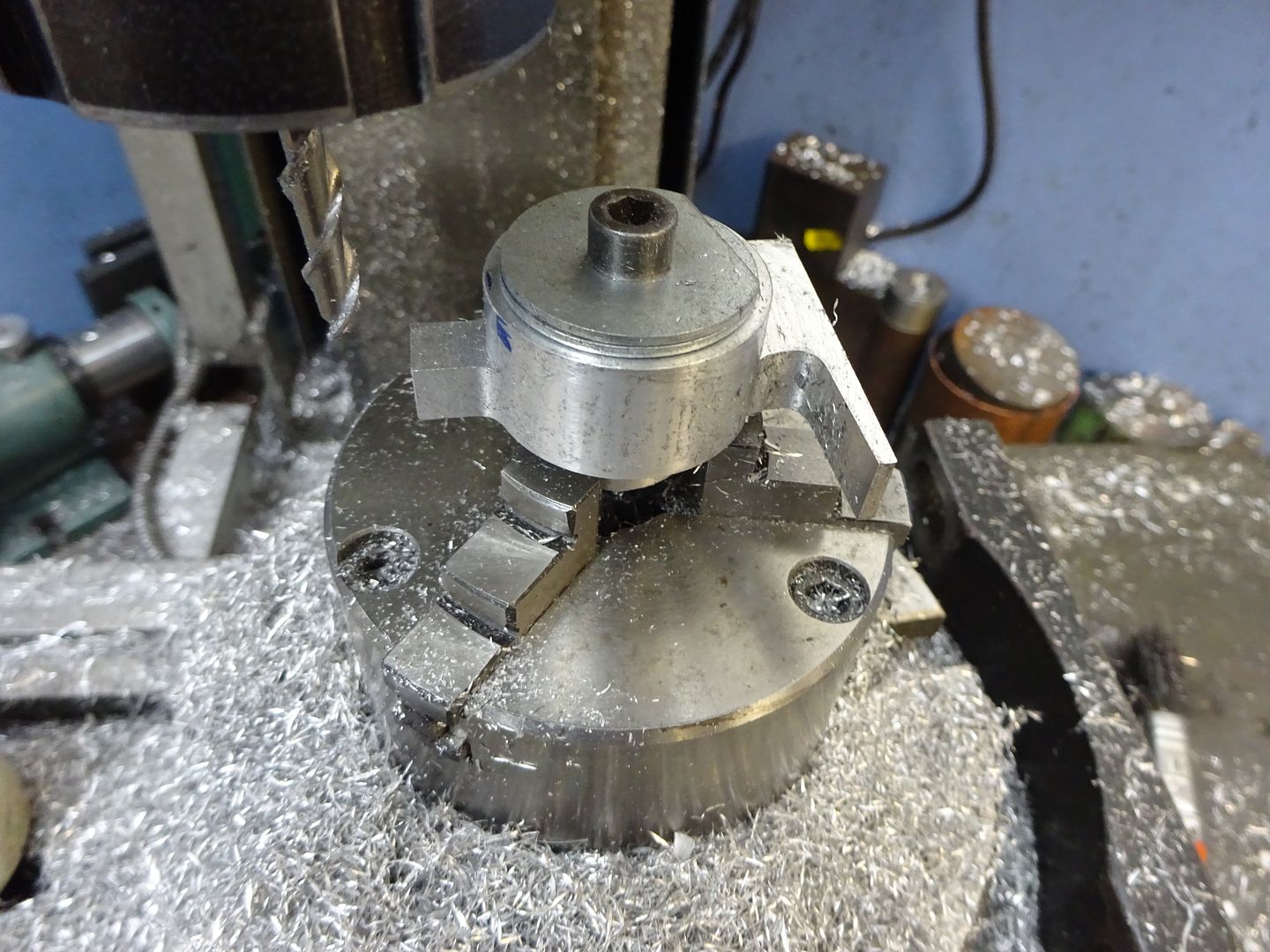
                Then with it mounted on the rotary table I went at it with one of Ketan's 6mm HSS bits for aluminium.

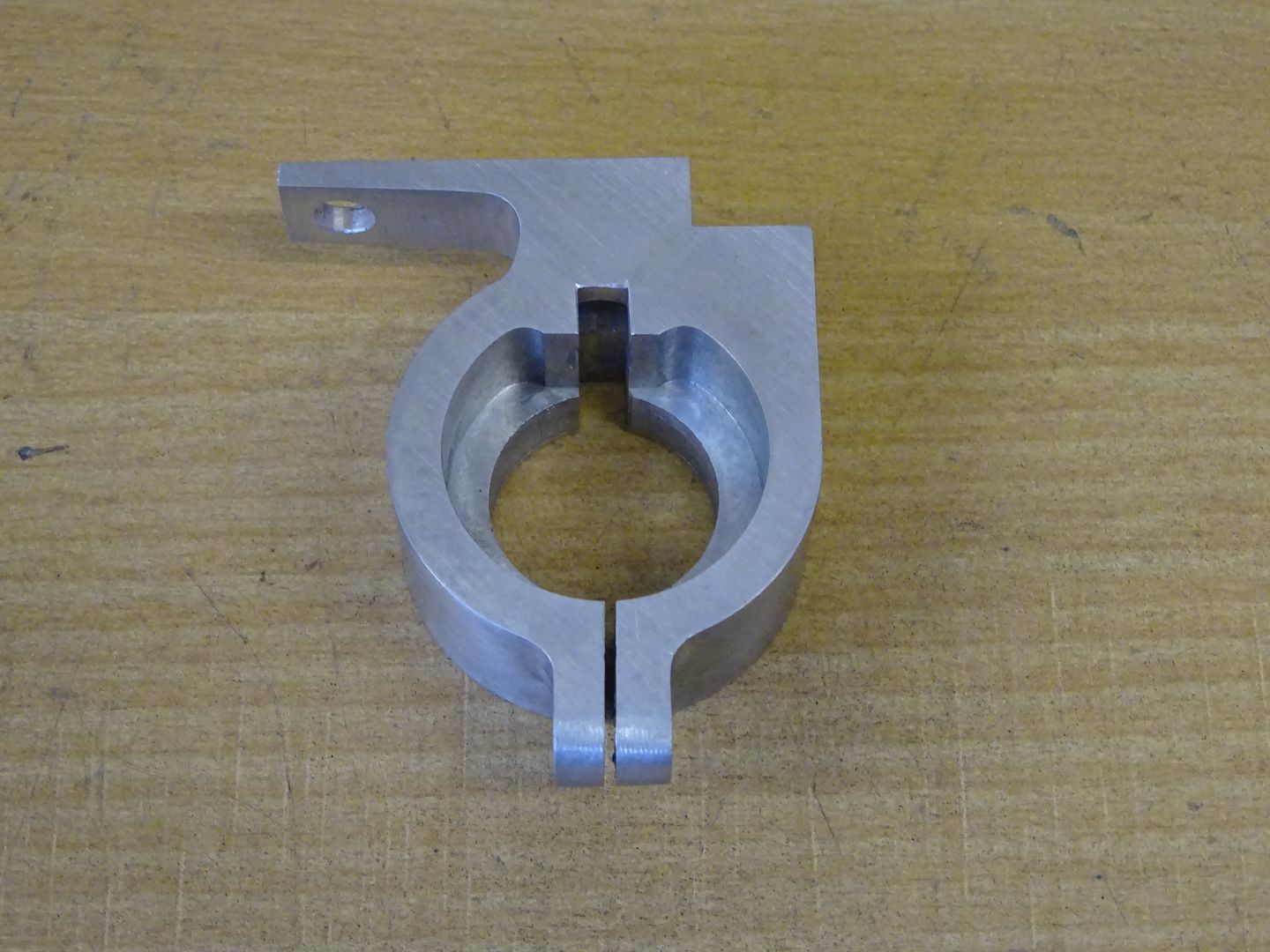
                Flipped it over and cut the shaped recess with a 5mm FC-3 cutter

                As I don't have a 5/32" broach in my collection I planed out the slot with a bit of 4mm HSS toolsteel using the lathe carrage .

                Add a few holes and a slot and thats another part off the list

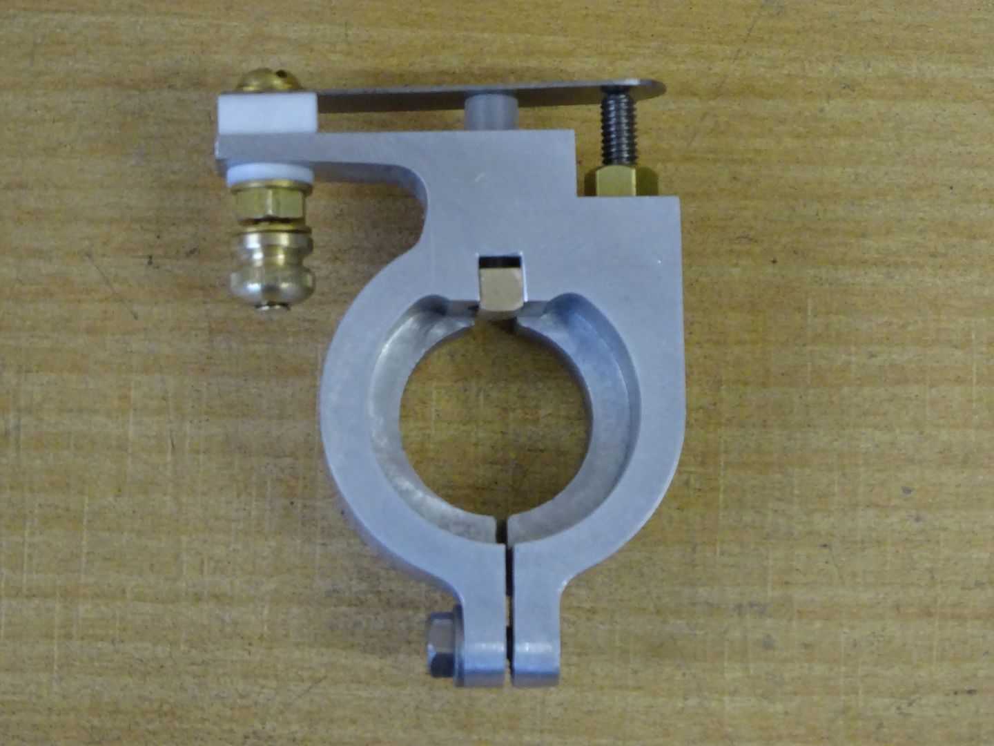
                This is it with a few more little bits added. A cam that fits onto a taper on the end of the crankshaft pushes the bronze block upwards, that inturn pushes a plunger that lifts the spring steel blade off the contact pin.

                J

                #242520
                Nicholas Farr
                Participant
                  @nicholasfarr14254

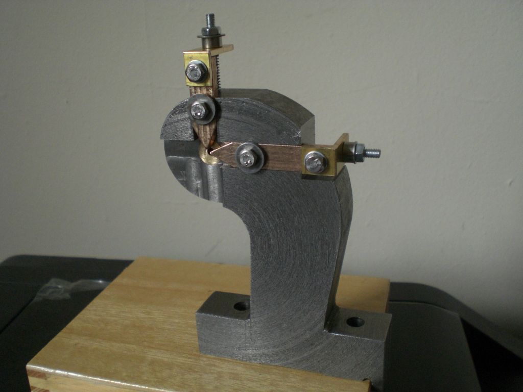
                  Hi, it's been awhile since I've been able to do anything more to my travelling steady. I did make a brass insert to fit into the hole at centre height and drilled it to a close fit to a rod that I wanted to turn down, however, although it did work, the portion that was reduced in diameter turned out to be tapered.

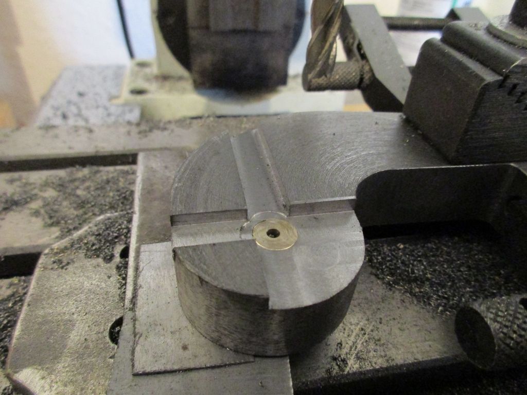
                  Having suspected that the original simple idea may not have worked, I employed my contingency plan. Firstly, two 8mm x 3mm channels were mill at right angles to each other, one is on the centre line on the vertical plain and the other is on the centre line on the horizontal plain.

                  img_0038 (1024x768).jpg

                  The bottom forward quarter from just above the brass insert was then milled away to a depth just below the two channels. A section at the back of the horizontal channel was then milled out to form a step the whole thickness of the steady and about 2mm below the bottom of the channel. (I forgot to take a photo of that, but it will be seen in a later photo)

                  Regards Nick.

                  #242524
                  Nicholas Farr
                  Participant
                    @nicholasfarr14254

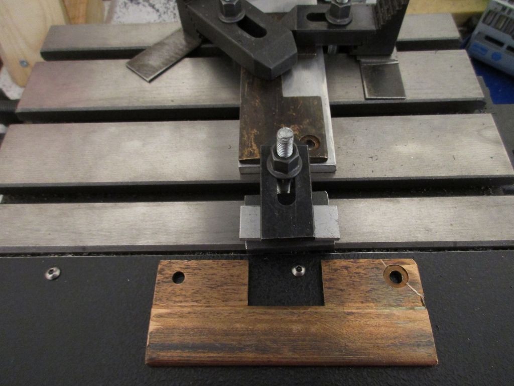
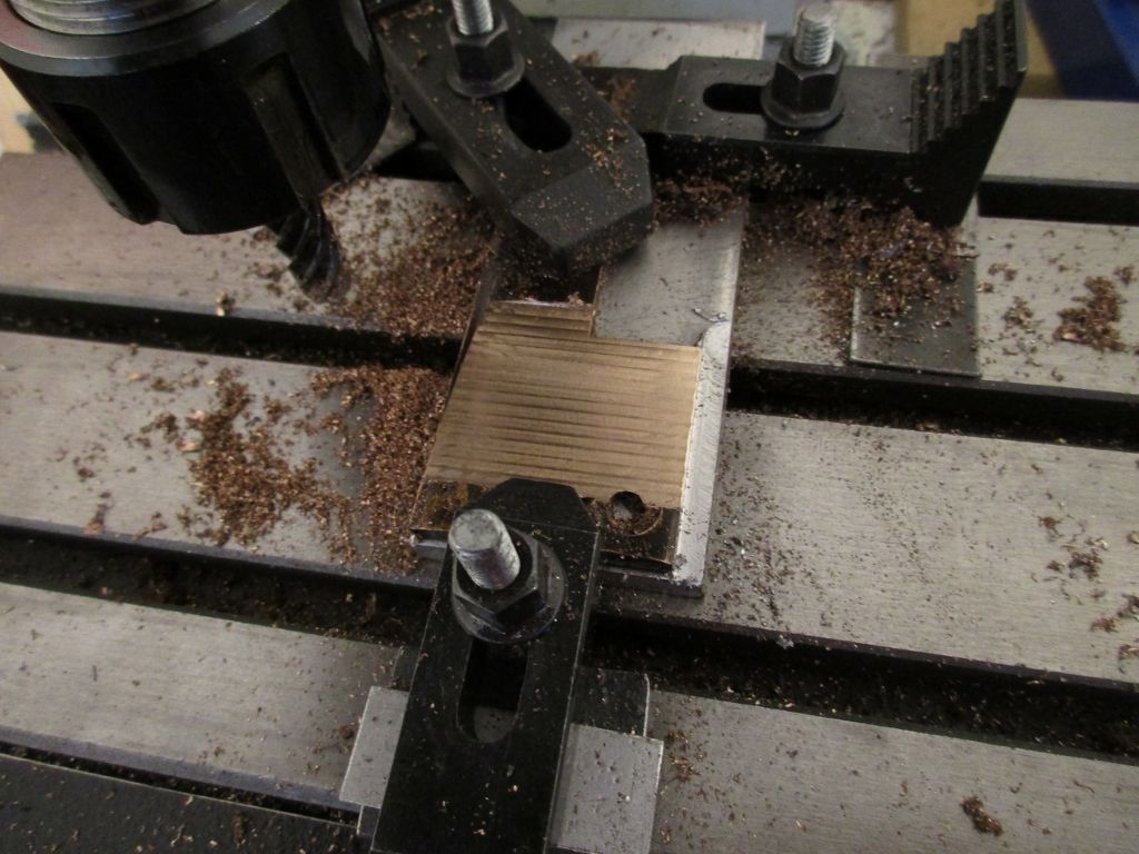
                    Hi, The next thing I did was to mill flat a worn bronze wear plate that I salvaged from a machine that a couple of workmates and myself did maintenance on for a customer earlier this year.

                    img_0075 (1024x768).jpg

                    Notice the sacrificial piece of aluminium that the bronze wear plate is clamped down onto.

                    img_0076 (1024x768).jpg

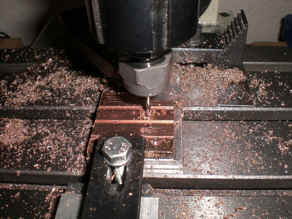
                    Two 8mm fingers were partially cut through with a 3mm end mill and a 6mm long x 3mm wide slot was milled close to one end on the centre line of each finger.

                    cimg2232 (1024x768).jpg

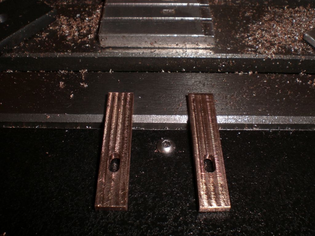
                    Once the slots were finished, the fingers were completely milled out.

                    cimg2234 (1024x768).jpg

                    The ends of the fingers near the slots were then hack-sawed and filed to a 60ish degree point, but leaving about 1mm of flat on the point end and one finger was reduce in length.

                    img_0077 (1024x768).jpg

                    Regards Nick.

                    #242684
                    JasonB
                    Moderator
                      @jasonb

                      I wanted to test out something on teh mill and rather than aimlessly turn perfectly good metal into swarf decided a better test would be to make something.

                      So made a start on the next engine, cut a bit of 8mm ali

                      And machined it into this.

                      Also milled a rough sawn block of iron into a square sided block then bored it out, who says cast iron produces dusty swarf?

                      #242727
                      Nicholas Farr
                      Participant
                        @nicholasfarr14254

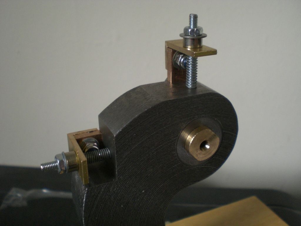
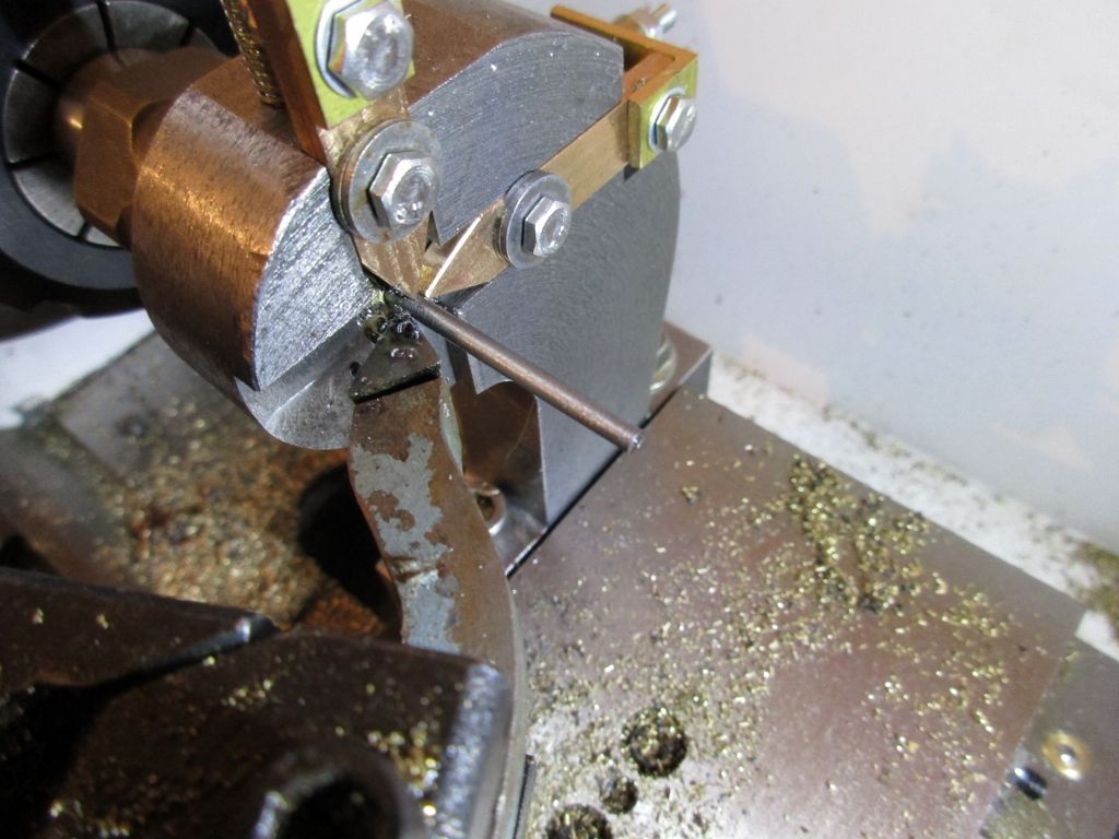
                        Hi, the next stage of my travelling steady was to attach a piece of brass angle 8mm long to each one. These were cut from a 3/4" x 3/4" x 3/32" section that I have and one leg of each piece was then cut down to 10mm, this leg was then drilled along with one of the fingers and were bolted together. A single 3mm hole was also drilled in the other leg of each angle, to correspond with M3 drilled and tapped holes in the top and back of the steady and on the centre line of the milled channels. Two M3 holes were also tapped in an appropriate position in the milled channels for the slots in the fingers. Threaded rod is used in the M3 holes in the top and back of the steady with a spring and these are used for the in/out adjustment of the fingers and M3 bolts and washers are used in the finger slots to nip them tight once adjusted.

                        cimg2235 (1024x768).jpg

                        cimg2236 (1024x768).jpg

                        Upon trying this setup, it was found to be able to reduce my 2.25mm diameter rod by 0.05mm with ease and parallel.

                        img_0078 (1024x768).jpg

                        I now have a successful travelling steady for small diameter rod for my Conquest lathe.

                        Regards Nick.

                        #242913
                        John Hinkley
                        Participant
                          @johnhinkley26699

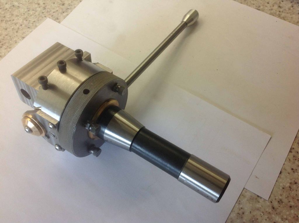
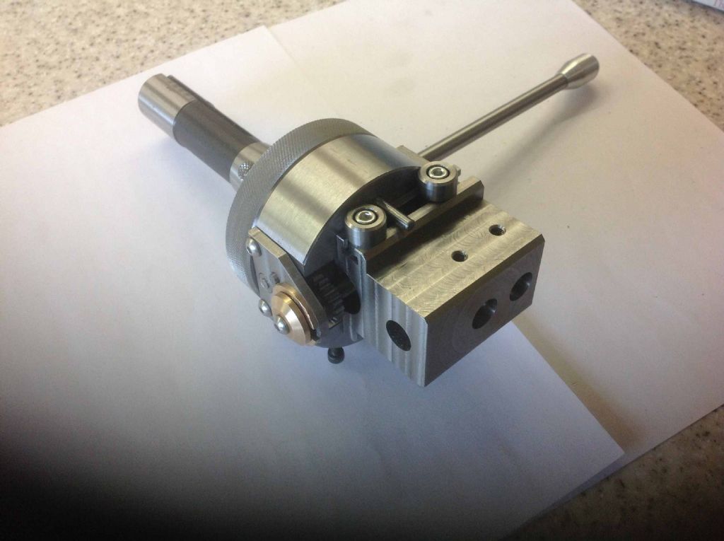
                          Now mostly recovered from my angiogram, I went back into the workshop to build up the boring/facing head. There's still some tweaking to do, but it works (under hand power). Just remains to try it on the mill – but that is for another day.

                          Finished at last!

                          And, flipped over …………..

                          Showing travel stops

                          More pictures of how I got to this stage are in my album "Modifying a Graham Meek design", if you're interested.

                          John

                          #243341
                          JasonB
                          Moderator
                            @jasonb

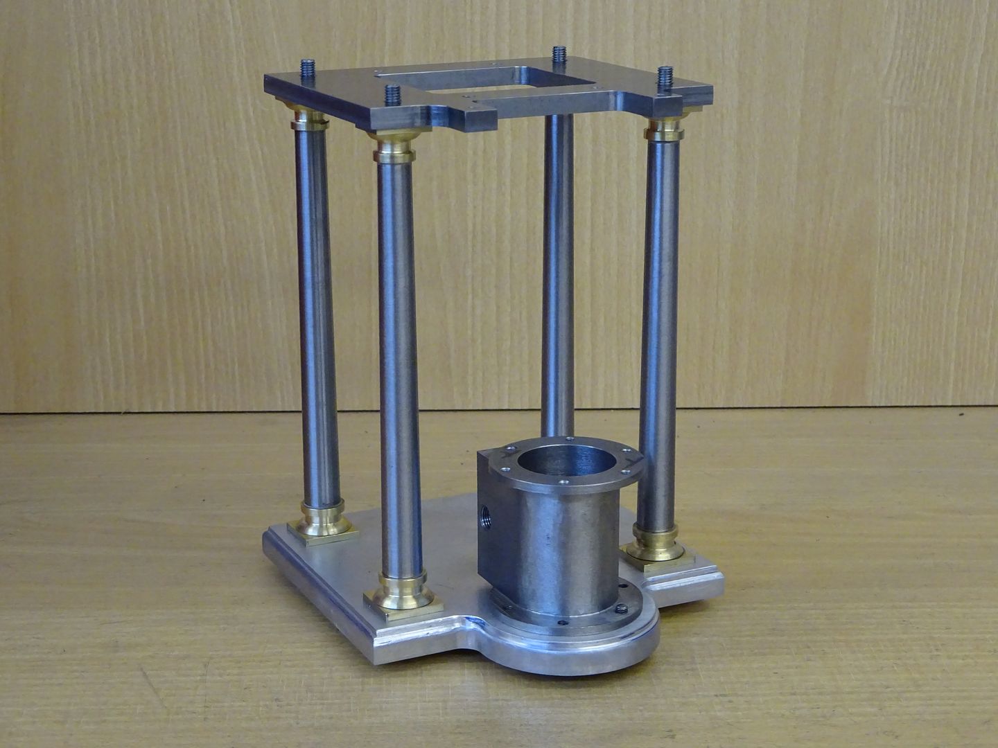
                            Between cutting the lawn, watching F1 qualifying and a bit of LeMans I managed to get a bit more done on the latest engine, well I did do a bit in the evenings last week toowink

                            #243343
                            Anonymous

                              Ah well, I was going to post about making a few miserable square head bolts this afternoon but I don't think I'll bother. sad

                              Andrew

                              #243380
                              JasonB
                              Moderator
                                @jasonb

                                Go on Andrew, always like to see what you have been upto with the Britan or as there were only a few was it not worth setting up for a batch?

                                #243417
                                Hopper
                                Participant
                                  @hopper
                                  Posted by Nicholas Farr on 14/06/2016 06:17:38:

                                  Hi, the next stage of my travelling steady was to attach a piece of brass angle 8mm long to each one. These were cut from a 3/4" x 3/4" x 3/32" section that I have and one leg of each piece was then cut down to 10mm, this leg was then drilled along with one of the fingers and were bolted together. A single 3mm hole was also drilled in the other leg of each angle, to correspond with M3 drilled and tapped holes in the top and back of the steady and on the centre line of the milled channels. Two M3 holes were also tapped in an appropriate position in the milled channels for the slots in the fingers. Threaded rod is used in the M3 holes in the top and back of the steady with a spring and these are used for the in/out adjustment of the fingers and M3 bolts and washers are used in the finger slots to nip them tight once adjusted.

                                  cimg2235 (1024x768).jpg

                                  cimg2236 (1024x768).jpg

                                  Upon trying this setup, it was found to be able to reduce my 2.25mm diameter rod by 0.05mm with ease and parallel.

                                  img_0078 (1024x768).jpg

                                  I now have a successful travelling steady for small diameter rod for my Conquest lathe.

                                  Regards Nick.

                                  Lovely looking bit piece of work there Nick!

                                  #243464
                                  Anonymous
                                    Posted by JasonB on 19/06/2016 07:27:07:

                                    ……always like to see what you have been upto with the Britan or as there were only a few was it not worth setting up for a batch?

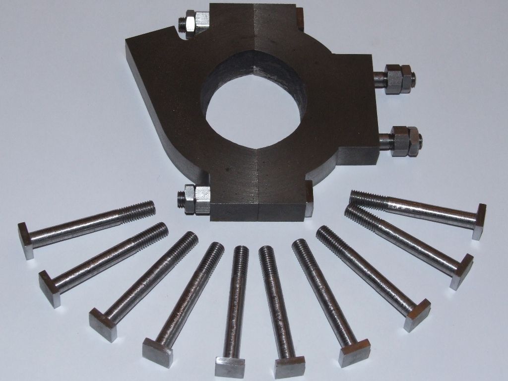
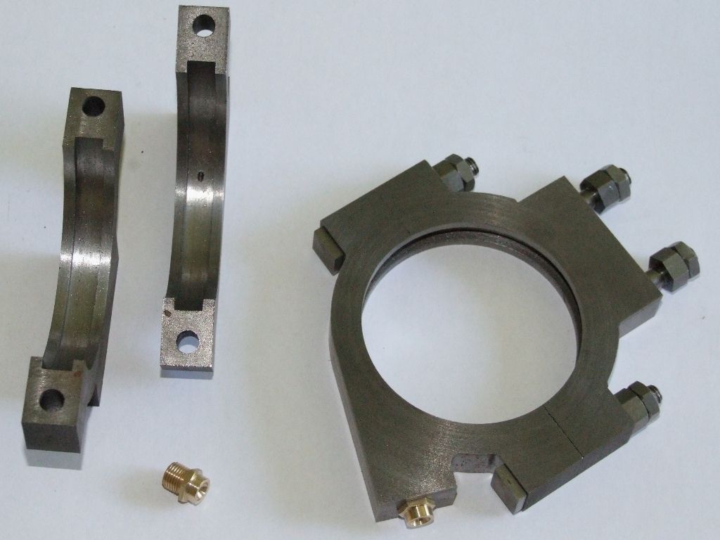
                                    Yes, I did use the Britan for most of the operations. However I used the Bridgeport to reduce the heads from 1/2" square. This was necessary due to a foul up in the position of the hole on the eccentric strap. If left at stock size the head would have been proud of the strap. I'm not really happy with the bolts, somehow they don't look right, I think the heads are too thin? But I'm not sure I've got the enthusiasm to make them again. Here are the bolts:

                                    square head bolts.jpg

                                    The nuts and studs were made ages ago, and I profiled the outside of the straps last week, on the CNC mill.

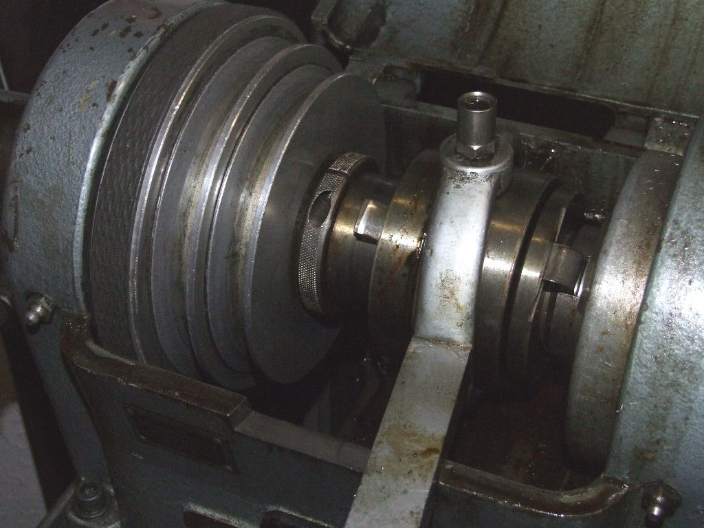
                                    I also had a screw failure on the Britan. sad When changing collets from 1/2" square to 1/4" round the screw that clamps the collar that sets the force required to operate the collet closer snapped. It doesn't stop one using the lathe, but will need to be replaced. I'm hoping I can get the broken bit out without having to dismantle the headstock:

                                    headstock.jpg

                                    The offending collar is the knurled one in the centre, just to the right of the pulleys.

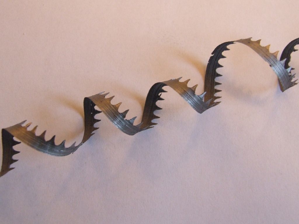
                                    On a more positive note the swarf that came off when reducing the 1/2" square stock to 1/4" diameter, in one pass, is rather pretty:

                                    square swarf.jpg

                                    Although it varies, the thickness is around 12 thou.

                                    At least I've cut the grass today before it rained, spent ages weeding, and cleared out the gutters sufficiently that I'm no longer embarrassed to call out the required gutter cleaning and repair company. thumbs up

                                    Andrew

                                    #243522
                                    JasonB
                                    Moderator
                                      @jasonb

                                      Thanks Andrew, I won't feel so guilty about posting anymore progress reports now.

                                      The fitted bolts on the Fowler eccentrics have their heads approx the same height as the full nut on the other end which seem to look OK. They are also a "D" shape rather than your square ones. The Minnie has square ones more in proportion to yours being approx 1/16" thick with 3/32" hight full nuts

                                      #243573
                                      Muzzer
                                      Participant
                                        @muzzer

                                        img_0405.jpg

                                        This is a full size Burrell where I used to work. I assume it's fairly original. The lock nuts look good but I must agree the square heads seem proportionately thicker here.

                                        Edited By JasonB on 20/06/2016 17:54:52

                                        #243616
                                        Anonymous
                                          Posted by JasonB on 20/06/2016 11:00:26:

                                          Thanks Andrew, I won't feel so guilty about posting anymore progress reports now.

                                          That's ok, I don't mind being the guy showing how it shouldn't be done. embarrassed

                                          Andrew

                                          #243620
                                          Anonymous

                                            Muzzer, thanks for the picture. I've been all round the ****** houses with the bolts today. Having looked at some pictures of a model Burrell it used hex head bolts, so I decided to bin the square head bolts and make some hex head ones. An advantage is that the hex head will clear the oiling lug so the bolts can be fitted the correct way round, ie, nuts towards the rods. Then I had a closer look at the pictures I took in Burrell museum and the bolts definitely look square headed. This is confirmed by the much clearer picture from Muzzer. Then I tried a square head bolt and blow me down, the darn thing fits the correct way round. So the upshot is that I'm going to stick with the square head bolts and fit them the correct way round. I will take the sharp corners off the heads with some wet 'n' dry. Who'd have thought a simple bolt could cause so much trouble; no wonder the build is taking me years.

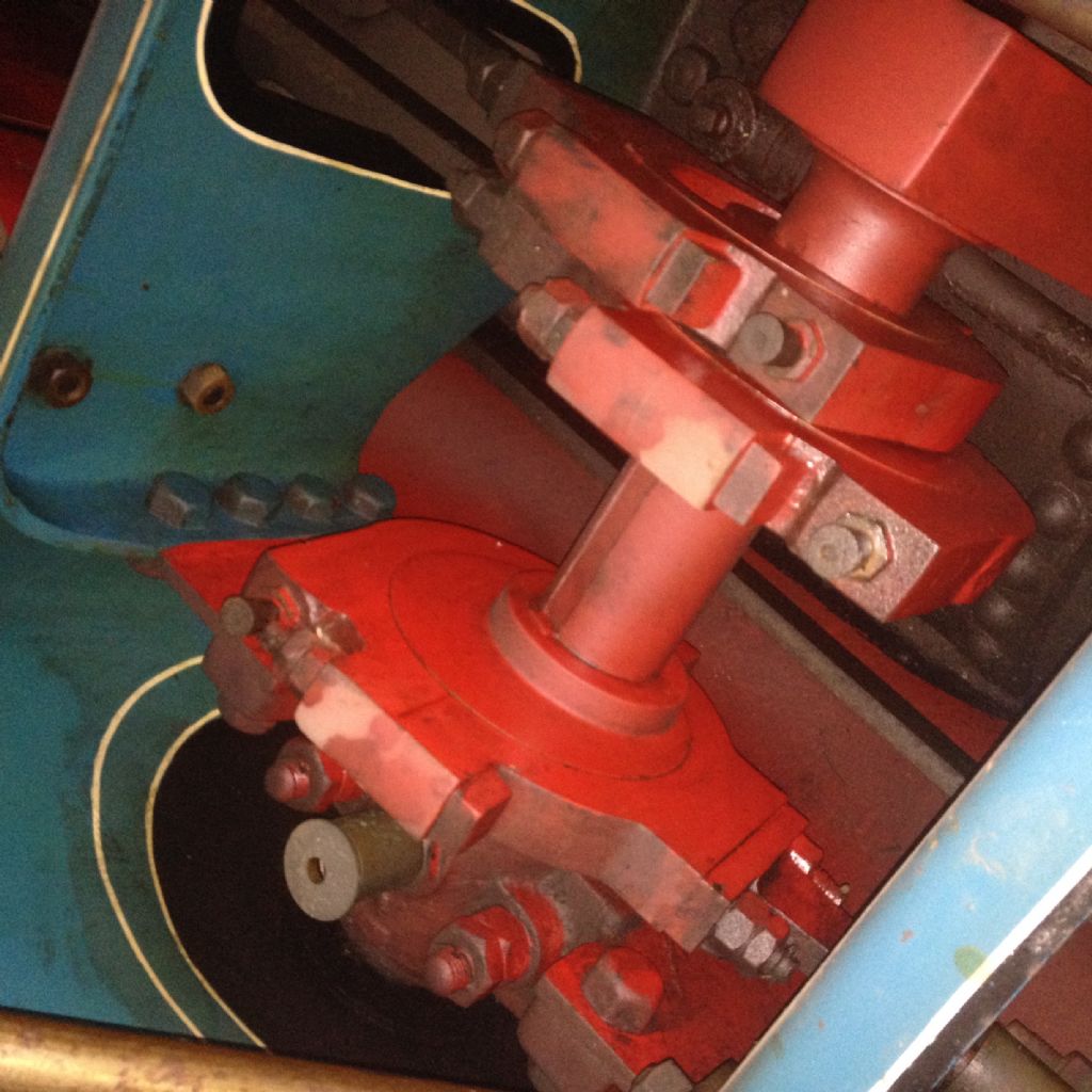
                                            I also noticed in my picture of the Burrell, and shown above, that the straps are not flat on the tops of the bolt holes but curved. It's easy to model this in 3D CAD, radius 2", but it's going to be tricky holding the straps to machine them.

                                            Muzzer: There's an inconsistency in your picture, the eccentric strap bolts for the water pump (at the bottom) are the wrong way round. Some-one has b*****ed about with 'em. wink 2

                                            I've removed the broken screw from the Britan without too much difficult, and no naughty words. The broken part measures 0.205" diameter and is as near as darn it 28tpi. So I'm 99.99% sure it's 1BA. I don't think I've ever used 1BA before, so I'll have to order some.

                                            Andrew

                                            #243638
                                            JasonB
                                            Moderator
                                              @jasonb
                                              Posted by Andrew Johnston on 20/06/2016 22:36:08:

                                              I also noticed in my picture of the Burrell, and shown above, that the straps are not flat on the tops of the bolt holes but curved. It's easy to model this in 3D CAD, radius 2", but it's going to be tricky holding the straps to machine them.

                                              Bench vice and a file? or at the opposite end of the scale you could make a custom cutter for the horz millwink 2

                                              Edited By JasonB on 21/06/2016 07:24:45

                                              #243650
                                              Anonymous

                                                My filing probably isn't that good. I have radius cutters for the horizontal mill, but they're not that large, although I could make one. The 2" radius was carefully chosen, as the straps are 4" wide. So in theory it's a simple turning job, albeit an interrupted cut. The issue is how to hold the strap without spending longer on making the jig than cutting the parts. I have an idea of how to do it, involving a lump of hot rolled steel.

                                                Andrew

                                                #243682
                                                JasonB
                                                Moderator
                                                  @jasonb

                                                  Vice mounted on top of a rotary table may be easier and just mill the sides. Or block of metal drilled & tapped at the bolt spacing ontop of the R/T.

                                                  Boring head set to cut externally if you don't want to lift the R/T onto the mill.

                                                  Edited By JasonB on 21/06/2016 12:26:09

                                                  #244256
                                                  JasonB
                                                  Moderator
                                                    @jasonb

                                                    So Andrew did you get the edges of the eccentric straps rounded off this weekend?

                                                    I got the valve chest and cover for the latest engine done last Sunday, cap heads are only temporary.

                                                    Managed to get a few hours in during the week and yesterday and have progressed whats on top of the entablature, was out most of today so no progress just a clean up of the workshop first thing.

                                                    I won't get much done next weekend as I'm at the Guildford show, anyone who is going come and say hello, I will have about 4 engines in the tent and should be there most of Saturday and Sunday afternoon, hopefully won't be as muddy as Glastonburycrook

                                                    J

                                                    Edited By JasonB on 26/06/2016 19:30:57

                                                    #244967
                                                    Anonymous
                                                      Posted by JasonB on 26/06/2016 19:30:08:

                                                      So Andrew did you get the edges of the eccentric straps rounded off this weekend?

                                                      Nope, 'fraid not; in fact not a great weekend all round. sad

                                                      However, having just finished the oilers, rounding the edges is the last operation on the todo list:

                                                      eccentric strap oiler.jpg

                                                      Andrew

                                                    Viewing 25 posts - 276 through 300 (of 457 total)
                                                    • Please log in to reply to this topic. Registering is free and easy using the links on the menu at the top of this page.

                                                    Advert

                                                    Latest Replies

                                                    Viewing 25 topics - 1 through 25 (of 25 total)
                                                    Viewing 25 topics - 1 through 25 (of 25 total)

                                                    View full reply list.

                                                    Advert

                                                    Newsletter Sign-up