The Workshop Progress Thread (2016)

Advert

The Workshop Progress Thread (2016)

Home Forums Work In Progress and completed items The Workshop Progress Thread (2016)

Viewing 25 posts - 251 through 275 (of 457 total)
  • Author
    Posts
  • #238254
    Zebethyal
    Participant
      @zebethyal

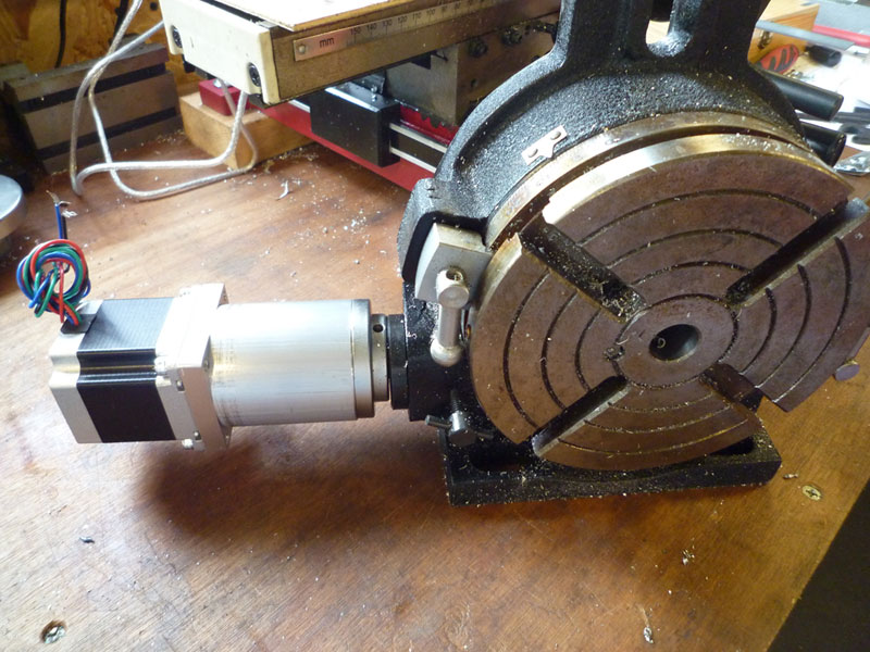
      I have been building a Division Controller for my Vertex HV6 rotary table (an alternative to the Division Master).

      The electronics are based on a 2007 design by Steve Ward (Kwackers on CNCZone), he makes the firmware available for free on his website.

      I used a reduced version of his design for my implementation which I built on a double sided perfboard.

      Total cost for all the parts was about £5.00, the PIC18F452 microcontroller was ordered as a free sample from Microchip.

      I will use my 3D printer to make an enclosure for it, the enclosure will also contain a 19v laptop power supply, a DC-DC buck converter to produce the 5v line for the controller and also the stepper driver.

      The stepper driver is a PMinMO design that uses a Toshiba 6560AHQ driver, I had a bunch of boards made up by IteadStudio (10 for $9.99).

      (I will leave out the voltage regulator on the one I put together for this project), total parts cost is under £5.00

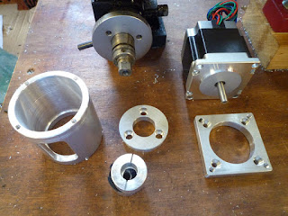
      I have just finished making the parts for the adapter

      Just need to finalise my enclosure design and print it out along with another stepper cover like the ones I have made for the CNC conversion of my mini mill

      Edited By Timothy Moores on 11/05/2016 09:40:41

      Advert
      #238259
      Bob Rodgerson
      Participant
        @bobrodgerson97362

        Old Metaller

        the quote "Rod- you can't beat having beautiful tools" reminds me of a story related to me many years ago by an Irish lad who was working as a teacher somewhere in the Caribbean. He was involved in a motorcycle accident in which he went over the handlebars of the bike, severely battered and bruised he was taken off to the local hospital.

        This lad had a reputation for having a wild sense of humour which he put to the test during the doctors rounds later that morning when a very attractive junior lady doctor was visiting the patients. I should add though bruised around the top of his legs where he hit the handlebars, thankfully his wedding tackle was unharmed. As the young doctor approached his bed he started moaning and groaning as if in agony so the doctor came to see what was wrong; "Can you look my Willie please" says he. The doctor somewhat worried about his apparent worsening decided to have a look so she slid back the blanket and proceeded to hold his willie up and inspect same.

        She declared, "Theres nothing wrong with it"

        He Replied " I know it's a beaut isn't it" several of the visiting party were laughing fit to bust for a long time afterwards and the young doctor went away very red faced.

        #238298
        Muzzer
        Participant
          @muzzer
          Posted by Timothy Moores on 11/05/2016 09:40:05:

          The stepper driver is a PMinMO design that uses a Toshiba 6560AHQ driver, I had a bunch of boards made up by IteadStudio (10 for $9.99).

          Not familiar with PMinMo or IteadStudio. Presumably IteadStudio is this place. PMinMo.com seems to be no more.

          How does it work – I assume you upload the PCB files to IteadStudio (which you found somewhere) and they send you them in the post. Not a bad price.

          Is there anywhere that will kit all the parts for you (for either or both of the controller and driver) or did you have to scout around for them all? Steve Ward only seems to offer the controller without the display unless you buy it preassembled and tested.

          Murray

          #238309
          Zebethyal
          Participant
            @zebethyal

            PMinMO, is as you say, unfortunately no more, the owner closed down due to health issues, although the site can still be accessed via wayback machine, this is the link for the above stepper driver.

            If you have a circuit you (or someone else) has designed and you can export the relevant gerber files (there are well documented processes for doing this with Eagle), you then upload the gerber files for the relevant layers to IteadStudio and select what type of board you want. The stepper boards were under 5cm square so were $9.99 for 10 boards, I had some Sanguinololu boards made (about 5x10cm) for use on other 3d printers I intend to build – 10 boards for $19.99.

            I already had most of the components for the division controller, although to be fair for my implementation it was 8 resistors, 1 variable resistor, 16 buttons (and caps) a screen, a pcb, a microcontroller and a resonator.

            The screen (£2.86), pcb (£1.39), 12mm tactile buttons (£1.39 for 50) and caps (£1.99 for 140), all ordered from ebay, MCU (free) from Microchip, the other components are 7 x 10K resistors, 1 x 800 ohm resistor for the LCD backlight, a 10K variable resistor for LCD contrast and a 10MHz resonator, all of which I already had, but are pennies to buy even individually.

            Steve does also supply PDF files for etching your own boards (if you download the zip file), his original thread on CNCZone is here, by blog entry for the electronics build is here (although it does not say much more than I have already posted on this site).

            My board was made with stripped lengts of wire from solid core cat 5 network cable using this layout (I drew in DIYLC) as a wiring guide:

            #238345
            Howi
            Participant
              @howi

              I got a kit of parts from Steve Ward, got a good quality stepper driver from eBay for a fiver ( uses latest chips), plus other bits from eBay inc stepper motor.

              Works really well, very powerful on 72 to 1 reduction ratio of my RT from Amadeal.

              Much better than counting holes and turns, with my memory I would just end up with a pile of scrap metal.

              Don't forget that if your driver board has open collector outputs one side needs grounding ( how do I know?)

              #238350
              Muzzer
              Participant
                @muzzer

                A tempting project for me to tackle in the indoor / armchair workshop, although there would still be the matter of the coupling etc at some later date. Thanks for all the info.

                #238689
                JasonB
                Moderator
                  @jasonb

                  Over the last week or so I have been converting a bit of 1.5" dia 2014 (HE15) bar into a large pile of swarf but did manage to leave enough solid metal to make this conrod.

                  Also finished off the piston by machining the profiled top, I worked out the offsets in Alibre and just let the DRO do the rest. 10mm rougher for the steps and a tapered 3-flute cutter with radiused corner for the "notch"

                  J

                  PS. I'm hoping this will be incentive for Nick_G to get his finger out and finish his Hoglet pistons & conrodssmile p


                  Edited By JasonB on 14/05/2016 20:30:37

                  #238695
                  NJH
                  Participant
                    @njh

                    Bob

                    He Replied " I know it's a beaut isn't it" several of the visiting party were laughing fit to bust for a long time afterwards and the young doctor went away very red faced."

                    I trust the she added a strong laxative to his daily medication!

                    Norman

                    #239488
                    John Hinkley
                    Participant
                      @johnhinkley26699

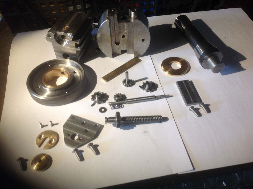
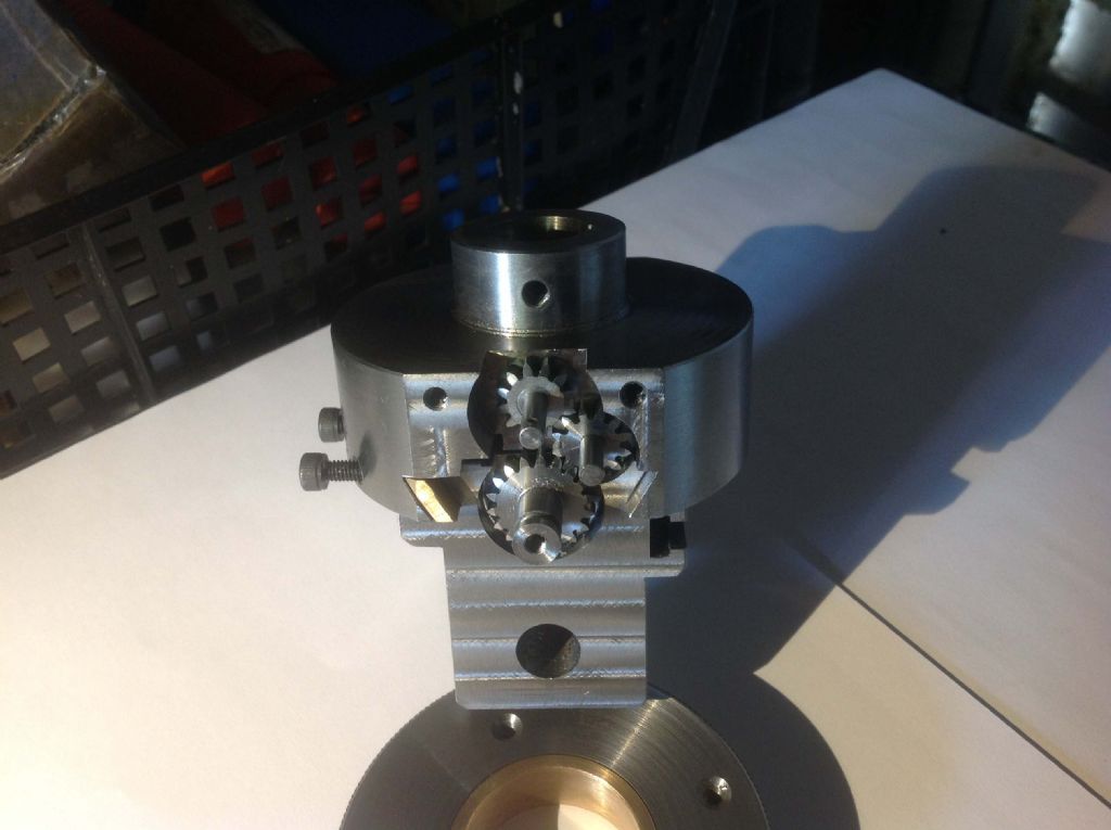
                      After a bit of a lull due to illness, I've been back in the 'shop to carry on with the boring/facing head. Did some lathery and trial fitting of various bits. Looks like I need to tweak the length of the driving pins a shade:

                      Collection of parts nearly complete Gear train trial assembly

                      Off on holiday for week now, so yet another delay! Still, I got David Gingery's book on making a shaper for my birthday (thanks, me!) so I'll come back enthused to make one of those, maybe.

                      John

                      #239504
                      duncan webster 1
                      Participant
                        @duncanwebster1

                        Loctited the wheels onto my latest loco, fit the rods and it all still goes round. Yippee. This is a significant milestone as there are a lot of potential pitfalls along the way.

                        #239505
                        Anonymous
                          Posted by JasonB on 14/05/2016 20:29:59:

                          Over the last week or so I have been converting a bit of 1.5" dia 2014 (HE15) bar into a large pile of swarf but did manage to leave enough solid metal to make this conrod.

                          Jason: How do you get the 'satin' finish on the conrod? Elbow grease or some sort of shot or bead blasting?

                          Andrew

                          #239515
                          JasonB
                          Moderator
                            @jasonb

                            I would like to have bead blasting facilities then I could make my engines look like Ramon's. Alas its elbow grease, 150 emery – I have a roll that looses its grit very quickly so gives a nice fine finish. This was followed up with a grey Scotchbrite pad.

                            I could go a bit finer with Garryflex but as it is going inside a crankcase don't see much point in further work. If it was external then maybe I would use that.

                            J

                            #239660
                            MW
                            Participant
                              @mw27036

                              I just had a very unexpected job to do for my lathe when attempting to turn a number of collets, my lead screw clutch on a Clarke CL430 finally gave out. The horrible grinding sound of metal indicated to me i had no choice but to take apart the clutch and gear train.

                              The culprit was the main drive bush which had completely disintegrated from cast monkey metal. Luckily i can use the lathe without the gear train operable so i was able to copy the old component in stainless. Had to painstakingly slowly mill a hex socket into the drive bush.

                              After alot of trial and error with different fits, pins and circlips i've got it back in once piece and it's healthy again. I couldn't believe such a crucial component was made out of bad metal.

                              Michael W

                              #240884
                              JasonB
                              Moderator
                                @jasonb

                                With the Lightweight comming together something was needed to stop it falling over so I thought I'd better make the stand.

                                Rather than cut into a good bit of plate for the base flange I tacked a few offcuts together and that saved having to cut a hole in the middle.

                                Cut and welded some 3mm sheet for the main box, the camera has mucked up the perspective but the sides do actually taper in towards the top to give it the look of the draft angle from the original casting.

                                Joined the two together from the inside which made cleaning up easier

                                Bit of milling

                                Followed by drilling, filling and fettling

                                Finally painting

                                #240891
                                Jeff Dayman
                                Participant
                                  @jeffdayman43397

                                  Out STAND ing! well done as usual Jason. JD

                                  #240910
                                  kevin beevers
                                  Participant
                                    @kevinbeevers61752

                                    its good to see people useing up offcuts and making something that you would think you bought it from a shop nice job

                                    #240971
                                    Ian S C
                                    Participant
                                      @iansc

                                      The crankcase for my "Ross Yoke" Stirling Engine was made by welding some cleaned up scrap steel. Ian S C

                                      #241265
                                      Hopper
                                      Participant
                                        @hopper

                                        Bit of (slow) progress on the fabricated versatile dividing head:

                                        Got the threaded rings made up, overarm and tailstock made up and all the little twiddly bits, including those very twiddly little tailstock locking ball-handled twidllers. One more to go on the main spindle lock.

                                        The ball handled twiddlers finished up slightly longer than GHT's original plans, by exactly the width of my parting tool blade. Fancy that!

                                        Gotta love Nikon cameras. It's only a little point and shoot but the glass is so good it does a great job of picking out every little emery paper scratch on what in real life looks like a nicely polished finish. That's my excuse and I'm sticking to it. (Well, it's better than "deliberate mistake" innit?)

                                        #241315
                                        Anonymous

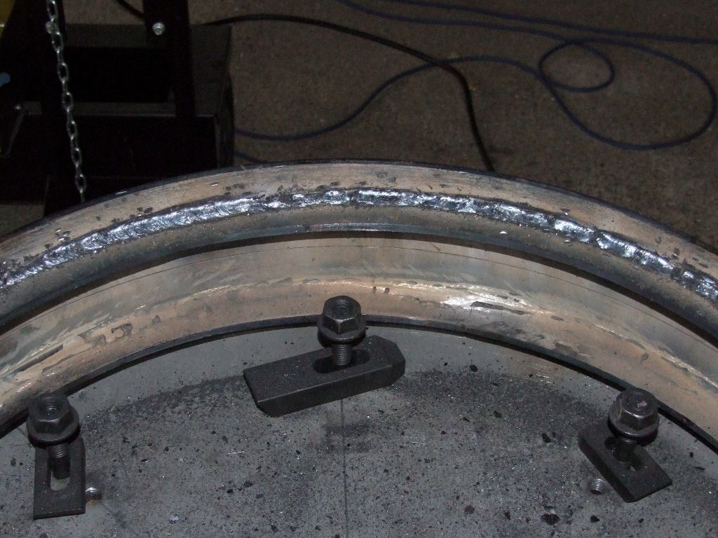
                                          My arc welding is improving, relatively speaking that is; another rear wheel rim and T-rings welded, three down one to go:

                                          welding - rear wheel rim.jpg

                                          Once I've finished I'll be able to start again and do it properly second time around. thumbs up

                                          Andrew

                                          #241326
                                          Muzzer
                                          Participant
                                            @muzzer
                                            Posted by Andrew Johnston on 03/06/2016 19:10:36:

                                            Once I've finished I'll be able to start again and do it properly second time around. thumbs up

                                            Indeed, the old story. I've certainly seen a lot worse in my workshop! Looking good to me from where I'm sitting.

                                            What's responsible for it – a stick welder or a TIG / stick inverter? The actual rods used can make a big difference too.

                                            #241344
                                            Nicholas Farr
                                            Participant
                                              @nicholasfarr14254

                                              Hi Andrew, I agree with Muzzer, look pretty reasonable to me. I'm guessing you are using stick electrodes.

                                              Regards Nick.

                                              #241353
                                              michael darby
                                              Participant
                                                @michaeldarby61557

                                                For a better finish, try iron powder electrodes they will give a smoother finish with less dressing needed Try esab femax 33.80

                                                #241362
                                                Neil Wyatt
                                                Moderator
                                                  @neilwyatt

                                                  Better than my Arc welding (not saying much…)

                                                  #241377
                                                  Anonymous
                                                    Posted by Muzzer on 03/06/2016 21:04:27:

                                                    What's responsible for it – a stick welder or a TIG / stick inverter? The actual rods used can make a big difference too.

                                                    I'm using the MMA function on a DC/AC TIG welder. So the arc should be pretty stable compared to a 'buzz' box. I'm running 3.2mm rods at 110A, at which point the welder still has a 100% duty cycle. Just a pity about the defective operator. sad

                                                    Before I started welding the T-rings into the rims I did some experiments with MMA and TIG, but thought that TIG welding on 1/4" plate was a bit OTT. I seemed to need quite a high current for the TIG to get a proper fillet and it was slow.

                                                    Michael: Thanks for the tip; I'll need to buy some more rods to finish the job. A long time ago I bought some Hilco rods, which I didn't seem to get on with. The local welding emporium recommended rods by Oerlikon. Having finished those I reverted to the old Hilco rods to finish the welding session. And what do you know; the welding seemed to go a lot better with neater welds. I keep my welding rods in the airing cupboard to prevent moisture absorption. I've obviously got a lot to learn.

                                                    At least I can say it's all my own work.

                                                    Andrew

                                                    #241388
                                                    Muzzer
                                                    Participant
                                                      @muzzer

                                                      Yes, TIG would have taken forever, cost an arm and 10 legs and you would have been frazzled by the end. It's also pretty awkward when you are trying to fit everything into a confined space – torch, filler, hands, head and mask. Certainly worth trying a few rods out at some point – surprising how different they can be.

                                                      Of course, you realise that this requires you to acquire a MIG / MAG machine. I find them much easier and quicker than MMA, not least because you can see what is going on and the wire feed takes care of itself. Slight downside is that you need a different gas (Argon-CO2 mixture for MAG / steel).

                                                      Murray

                                                    Viewing 25 posts - 251 through 275 (of 457 total)
                                                    • Please log in to reply to this topic. Registering is free and easy using the links on the menu at the top of this page.

                                                    Advert

                                                    Latest Replies

                                                    Viewing 25 topics - 1 through 25 (of 25 total)
                                                    Viewing 25 topics - 1 through 25 (of 25 total)

                                                    View full reply list.

                                                    Advert

                                                    Newsletter Sign-up