The TurboCAD Problem – A Further Question

Advert

The TurboCAD Problem – A Further Question

Home Forums CAD – Technical drawing & design The TurboCAD Problem – A Further Question

  • This topic has 10 replies, 6 voices, and was last updated 7 May 2021 at 12:18 by Nigel Graham 2.
Viewing 11 posts - 1 through 11 (of 11 total)
  • Author
    Posts
  • #543251
    Nigel Graham 2
    Participant
      @nigelgraham2

      With thanks to those who helped me solve why I could not copy areas of one drawing to another, and the source drawing also freezing, I have a more detailed question.

      The same [Not Responding] problem arose briefly yesterday, with my large general-arrangement drawing.

      It has several layers in different colours, but overall is only 4 orthographic elevations with little detail. I have been careful not to create the hidden stacks that crippled the other drawing.

      It is not a rendered 3D picture – mathematically I'd have thought my wagon GA simpler than Jason's 3D image of his engine irrespective of different make of software; but it may hold more elements.

      '

      So my question…

      Is there a definite limit to the size and complexity of a drawing that TurboCAD and the computer can handle?

      Or is the problem caused by keeping all the Layers visible when working on any one part of the drawing?

      Or something else again?

      (If just drawing size, I don't understand how it copes with producing the beautiful pictures in the TC Users' Forum.)

      '

      = = =

      Incidentally, I said I would find making a 3D image of the wagon, impossible.

      Well, that's not just a guess. I did try it.

      I drew the two long chassis rails, parallel, but without the cross-section tapers of their hot-rolled steel material.

      Next, the three cross-members shortened from copies of the above.

      Plus one temporarily copied to the front of the chassis for locating further components. That was to simplify the co-ordinate calculations as the image's screen co-ordinates are random, and the 3D sizing and moving tools often have unexpected and sometimes irreversible effects.

      Then the two short, parallel channels for the narrowed front section.

      That was it!

      My barrier was the converging section linking the two parallel sections.

      The physical, full lengths of the channels were fairly easily shaped using a rail-bender to chalk-lines on the floor, and tape-measure. The drawing's convergent parts lie at angles to the X and Y axes and though very easy to draw manually, I found them too difficult in CAD.

      Advert
      #21346
      Nigel Graham 2
      Participant
        @nigelgraham2
        #543257
        JasonB
        Moderator
          @jasonb

          Computer is usually the limiting factor both memory and graphic card need to be able to handle the file.

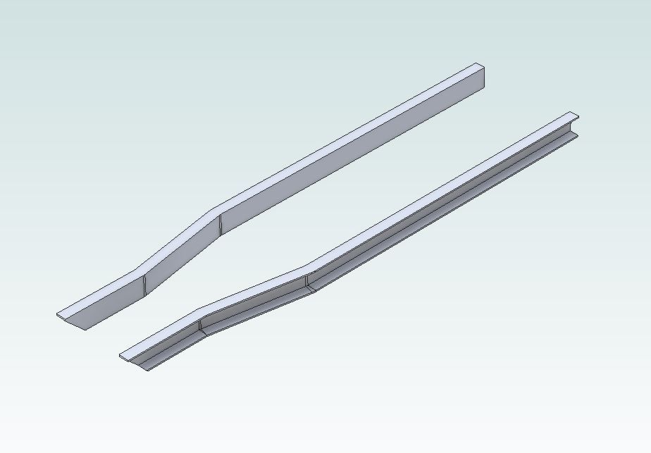
          Those chassis rails look to only be bent on plan so should not be hard to draw. Dead easy in 3D but actually produced by doing a 2D looking from above and another 2D of the end section of the "C" channel. Drew one side then mirrored to get the pair and finally chamfer cut at the front Flange taper is in there too. Just need to wipe the chalk marks off my screen nowwink 2

          chassis rail.jpg

          Edited By JasonB on 05/05/2021 10:35:09

          #543263
          DC31k
          Participant
            @dc31k

            I do not know if TC has a 'purge' or 'purge all' command similar to AutoCAD, but using that could help if it does.

            #543266
            SillyOldDuffer
            Moderator
              @sillyoldduffer
              Posted by Nigel Graham 2 on 05/05/2021 10:02:08:

              The same [Not Responding] problem arose briefly yesterday, with my large general-arrangement drawing.

              So my question…

              Is there a definite limit to the size and complexity of a drawing that TurboCAD and the computer can handle?

              Or is the problem caused by keeping all the Layers visible when working on any one part of the drawing?

              Or something else again?

              "Not Responding" isn't necessarily a fault, though it often is! Operating Systems expect any program displaying graphics to be interactive, that is 'responding' to inputs such as mouse clicks, mouse movements, and keystrokes. If none are received within a certain time and the program has consumed over a certain number system resources, the Operating System issues the 'Not Responding' warning because the symptoms often indicate a fault. But calculation heavy programs, like CAD, might legitimately exceed the warning limit.

              Is there a definite limit to the size and complexity of a drawing that TurboCAD and the computer can handle? Yes. Computers are machines and they can be overloaded. Typical limits are:

              • Number of CPUs and their processing speed. (Limits the number of operations per second.)
              • Size of Random Access Memory. (Limits the size of programs and data that can be stored in fast memory. Programs and queue if there is insufficient RAM, and when computers spend more time managing queues than doing real work the system grinds to a halt. ) Shortage of RAM is a common cause of poor performance.
              • Size of disc storage. (Limits the number of programs and the total amount of storage available. Rule of thumb, filesystems more than 80% full, or fragmented, also slow down dramatically. Although Microsoft's NTFS is much less likely to fragment than early filesystems like FAT, it's worth checking periodically)
              • Network Capacity. (Limits how quickly the computer can exchange data with other computers, again causing queues, especially when Windows is upgrading.)
              • Graphical Processing Unit. (Limits how fast graphics can be manipulated and displayed. Older computers may not have a GPU, in which case graphics are part of the CPU load.)

              Windows provides a tool for investigating these. Whilst 'Not Responding', type the CTRL-ALT-DELETE keys together, and select 'Task Manager' from the resulting Window.

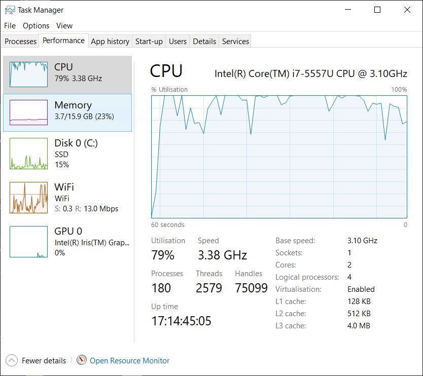
              The 'Processes' and 'Performance' tabs are interesting. Fired up my Windows laptop this morning and it was a bit sluggish; task manager revealed CPU running at 100%, shown here dropped to 79% because I was so slow getting the screenshot tool to work! Memory, Disc, Wifi, and GPU are all fine, though the SSD (15%) is a little high considering I'm not doing anything!

              processes.jpg

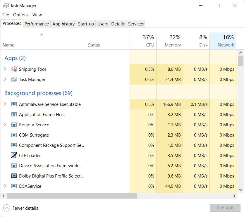
              The process screen showed the culprit, though I was too slow taking the screenshot to catch it for you!

              processes2.jpg

              The guilty program was the 'Antimalware Service Executable', turning on Windows triggered an antivirus scan which took most of the computer power for as long as it took to scan the hard disc. There are a number of resource greedy programs that can fire up in background and slow everything down. 'Not responding' might be due to one ore more of these colliding with TurboCAD. A new computer with 4 or more fast CPU cores, 32Gb RAM, a big SSD and a quick network will cope much better than a 15 year old clunker with 2 slow CPU cores, 4Gb RAM, a full slow hard drive, and dial-up networking.

              Software bugs also cause 'Not Responding', maybe TurboCAD is poorly. But check what Task Manager says first – nothing worse than spending days debugging software only to find the hardware was too small!

              Task Manager might reveal unnecessary services running, including malware. One of Windows security shortcomings is how easy it is for owners to accumulate rubbish – by making stuff easy, it opens the door to unwise operator decisions. As some malware works simply by soaking up resources, as does running a horde of unnecessary services and Start-up programs, it's a good idea to spring-clean Windows periodically.

              Dave

              #543289
              Martin Connelly
              Participant
                @martinconnelly55370

                I had issues with the antimalware running when it was not welcome. I think I changed settings to get it to run only when everything else was quiet by giving it low priority.

                Martin C

                #543305
                Nigel Graham 2
                Participant
                  @nigelgraham2

                  Thank you.

                  I spent some time this morning doing a little housekeeping on the computer, but whether it will make much difference, I don't know.

                  It hadn't occurred to me the computer had been taken over in the background by some automatic application or other.

                  I'll finish and post this then see what Task Manager says is happening. It shouldn't be much especially if I minimise this screen.

                  Jason –

                  I don't recollect previous problems as severe as they were this time. TurboCAD sometimes does need to pause and think about what I've asked it to do, but usually for only a second or two, not ten minutes just to let me re-size a selected object.

                  Looking at your drawing there, I think I can see how I can do that: draw the plan view of the vertical web with its two bends, and turn it into a "solid" wall (an Extrusion). Then do the same with the flange, extruding that but by only 5mm, copy these figures as necessary and add them together. I recall previously making "angle-iron" by joining two extrusions edge to edge then "Add" – ing them. Not sure how I would cut the front ends back to that long bevel though.

                  #543366
                  Nick Wheeler
                  Participant
                    @nickwheeler
                    Posted by Nigel Graham 2 on 05/05/2021 14:18:29:
                     
                    Looking at your drawing there, I think I can see how I can do that: draw the plan view of the vertical web with its two bends, and turn it into a "solid" wall (an Extrusion). Then do the same with the flange, extruding that but by only 5mm, copy these figures as necessary and add them together. I recall previously making "angle-iron" by joining two extrusions edge to edge then "Add" – ing them. Not sure how I would cut the front ends back to that long bevel though.

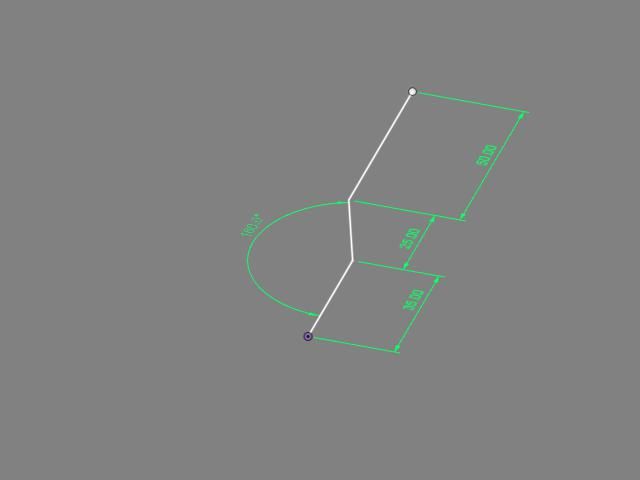
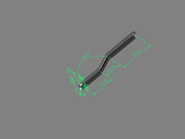
                    Why make it complicated, as it can be done with two simple, fully defined and editable sketches:

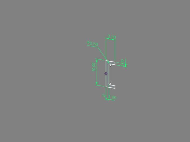
                    Sweep this profile(note the internal radii)

                    demo3.jpg


                    along this 3 line path(which could also kick up or down on another plane if needed)

                    demo2.jpg

                    to get this

                    demo1.jpg


                    The bevel would be another single line across the flat face and a 'cut' extrude. The whole thing instantly updates if you alter any of the dimensions.

                    It took longer to copy the images to my forum album than it did to create the 'model'

                    Copy, rotate and move for the other side. Draw the crossmembers directly on one of them, and extrude(they're straight) to the other one. No coordinates or working out needed

                    Edited By Nicholas Wheeler 1 on 05/05/2021 18:21:20

                    #543558
                    Nigel Graham 2
                    Participant
                      @nigelgraham2

                      Strange – Despite that "house-keeping" I mentioned above I still had what should have been a straightforward drawing freeze, my vehicle's GA, for a worrying but short time. It is very easy in TurboCAD to produce all manner of hidden, surplus fragments so there might be some in there.

                      By experiment I ran Task Manager's performance graphs while opening that GA, probably my largest drawing.

                      There were expectedly two big CPU peaks as the programme then drawing opened, but it registered very low memory use, and when I highlighted an object and moved it, the graphs barely flickered.

                      I thought the size of the drawing – 4 orthographc elevations – might be too big but it seems <400kB.

                      Jason, Nicholas –

                      Thank you for the hints, but I'm afraid I cannot produce what you say is easy, that pair of cranked chassis rails. I could draw them as Extruded sections if they were straight and parallel to an axis, but not at angles.

                      Jason

                      I think you are using Alibre and perhaps non-axial figures are easier in that. You are right – the rails are bent only in plan (I hope the real ones are, too!).

                      '

                      Nicholas –

                      What did you use there?

                      TurboCAD Deluxe 19 has no "sweep" command, according to its manual. The TC Users' Forum sometimes refers to "rail sweep", but I don't know what that does.

                      I don't think it allows dimensioning in full 3D as you have, only on elevation views. TC has associative dimensions that follow object changes, but I do not know if reciprocally.

                      The exercise proved I cannot draw in TC complicated items like those cranked channels from extrusions of the cross-section. Instead, I would have to work from the component's plan. The real metal is 50 X 25 X 5mm, but I used inches to suit the model itself, rounded to 2 X 1 X 0.2 inches. SO:

                      – 1) A thickness-extruded, 8-sided Polyline; full length, 1" wide X 0.2" deep.

                      – 2) A copy moved to one side, dropped it 1.8" (the Reference Points are in mid-metal). These are the flanges

                      – 3) A second copy, moved aside, Exploded edited and re-united as a Polyline 0.2" wide X 1.6" deep (the web).

                      – 4) Assemble the flanges to the web.

                      – 5) Copy the whole caboodle, slide the copy away, invert it, calculate from a plan-view dimension the spacing adjustment.

                      – 6) Calculate moving both rails to put the nearest corner as a datum on round-numbered co-ordinates: probably entailing some geometrical construction, because the combined Reference Point is somewhere in the middle..

                      This omits the flange tapers and roots as merely needless complexity. Even so, it proved too difficult and I realised I cannot draw the rest of the vehicle, not in 3D.

                      '

                      Forming that long bevel at the front needed:

                      – Extruding a long bar from a triangle, swinging it horizontal, Assembling it to the rails.

                      – Copying it, moving the copy aside.

                      – Subtracting the first prism from one rail – this also deletes the prism.

                      – Returning the copy for the second rail's subtraction.

                      (TurboCAD's version of "Cut" is "Object Trim", working only in 2D.)

                      Similarly I don't think it's possible to Extrude a solid to another, only extend lines to them. Normally to ensure things meet in 2D I draw them over-length and Object Trim them back. In 3D I need calculate their right lengths.

                      I calculate co-ordinates and relative moves from points on the drawings because I cannot understand the extraordinarily complicated Work-plane and Co-ordinate systems. I don't know if this complexity is just in TurboCAD or 3D CAD generally.

                      '

                      Sorry, but the concepts and methods you show are new to me, don't apply to the CAD version I have, and are more advanced than my level. I used to think I could learn 3D CAD!

                      #543577
                      Nick Wheeler
                      Participant
                        @nickwheeler

                        That's Fusion360, but Alibre that Jason used and any other 3D program is very similar.

                        You're trying to force the complex restrictions, that fudge a 3D object onto a flat piece of paper, onto a system that simply doesn't need them. Look at how complicated your description of how to do that is compared to mine.

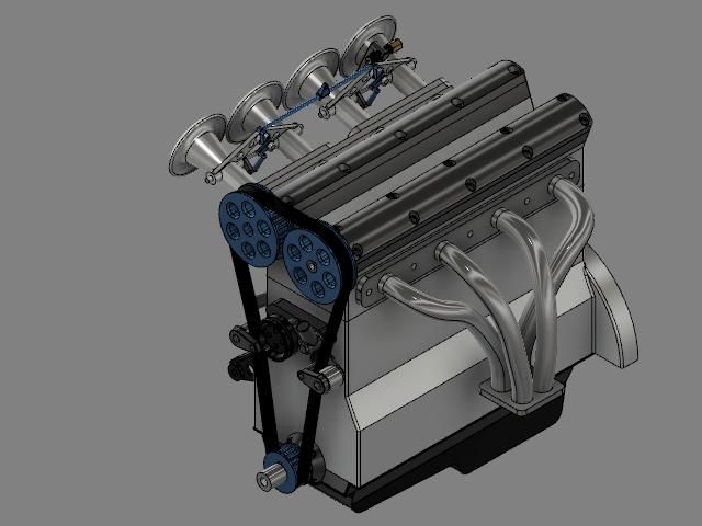
                        Turbocad's workplanes, scales and viewports confused the hell out of me so I didn't get very far with it. I've never used coordinates for anything I've done in Fusion. This

                        whole engine.jpg

                        is based entirely around this simple crank web and a known spacing of the bores:

                        crank web.jpg

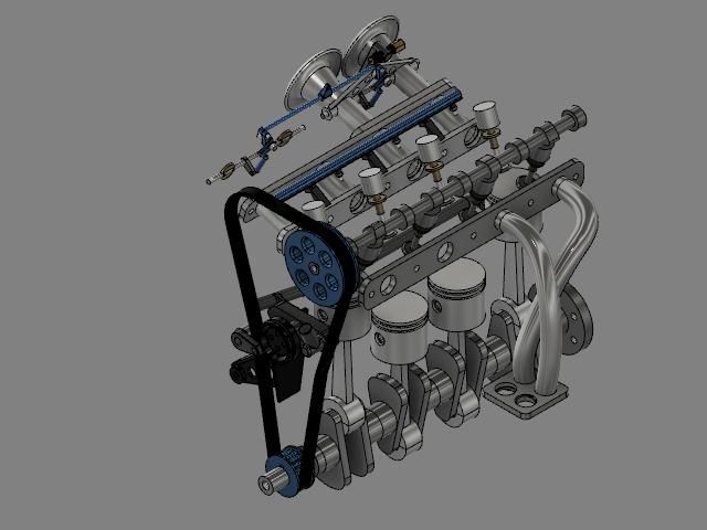
                        with all the components designed in place and can be switched on and off, or animated as needed

                        cutaway.jpg

                        I wish Fusion had a follower joint so the entire valvetrain could be animated properly. It took about a week of evenings in front of the telly, and there is no way I could do it as 2D. It does need a couple of modifications to actually produce it. Nor do I see much need for traditional flat drawings to make most of it when the models are available in any orientation or dimensions you need.

                        #543673
                        Nigel Graham 2
                        Participant
                          @nigelgraham2

                          I am impressed, Nicholas – and envy your skill! – but I do know TurboCAD lets you create similar models if you know how. I don't know though if my edition at least, gives 3D dimensioning.

                          I would not care trying to machine those parts from those model drawings, though, even with each part on a separate sheet – as industrial practice. They would be are far harder to read with the certainty of identifying the dimensions correctly. You know where they are only because you drew it as well. The isometric image is useful in the corner of the sheet, but the orthogonal elevation is far easier for making the thing.

                          The adjective "traditional" is meaningless, especially if you mean it derisively as appears. There is little in mechanical-engineering tools and methods that is not "traditional" in some form or other, because notwithstanding technical developments and innovations, the basics work! The principle of the lathe appears as old as Ancient Egypt, so is the lathe "traditional" therefore unworthy?

                          '

                          I may be wrong but I am sure I have seen references to animation in the Fusion users' forum.

                          '

                          I did not say my methods are as IMSI intends – I know they are not the proper, efficient TurboCAD way!

                          TurboCAD does not expect you to have calculate anything, but I don't know how to use it to avoid the sums.

                          TurboCAD is perfectly capable of drawings like your engine, and just as efficiently; but I don't know it well enough to let it do that for me.

                          I briefly tried Fusion, alone, and Alibre via the first couple of instalments in the MEW series. I bought a subscription to MEW, already subscribing to ME, but missed two editions so that stopped progress; then I realised changing from one CAD package to another even though comparable, would be a mistake.

                          '

                          Those other makes must have equivalents to TurboCAD's 'Work-planes', under a different name and perhaps more direct. Your crankshaft drawing bears that out. I think early in that MEW Alibre series, it highlighted a surface to develop a shape on it – that is one among several types of what TC calls a 'work-plane'.

                          'Viewport' is only TurboCAD's method of transferring the raw drawing to the printer page-size, but all CAD systems must have similar, under different names, perhaps simpler. They need to, for setting images onto any of a huge variety of both American and international-standard sizes. (I think there must be two dozen in the printer-setting menus.)

                          '

                          There is though a fundamental point beyond how well I can learn such systems.

                          TurboCAD lets you choose between orthographic elevations or isometric art-work. The former matter in the workshop, and I expect TC can develop them from 3D models but that to me is the very long way round. Isometric drawings have always had a place in engineering-drawing though, if not in the machine-shop then for, e.g., illustrating instruction-manuals. To me, draughting either manual or CAD is an engineering tool, but 3D CAD seems presented as more of an academic art-exercise. Fusion and Alibre appear not to give that choice so drawing a simple object to be made physically, is subsumed into a long and hard exercise that prioritises the drawing over the object.

                          It's like my lathe. I don't own it to admire it and swarf. I have it for making objects that can really only be made properly by turning. Hence, I bought a CAD package to help me towards making physical objects, not beautiful 3D pictures of them; but I did want the isometric function as well, as potentially useful occasionally. I was simply not prepared for just how difficult it is to make 3D CAD pictures.

                          '

                          I looked again last night at that 3D outline of my wagon; but by the only methods I know, knowing them not as TurboCAD is best used..

                          I managed the chassis frame, spaced other parts along it from a dummy cross-bar on the front, gave it rather Flintstone-esque wheels. I progressed to the bunkers but a mistake in hollowing them from their generating solids, removed their floors. The floor is a long plate extending back as the footplate and seat mounting; but I was totally unable to return to the method that worked for the bunker walls, to generate it. (It is a difficult shape, narrowing forwards to a corner with a large radius – but a possible solution has just occurred to me.)

                          At least I don't have a telly to distract me!

                        Viewing 11 posts - 1 through 11 (of 11 total)
                        • Please log in to reply to this topic. Registering is free and easy using the links on the menu at the top of this page.

                        Advert

                        Latest Replies

                        Viewing 25 topics - 1 through 25 (of 25 total)
                        Viewing 25 topics - 1 through 25 (of 25 total)

                        View full reply list.

                        Advert

                        Newsletter Sign-up