The Post Man Cometh.

Advert

The Post Man Cometh.

Home Forums Work In Progress and completed items The Post Man Cometh.

Viewing 25 posts - 26 through 50 (of 124 total)
  • Author
    Posts
  • #169622
    Nick_G
    Participant
      @nick_g
      Posted by Paul Lousick on 14/11/2014 22:42:17:

      The drawing does not show any surface finish or tolerance for dimensions. Check it they are required before you start machining.

      Paul.

      My understanding (possibly wrong) is that the drawings for Stuart engines are a 'guide' and parts should be made for 'fit'.

      Thanks for the info on the sequence. It seems logical now.

      Nick

      Advert
      #169633
      JasonB
      Moderator
        @jasonb

        Hold in 4-jaw , with spigot facing outwards and get it running as true as possible, use packing behind the flange to keep it at right angles to lathe axis. Remove packing and true up & face the spigot, you really only need the larger spigot dia so the small bit could be sawn off.

        While still in the 4-jaw face the flange to leave the boss that goes into the cylinder, use the cylinder to gauge the size as you get close . Also drill and ream right through 3/16". This will keep the 1" dia and 3/16" hole concentric and at right angles to the top face of the cylinder.

        Now hold the part by the spigot your Bison 3-jaw should be good enoght for this and face the gland boss so it is 7/16" from the machined flange face, counterbore 5/16" a drill will do for this. While held this way turn the top of the flange until it is cleaned up, leave the raised area around the gland boss as cast.

        Finally hold it the other way around and turn off the chuck spigot and face the 1" dia, not critical if its a bit less than the 1/16" long

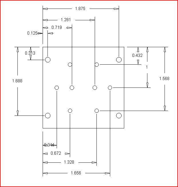
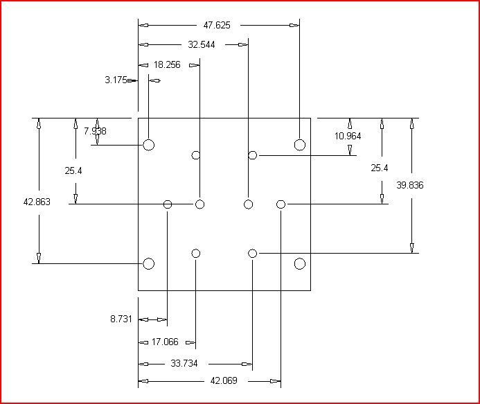
        Finally mill the 4 edges square measuring off the 1" dia, then set the part true under the mill spindle and use co-ordinates to drill the 10 holes (zeuz tables will give you the calculation for the 6 holes)

        #169659
        lancelot
        Participant
          @lancelot

          Hi follks, Jason gave a very good run down on the machining sequence…I had to do the same only ''Different'' yesterday

          reason being .when I started th build I worked to the first set of drawings…I found a problem 2 of them…the gland position was out of line with the cent of the 1'' spigit locator and the piston shaft a fair piece most of 2 mill….figured out how much to move spigot off centre and still retain working dimensions …bored for shaft and found gland appr..40 thou. off …stud positions …nottoo happy …a little off………Three years later ''Parky''' I picked up on my build again…contacted Stuarts about the cover problem …asked them if I should follow the first set of drawings ,as the latest showed 6 holes spaced against the first drg,,showed 4 spaced plus I had already fitted it to the cylinder It was agreed I should go with the original drg…….so that is exactly what I wasup to yesterday…following Jasons plan of attack 'less 2 holes'' one more thing ,,,height guage the centres of the gland stud positions and piston shaft centres front and bach of cover ….Good building.

          Edited By lancelot on 15/11/2014 11:59:51

          #169675
          Nick_G
          Participant
            @nick_g

            .

            Cheers guy's

            I shall attack this section at some point over the course of the weekend.

            I may even use my newly delivered tools from Eccentric engineering. surprise

            Nick

            #169679
            mechman48
            Participant
              @mechman48

              The coloured packing's look like the backs of diamond hones, course, medium, fine, that I have, I don't see any wedge shapes, not that wedges would be very effective anyway.

              George

              #169785
              Nick_G
              Participant
                @nick_g
                Posted by mechman48 on 15/11/2014 16:49:46:

                The coloured packing's look like the backs of diamond hones

                George

                Yup. That's what they are. yes

                Nick

                #169789
                Nick_G
                Participant
                  @nick_g

                  .

                  Some more progress made today. Although I did forget to photograph the cylinder end machining as described by Jason.


                  The piston was made.


                  And I could not resist stacking bits together to see how she was starting to look. (think I may need to 'fettle' the ports on the cylinder)


                  Nick smileywink

                  Edited By Nick_G on 16/11/2014 17:33:38

                  #169859
                  Nick_G
                  Participant
                    @nick_g

                    .

                    Are there any 'tricks', tips and general advice for drilling the PCD of holes.?

                    I know it's simple with a DRO fitted. But I have not.! sad

                    Cheers, Nick

                    #169861
                    JasonB
                    Moderator
                      @jasonb

                      As I said in my instructions the formulas for various PCD numbers are in the Zeuz book so you just multiply your 1 5/16" by these to get the x & y co-ordinates. Or is you have a CAD package that will do it for you.

                      james coombes.jpg

                      To eliminate any backlash you may have it is worth then calculating these from one corner of the part rather than the centre point of the pcd, that way your handwheels will only be turning in one direction so you don't have to worry so much about backlash.

                      If you are going to spot through the covers to get the hole locations in the cylinder then a few thou error due to backlash is nor an issue


                      J

                      Edited By JasonB on 17/11/2014 20:49:33

                      #170394
                      Nick_G
                      Participant
                        @nick_g

                        .

                        Thanks once again Jason.

                        Today I made the crankshaft and it's associated casting. Fixing them together with locktight and a 3/32 silver steel pin pressed in through the side.

                        Then it seemed a good time to machine the bearings.

                        Have a good weekend everyone, Nick

                        #170437
                        Nick_G
                        Participant
                          @nick_g
                          Posted by JasonB on 17/11/2014 16:43:39:

                          To eliminate any backlash you may have it is worth then calculating these from one corner of the part rather than the centre point of the pcd, that way your handwheels will only be turning in one direction so you don't have to worry so much about backlash.

                          I have been thinking about the backlash and the fact that my machines are graduated in metric. To someone of my limited experience it's a recipe for disaster.! blush

                          The options I have are thus. (without taking the parts to my pro engineer friends workshop and using his DRO machines.)

                          1) Buy a DRO setup myself. – Nice, but I really have other calls on my money ATM so that is probably for the future.

                          2) I have a 2" travel dial guage. – Buy a second one (20 odd quidish) and configure them to record the X & Y thus eliminating any backlash and my feeble brain issues.

                          Nick

                          #170441
                          JasonB
                          Moderator
                            @jasonb

                            3. use a claculator to convert to metric

                            4. Use your height guage to mark it out carefully, punch and drill. Use that part to spot positions onto teh second.

                            5. click a tab on the CAD to change dimensions to metricsmile p

                            jamescombesmetric.jpg

                            Edited By JasonB on 23/11/2014 12:54:39

                            #170458
                            Michael Gilligan
                            Participant
                              @michaelgilligan61133

                              Of course, Nick … Whilst you were machining the casting in the lathe, you could have just drilled the holes on a P.C.D. devil

                              MichaelG.

                              #170459
                              JasonB
                              Moderator
                                @jasonb

                                Is that before or after Nick made some means to index the lathe spindle and a toolpost powered spindle to drill the holessmile p

                                #170467
                                Michael Gilligan
                                Participant
                                  @michaelgilligan61133
                                  Posted by JasonB on 23/11/2014 16:57:59:

                                  Is that before or after Nick made some means to index the lathe spindle and a toolpost powered spindle to drill the holessmile p

                                  .

                                  … or spent an hour knocking-up a bracket for his electric drill.

                                  … and six is a pretty easy number to index.

                                  MichaelG.

                                  #170468
                                  Nick_G
                                  Participant
                                    @nick_g

                                    .

                                    Don't make the sawdust in my bonce hurt any more than it does already guy's. – At this rate I will be fixing the cylinder ends together with wallpaper paste. wink

                                    This evening I decided to machine the pedistal that supports the outer bearing.

                                    Not the strongest of set ups so I took slow and light cuts.

                                    It seemed to work out OK (except for the auto focus from the iphone wink)

                                    Over to the mill to do the base side. Again not a major sturdy set up so I again went slow and light.

                                    I gave quite a but of consideration to the mounting as I did not want to introduce even a small twist in the casting that would spring back once I took it out of the vice and leave me saying very rude words.! angry

                                    It went thankfully OK – I deviated from the plan slightly by putting a recess into the center section of the casting.

                                    Nick

                                    #170483
                                    Nigel McBurney 1
                                    Participant
                                      @nigelmcburney1

                                      To drill holes on a pcd, for example 6 or 8 holes in a cylinder cover,aquire a vertical indexing chuck with 24 positions, which provides most of the useful pitches ,and use it mounted on the vertical mill table.Its accurate and there is no backlash error or indexing of the mill table.

                                      #170485
                                      Nick_G
                                      Participant
                                        @nick_g
                                        Posted by Nigel McBurney 1 on 23/11/2014 22:44:47:

                                        To drill holes on a pcd, for example 6 or 8 holes in a cylinder cover,aquire a vertical indexing chuck with 24 positions, which provides most of the useful pitches ,and use it mounted on the vertical mill table.Its accurate and there is no backlash error or indexing of the mill table.

                                        Thanks for that. smiley

                                        I did consider this option. But a 1/2 decent one would cost as much as a DRO setup. And a 'decent' one many times more.!

                                        Cheers, Nick

                                        #170766
                                        Nick_G
                                        Participant
                                          @nick_g

                                          .

                                          I am now 4 weeks into this my first build. – But sorry Jason still no PCD holes yet.! wink

                                          Carved out the holes in the plates. Diverted from the drawing slightly as I want to give the engine a 'personal touch' with more rounded corners. (I will use that excuse later when I make a cock-up cheeky)

                                          The hole is larger on the bottom plate than the drawing says due to me having an a-la Baldrick " cunning plan"

                                          The bearings are drilled, tapped and fitted. Although they do need dressing. Nice snug fit but rotate nice and free with a dab of lubrication on the crankshaft.

                                          While on that subject what is a good oil for running in.? (when the time comes)

                                          .

                                          I wonder the stage I will be at in another 4 weeks.? – Maybe even some PCD holes eh Jason.! laughsurprisecheeky

                                          Nick

                                          #170769
                                          Martin Cottrell
                                          Participant
                                            @martincottrell21329

                                            Nick,

                                            It looks to be coming along very nicely, a fine job by any standard let alone a first attempt! It looks like quite a big engine or is that just the perspective of your photo with the engine in the foreground, what diameter is the flywheel?

                                            Regards Martin.

                                            #170771
                                            Nick_G
                                            Participant
                                              @nick_g
                                              Posted by Martin Cottrell on 26/11/2014 22:06:51:

                                              what diameter is the flywheel?

                                              Regards Martin.


                                              Thanks for the nice remark Martin. Much external advice though. – It's a 7" dia flywheel.

                                              Here is the spec on the Stuart site. :- **LINK**


                                              Regards, Nick


                                              Edited By Nick_G on 26/11/2014 22:16:33

                                              #170778
                                              JasonB
                                              Moderator
                                                @jasonb

                                                Nick looking at your marking out you could just mark, punch and drill the holes as you seem quite capable of accurate marking out. Any light oil will do but not steam oil.

                                                J

                                                #171608
                                                lancelot
                                                Participant
                                                  @lancelot

                                                  Hi Nick…how are you getting on with the Coombes ? I found that there were a few mechanical fouls on my build (possibly due to working with outdated and then the latest drawing)…

                                                  Keep her cuttin Nick…

                                                  John.

                                                  #171653
                                                  Nick_G
                                                  Participant
                                                    @nick_g

                                                    .

                                                    Hi John,

                                                    OK-ish I think. Not done so much this week but I have made the eccentric strap.

                                                    I first sliced the casting and soldered it back together before placing it in the 4 jaw. I 'tinned' the 2 halves and used spring bulldog clips to hold it together in alignment. This snapped the parts together nicely when the solder remelted.

                                                    They came apart easily after the machining was done with little heat.

                                                    The remaining solder cleaned off.

                                                    .

                                                    The next thing I intend to make is the crankshaft eccentric and would like a little bit of advice please on the best way to go about it. The supplied stock is quite short in length but I do have a longer length already if it would make things simpler.

                                                    So guy's what is the best machining order to produce the eccentric part below :-

                                                    Many thanks, Nick

                                                    #171658
                                                    Mike Poole
                                                    Participant
                                                      @mikepoole82104
                                                      Posted by Nick_G on 26/11/2014 21:57:14:

                                                      While on that subject what is a good oil for running in.? (when the time comes)

                                                      Graphogen is good for motorcycle engine rebuilds, applied as an assembly compound. Their website recommends its use for all fine machinery.

                                                      Mike

                                                    Viewing 25 posts - 26 through 50 (of 124 total)
                                                    • Please log in to reply to this topic. Registering is free and easy using the links on the menu at the top of this page.

                                                    Advert

                                                    Latest Replies

                                                    Viewing 25 topics - 1 through 25 (of 25 total)
                                                    Viewing 25 topics - 1 through 25 (of 25 total)

                                                    View full reply list.

                                                    Advert

                                                    Newsletter Sign-up