The Cambridge Turning Trials

Advert

The Cambridge Turning Trials

Home Forums Materials The Cambridge Turning Trials

Viewing 25 posts - 26 through 50 (of 71 total)
  • Author
    Posts
  • #91417
    Anonymous

      I'm puzzled by the banding. I've never seen it before over a wide range of materials and tooling, both HSS and carbide. Mind you I almost never polish after turning; may be that's why I haven't seen it before. The leadscrew pitch on my lathe is 1/4", and the banding was roughly every 40 thou, so may be not the cause? The banding was a difference in colour, metallic and dark, rather than a mechanical feature, almost like staining. I can't see what is special about silver steel that should cause it to stain. Could be a heating/cooling effect I suppose, but coolant means flood coolant, not a dribble, so why does it appear at this particular repetition rate? Anybody got any other ideas?

      If I get time this week I'll have another go and see if I can reproduce it. If so, I'll try and examine it in more detail.

      Regards,

      Andrew

      Advert
      #91418
      Nicholas Farr
      Participant
        @nicholasfarr14254

        Hi Andrew, like Russell suggests, maybe it is there all time. Could it be a metallurgical phenomenon that is caused during manufacture? If you were to normalise a piece and do the same trial, would you get the same banding effect?

        Just a thought.

        Regards Nick.

        #91591
        Anonymous

          Here is a picture of the results of another quick trial. The first 1/2", from the right, was run at 40 thou doc, 2 thou/rev, 1200rpm and no coolant. The remainder up to the first step is identical, except for coolant. The last step, on the left, was 20 thou doc, with coolant, the other parameters the same.

          Silver Steel Banding

          The finish with no coolant is torn under the magnifying glass, the other finishes are not torn, but there is a definite and regular difference in the finish, which shows up as the banding. Surface roughness measurements, from the right, are 3.15µm, 1.80µm and 2.16µm respectively. Certainly on the results from this quick test I'd use coolant on silver steel. All very confusing.

          I guess the next thing to try is a different bar, from a different supplier.

          Regards,

          Andrew

          #91594
          MICHAEL WILLIAMS
          Participant
            @michaelwilliams41215

            Hi ,

            Are ridges separate circular hoops or one multi turn screw thread ???

            #91625
            Anonymous

              Posted by MICHAEL WILLIAMS on 26/05/2012 14:24:53:

              Are ridges separate circular hoops or one multi turn screw thread ???

              Good question; and the answer is……neither. Close examination with a magnifying glass shows that the banding is in fact a multi-start thread. I counted eight starts. That implies that the phenomenon that is causing the banding is to some extent regular in time, and at a rate about eight times the spindle speed. Whether it is actually locked to the spindle speed is another matter.

              I did another couple of tests. One at 1700rpm with coolant; the banding is still there. It's difficult to tell if it is at a different spacing. I also tried a test at 1200rpm, with coolant, on a different bar, albeit from the same source. This also exhibited some banding, but much less obvious. You have to get the light on it at the correct angle to see the banding.

              On the next test I'll dig out a piece of genuine Peter Stubs silver steel and try that.

              Regards,

              Andrew

              #91991
              Sub Mandrel
              Participant
                @submandrel

                Eight starts? Probably a resonance or slight misalignment in the auto-feed setup.

                Neil

                #91997
                Martin W
                Participant
                  @martinw

                  Andrew

                  I have noticed a similar effect on some of the pieces I have turned. I have always put it down to the fact that as I cut using the manual feed on the top slide then it is caused by my turning of the handle which causes slight variations of pressure applied by the cutting tool, even when trying to be ultra careful. Again on rough cuts it doesn't seem to be apparent but on some fine/finishing cuts it can appear.

                  I wonder if in fact it is there all the time but only becomes really visible when the surface finish is smooth enough, finger marks on glass syndrome. I have seen similar when milling, both end mill and fly cutting, as any slight imperfections appear as the finish gets more mirror like.

                  Just a thought

                  Martin

                  Edited By Martin W on 02/06/2012 23:44:21

                  #91999
                  GoCreate
                  Participant
                    @gocreate

                    Hi

                    I have suffered from this banding phenomenon for as long as I have used my lathe and it can be frustrating when trying to get a really good finish. I have noticed it on most materials.

                    I have not investigated it in any depth, I assume the following may be contributing to the problem.

                    1. I am using a cheap Chinese lathe, so nothing is going to be perfect, poorly fitting surfaces/slides will be more effected by vibration than on a good quality machine.

                    2. The lathe is of light construction so has less vibration dampening effect.

                    3. There are various sinusoidal frequencies taking place from the motor, pulleys, gears in the feed train etc. each with there own frequency, these vibration frequencies periodically coincide and then separate.

                    4. Acting as such these frequencies create a pattern of vibration, the light construction and low quality slides/bearings makes the machine more susceptible to being effected which shows up in the work piece.

                    I have thought about re-mounting the motor separate from the lathe to reduce one source of vibration. Slightly eccentric pulleys, out of balance rotating parts, poor quality drive belts could all be contributing to sinusoidal frequencies in the machine.

                    So good quality comes down to hand finishing skills more than then machining quality, not a bad thing.

                    Nigel

                    PS. This spell checker is a great improvement.

                    #92001
                    Sam Stones
                    Participant
                      @samstones42903

                      Andrew,

                      You have mentioned how (under certain conditions), the swarf leaves the workpiece in short pieces. Along with Nigel’s (tractionengine42) thoughts, could the swarf be curling back on itself in some sort of regular pattern, and in doing so, rubbing against the workpiece?

                      Just a thought.

                      Sam

                      #92006
                      Clive Hartland
                      Participant
                        @clivehartland94829

                        Stubs steel is very tough and I have always had trouble getting a good finish on it, I end up using a buff stick to polish down to size.Turning is always ragged and I have at times resorted to tool post grinding on the lathe for good bearing fits.It does not seem to matter what angles you grind the tool or what materiel the tool is , it still rags up.It will be interesting to see an answer to the problem.Regarding the finish I think that it is so tough that the tool has to shear its way through the metal. This raises the bad surface finish.

                        Clive

                        #92007
                        KWIL
                        Participant
                          @kwil

                          If you use an insert tip intended for stainless steel, the swarf curls away nicely and leaves a smooth finish, cutting speed is critical. Just finished threading 16 x 1 mm thread on silver steel, with neat oil as coolant. Good smooth thread.

                          #92100
                          Russell Eberhardt
                          Participant
                            @russelleberhardt48058

                            Posted by tractionengine42 on 03/06/2012 01:09:56:

                            I have thought about re-mounting the motor separate from the lathe to reduce one source of vibration. Slightly eccentric pulleys, out of balance rotating parts, poor quality drive belts could all be contributing to sinusoidal frequencies in the machine.

                            I don't know what sort of motor you use but the biggest improvement I have made in surface finish from both my lathe and mill has been to replace the single phase moters with three phase and inverters. The torque of q three phase motor is (virtually) independent of the shaft angle.

                            Russell.

                            #92103
                            Anonymous

                              Sorted! Thanks one and all for the suggestions; they helped me clarify my thoughts and identify the problem. A special mention for Nigel, who, in essence, identified the actual issue.

                              A quick look at a number of previous turning exercises showed a very slight banding on stainless steel, but on nothing else as far as I could see. This tells us the problem is not specifically related to silver steel, but may be related to tougher materials, and hence higher cutting forces. My lathe is a Harrison M300, on the makers stand, and solidly bolted to a concrete floor. It is three phase and runs from a true three phase supply. The chuck is a Burnerd high speed collet chuck. Thus I discounted vibration from the machine itself, or the main motor. I calculated a few frequencies for spindle speed and the rough frequency of the banding, but no obvious resonances sprang to mind. I didn't do the calculations for the drive train, as the fine feeds are driven by a separate drive shaft rather than the leadscrew.

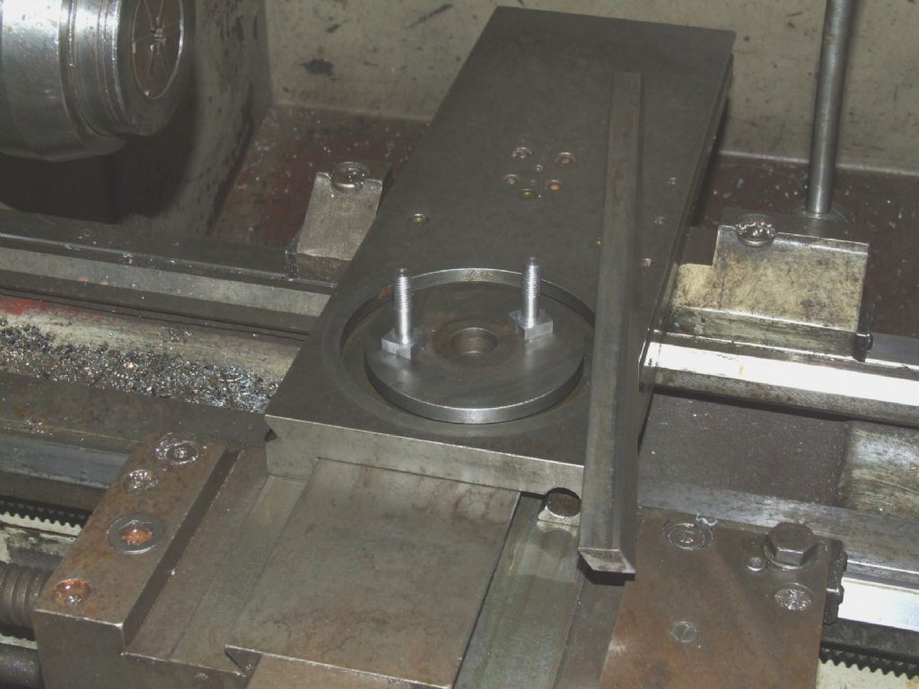
                              Now what I didn't tell you is that the cross slide is a fairly easy fit, and one of the bolts that holds the top slide down is a bit iffy. enlightened Yes, I know it's obvious in retrospect but us country boys are a bit slow on t'uptake.

                              The task this morning was to make and fit two new T-bolts for the top slide, like this:

                              T_Nuts

                              As an aside I discovered that the cross slide tapered gib has a special brass insert and grub screw pressing on it from the side of the cross slide, as well as the normal adjustment screws each end. I never knew that! It's not mentiond in the manual either, although it is shown in the exploded parts drawing.

                              With everything cleaned, adjusted and re-assembled I tried another couple of tests on the original silver steel bar. Both tests were done at 1200rpm, 0.2mm radius insert, depth of cut 20 thou, and feedrate 2 thou/rev, one test with coolant, one without. In both cases the swarf came off as a long open spiral. Both surfaces look pretty uniform under the magnifying glass, with just a hint of tearing in places, although the finish doesn't feel rough. Surface roughness measurements (Ra, µm) are:

                              With coolant: 2.15 1.72 2.10 Average=1.99

                              Without coolant: 1.40 1.55 1.40 Average=1.45

                              So in this case without coolant seems better, which is what I would have originally expected.

                              As is so often the case the solution to what seems to be a mysterious effect is actually very simple, in this case operator stupidity. sad I should have fixed the iffy bolt issue long ago.

                              Regards,

                              Andrew

                              #92120
                              Ian S C
                              Participant
                                @iansc

                                I think it was in the early 1990s, an artical in MEabout a similar problem, It was reduced, first bu mounting the motor on a rubber pad, with rubber bushes for the mounting bolts, isolating the motor from the lathe metalicly, then from what I remember the belts were changed for link belts. The motor was single phase, and three phase was concidered to be the best way to overcome vibration, but the isolation system was the cheapest. Ian S C

                                #93558
                                HasBean
                                Participant
                                  @hasbean

                                  Firsly, apologies to Andrew for hijacking this thread but I thought this was the best place for this rather than start another!

                                  Pictures below are on a piece of unknown BMS (originally 35mm embarrassed&nbsp

                                  Only 2 feeds used, 2 thou and 10 thou, depths 1/2 thou and 5 thou, speeds 600rpm and 1800 rpm, all mixed and matched but with a smear of neat cutting fluid applied first..

                                  My deductions are that I'm more confused now than before!

                                  Undoubtably rigidity has a lot to do with it as the inserts just scraped on the surface making a right mess, speed, depth, feed, nothing made any difference.

                                  But chipbreaker form did!

                                  The middle section was using a high positive rake insert, 1/2 thou depth at 600 rpm. My diamond toolholder turned the 'ring' at the righthand side end (finish is better than it looks in the picture) but high rake on a less rigid machine seems to be the answer for me at least as far as surface finish is concerned.

                                  (I also now have a decent collection of about 15 different types of 0.4mm CCMT inserts)

                                  Paul

                                  p1010366.jpg

                                  p1010368.jpg

                                  p1010370.jpg

                                  p1010369.jpg

                                  p1010367.jpg

                                  #93559
                                  KWIL
                                  Participant
                                    @kwil

                                    Andrew,

                                    You have discovered the cross slide lock (at last)! There is one on the topslide as well.

                                    Edited By KWIL on 02/07/2012 18:37:35

                                    #93578
                                    Anonymous

                                      Paul: Feel free to add to the thread at any time. The finish on the central part looks very good. Can you expand on the high positive rake insert; manufacturer, bought from where?

                                      KWIL: Well blow me down, so that's what it is for! Us country yokels might be slow, but we do get there in the end. Where's the lock on the top slide? I normally just tighten up the gib strip on the top slide so it can't be moved; unless I need to use it.

                                      Regards,

                                      Andrew

                                      #93621
                                      KWIL
                                      Participant
                                        @kwil

                                        Small socket grub screw half way along lefthand side viewed from handle

                                        #93624
                                        HasBean
                                        Participant
                                          @hasbean

                                          Andrew, The inserts that gave the best finish at low depths of cut were Korloy inserts from Cutwel. Basically I ordered one of just about all of them to try. I found that the PVD coated inserts worked much better than the CVD coated ones and the best of the lot were CCGT-AK inserts in grade PC230 (which don't seem to be listed in their new catalogue, only in DCGT style).

                                          The AK chipbreaker seems to be identical to the high rake aluminium style inserts but work better on steel.

                                          Paul

                                          #93669
                                          Anonymous

                                            KWIL: So there is, I wondered what the extra hole was for. One learns something every day!

                                            Paul: Thanks for that. A while back I did try fine cuts with a high rake insert intended for aluminium but the results were inconclusive. However it is instructive that the Cutwel catalogue states that the CCGT-AK insert is for both aluminium and for finishing on steel. I'll have to buy some and repeat the experiment. It's a shame that I had a letter from Cutwel recently offering me a 10% discount as I hadn't ordered from them for a while, but the offer ran out last week. crying

                                            Regards,

                                            Andrew

                                            #93674
                                            HasBean
                                            Participant
                                              @hasbean

                                              Hi Andrew,

                                              The CCGT-AK insert is available in two different grades, H01 for aluminium (I've tried the Greenwood version of this on steel with reasonable results), and PC9030 for stainless which I'm guessing replaces PC230 which I found the best so far on steel.

                                              Regards,

                                              Paul

                                              #93914
                                              Anonymous

                                                Paul: I've just recieved a summer special offers flyer from Cutwel that includes the CCGT-AK inserts in H01. I'll get some to see how they perform.

                                                Regards,

                                                Andrew

                                                #99425
                                                Anonymous

                                                  Not so much a turning trial as a precursor to one. Yesterday, having consulted the bank manager, I fired up the electric furnace to normalise the cold drawn blanks for my traction engine front wheel spokes. At the same time I decided to harden a couple of silver steel bushes for the traction engines and a length of 20mm silver steel ready for some turning trials on hardened steel.

                                                  I set the furnace for 780°C, and once it got there, let it soak for 45 minutes. I then threw the bushes, and plunged the bar, into a bucket of brine. The bushes came out really hard, but the the bar didn't.

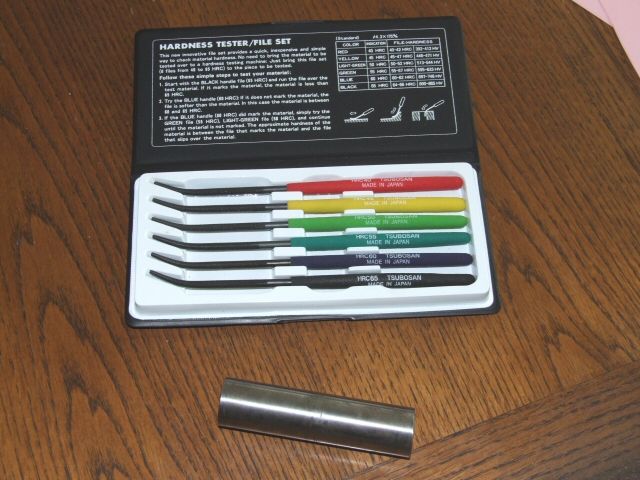
                                                  I decided that this was because I hadn't agitated the bar when it was quenching. So, having taken the furnace up to 900°C and let it soak for normalising, I had another go at hardening the bar on the way down. This time, after another 45 minute soak at 780°C, I plunged the bar into the bucket of brine and agitated it as vigourously as I could. This time the bar came out pretty hard. Here's a picture of the bar and my hardness testing files:

                                                  hardness_sized.jpg

                                                  The idea is that you start with the black file, 65Rc, and work your way down to the red file, 40Rc. The hardness of the test piece is between the file that marks and the one below that doesn't. The first time around even the red file would mark the bar. frown The second time around the black file marked the work, but the next one down, blue 60Rc, would not. So the hardness of the bar must be between 60Rc and 65Rc. smiley I think this is about as hard as is possible with silver steel.

                                                  In due course I'll have a go at turning the test bar, in it's hardened state, using a normal carbide insert and a special CBN insert for hardened steels.

                                                  Regards,

                                                  Andrew

                                                  Edited By Andrew Johnston on 26/09/2012 11:58:17

                                                  Edited By Andrew Johnston on 26/09/2012 11:59:35

                                                  #99437
                                                  Raymond Anderson
                                                  Participant
                                                    @raymondanderson34407

                                                    Andrew, I use EN16T and EN24T a lot [I get it for free] . The best inserts I have used are Walter Tiger Tec WPP05 and WPP01, excellent insert life and lovely finish. I will put a photo into my album tomorrow of a piece of Ø 60mm that was straight off the lathe.

                                                    Regards,

                                                    Raymond.

                                                    #99443
                                                    Sam Stones
                                                    Participant
                                                      @samstones42903

                                                      Hi Andrew,

                                                      Although not very scientific, but in connection with relative hardness, I’m reminded via your notes of when it became necessary to make a tiny boring `bar’.

                                                      With a Myford Super 7 running at its top speed of about 2000 rpm, the `bar-stock’ was a 1/4" diameter HSS tool bit. I needed one end to be reduced to a little less than 1/8" diameter over a length of about 1/2". A small blip left on the end became a typical boring-tool cutting edge. The cutter I used in the lathe was hand made, with a tungsten carbide tip silver soldered in place.

                                                      Under these conditions, the `fireworks' were impressive.

                                                      I suppose I could have ground the general shape by hand, but the above method was much quicker and not so hard on the fingers.

                                                      The year? c.1959

                                                      Regards,

                                                      Sam

                                                    Viewing 25 posts - 26 through 50 (of 71 total)
                                                    • Please log in to reply to this topic. Registering is free and easy using the links on the menu at the top of this page.

                                                    Advert

                                                    Latest Replies

                                                    Home Forums Materials Topics

                                                    Viewing 25 topics - 1 through 25 (of 25 total)
                                                    Viewing 25 topics - 1 through 25 (of 25 total)

                                                    View full reply list.

                                                    Advert

                                                    Newsletter Sign-up