Testing Models

Advert

Testing Models

Home Forums Stationary engines Testing Models

Viewing 25 posts - 101 through 125 (of 125 total)
  • Author
    Posts
  • #500996
    Turbine Guy
    Participant
      @turbineguy

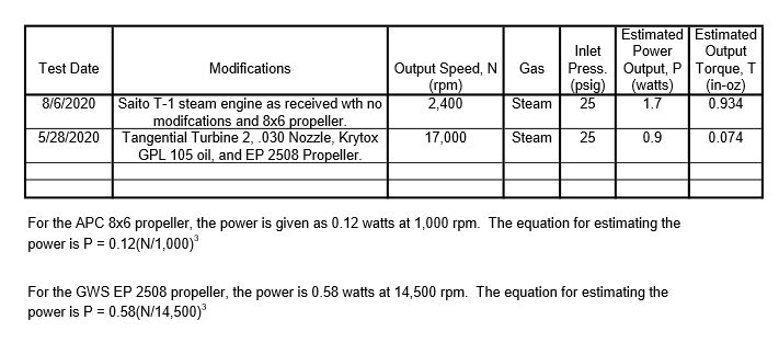
      The following chart shows the performance of the turbine, steam engine, and boiler described in the last post. Both Turbine 2 and the Saito T-1 engine are affected by the way I tested them with propellers. The propellers blew cold air over the outside of them preventing the turbine housing and steam engine cylinder from getting very hot. The large mass of the turbine housing made it even worse by taking a relatively large amount of the available energy to change it’s temperature. The steam turbines have an additional disadvantage. In addition to the energy lost by condensation of the steam, the moisture in the steam reduces the efficiency by a factor of approximately 1.3 times the percent of moisture. Turbine 2 should have the unnecessary material removed from it’s housing and be insulated. The Saito T-1 engine has a relatively small cylinder wall thickness which reduces the mass needed to be heated to a minimum. It also has a very small heat transfer area to the standard, so the heat conducted to the standard and base is minimal. Also the thin Saito T-1 cylinder reduces the heat transfer area to the air so the radiant and convective heat losses are minimized. The video showing the Saito T-1 engine propelling a boat I mentioned in the last post can be seen at this Saito T-1 Video Link.

      Steam Tests

      Advert
      #502974
      Turbine Guy
      Participant
        @turbineguy

        In a conversation with Mike Tilby, the subject came up about my first turbine project. I helped in the design of a turbine for Lear Motor Corporation. This turbine originally was intended to run on an organic fluid to keep the speed of the turbine lower. None of the efforts to keep the organic fluid from breaking down in the boiler worked, so eventually the design was changed to running on steam. Lear found people talented enough to design and make the bearings, seals, and gears operate at 60,000 rpm. I left Lear Motor Corporation before the turbine was ever tried in a vehicle. I was too young at the time to realize the importance of keeping records of my early projects so I don’t have any of the test results I was involved with in the development of the turbine. In trying to find out the actual output of the turbine, I found the articles shown in the following Lear Bus Link. The articles included in this link have enough information to evaluate the maximum performance of this turbine. I thought I would compare this turbines performance with that of one of Abner Doble’s steam engines that was probably one of the best ever put in a car. I got the test results of the Doble Model E engine from the book ‘Doble Steam Cars, Buses, Lorries, (trucks) and Railcars’ by J. N. Walton. The following table gives the results of this comparison. The Doble test was run June 16, 1928, so even though this engine was made 44 years before the Lear turbine, it had higher efficiency. Neither of my sources told what accessories were included in the tests, so the comparison might be slightly unfair. The water pump alone is a fair amount of power for these mass flows and pressures. I know this is a testing models thread, but I thought some of you might find this interesting.Lear Doble Comparison

        #504292
        Turbine Guy
        Participant
          @turbineguy

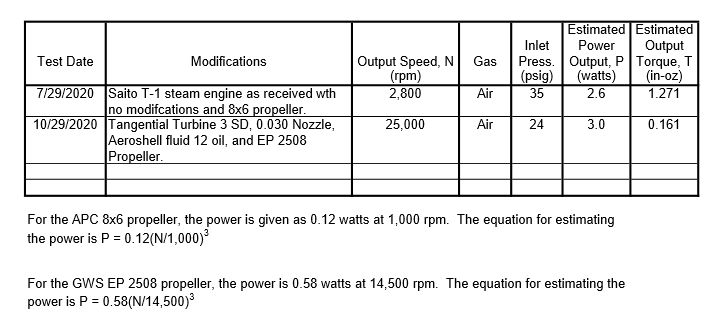
          I have been running my Turbine 3 SD on air trying different combinations of shims on the rotor and clearance between the collar and the outer ball bearing. The best combination was with 7 shims on the rotor and 0.004” spacing between the collar and outer ball bearing. With this combination, I got the highest speed running on air with my EP 2508 propeller of any of my turbines. The speed obtained was 25,000 rpm. The post of 29/07/2020 in this thread showed the results for the test of the Saito T-1 steam engine running on air. The Saito T-1 had the best performance of all my small steam engines running on air or steam. The following chart shows a comparison of Turbine 3 SD and the Saito T-1 steam engine running on my airbrush compressor. Since Turbine 3 SD has turned out to be my best performing turbine and I have only showed the modifications to make the side discharge (SD) in the Model Turbines thread, I will show these changes in the next posts. The post of 27/09/2020 in Model Turbines is the start of the discussion of the change to side discharge.

          Air Tests

          #504303
          Turbine Guy
          Participant
            @turbineguy

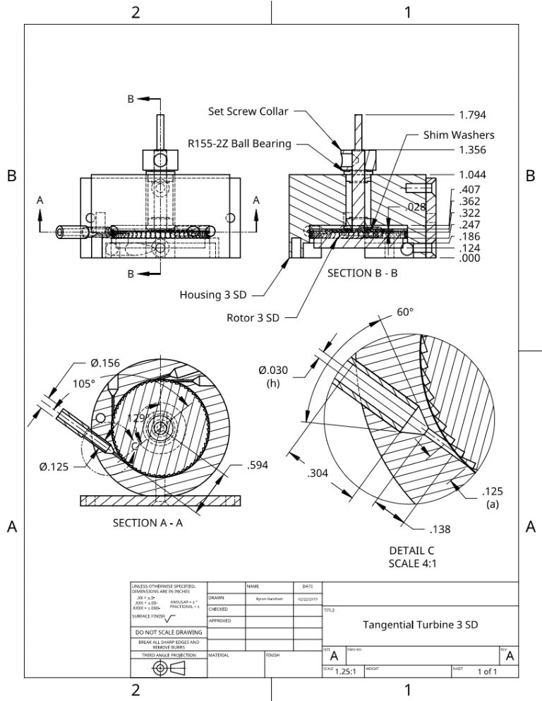
            The following drawing shows the dimensions of the nozzle and rotor in turbine 3 to change to side discharge (SD). This drawing also shows the position of the parts that gave the best performance. The position of the new nozzle was the result of trying to add other nozzles that failed by the drill drifting or breaking. This was about the only space left. Ideally the nozzle would be placed at the top of the turbine so that condensed steam would not collect around the nozzle. The next post will show the changes of the rotor to make it side discharge.

            Tangential Turbine 3 SD RA

            #504306
            Turbine Guy
            Participant
              @turbineguy

              The following drawing shows the Turbine 3 rotor modified to side discharge (SD) by removing one row of pockets.

              Tangential Rotor 3 SD

              #507910
              Evan Lewis
              Participant
                @evanlewis60038

                I found this discussion very interesting. Thank you! I have done some similar calculations for a Hero engine which I documented in a web site that you might find interesting, although I think your knowledge is much more advanced than mine. I am now building a double acting two cylinder steam engine and was interested in the results for different types of piston seals. I will post that separately.

                http://www.HeroSteamEngine.com

                #507987
                Turbine Guy
                Participant
                  @turbineguy

                  Hi Evan,

                  I’m glad you found this thread interesting. Those of us that go so deeply into the details, are a very small minority. I followed your link and found your discussion of the Hero turbine very enlightening. What you found in trying to find the best compromise between leakage and friction will be your biggest challenge with the piston seals. I have discussed in this thread tests of several small steam engines with different piston seals you might find useful. Most of these tests were with air since it was much easier to setup, eliminated the effect of moisture content, and the output of my airbrush compressor was more consistent. If you run on air and lubricate the engine by putting a few drops of oil into the inlet before starting your test, you can only run a short time before the oil escapes. Packing that absorbs the oil will extend the useable run time. My tests with steam and the displacement lubricators indicated that they work for much longer run times. I look forward to what you find in your testing of the piston seals.

                  Keep up the good work,

                  Byron

                  #508160
                  Evan Lewis
                  Participant
                    @evanlewis60038

                    Hi Byron,

                    Thanks for your reply. I was interested in a comment in the thread that the turbine jets go "sonic" at 25 psi. I suppose this is the pressure at which the fluid velocity reaches the speed of sound and cannot go any faster. Is that correct. I did similar calculations for the Hero engine and concluded that it occurred at 10-14 psi but I may not have taken into account all the factors such as the increase in density as pressure increases. I was very surprised that it occurs at such a low pressure even if is 25 psi. Because the Greeks probably could not deal with high pressures my Hero engine had a pressure relief valve set at 15 psi.

                    Are you able to explain in simple terms why the Hero reactive turbine is so much less efficient than other turbines which are so efficient that they are used in nearly all oper stations. I wrote an article on the history of a local engineering company, A&G Price and they claimed that their Pelton wheels were 90% efficient. Using the data they provided I checked their calculation and it was correct, but I don't know how reliable their data was.

                    I have started building a double acting 2 cylinder horizontal steam engine from scrap metal using only a lathe. I put a post under the heading "Stationary Steam Engines". I read the above posts about measuring the effectiveness of piston seals under pressure. For simplicity I am thinking of using O-rings for piston seals. To keep friction down I understand they would be fitted loosely. I imaging they should only just touch the cylinder walls with no perceptible compression. Is that right? The main cylinders are 22mm diameter so I would by O-rings with 22mm outside diameter but they are sold by inside diameter so 18mm rings 2mm thick would do it. Is that right? Then the grooves would be 2mm deep I think.

                    I am using pistons as valves instead of the usual flat plate so that I can do it easily on the lathe. The valve cylinder is penetrated by numerous ports: 2 steam inlets, two exhaust ports, and two ports leading to the top of the main power cylinder. They are round holes drilled rather than slots. Can I use rings on these valve pistons too or will they get torn up by the ports? Ideally the valve pistons should seal along their whole length but two O-rings or any other kind of rings would not do that.

                    Our hardware shop says they can get two kinds of O-ring: Nitrile eg N70 which are recommended for temperatures up to 90 degrees C, and red Vitron up to 200C. I assume I would need the Vitron type.

                    You may not want to read more and this is just an aside: I bought a BMW X5 second hand at 100,000km. It leaked water like crazy but passed a pressure test by three different organizations including AA. My radiator man found that it had 5 O-rings from China that had gone soft and gummy, completely flattened. Replacing them fixed the problem and he said this was very common with Chinese O-rings. But why did it pass pressure tests? They were associated with the expansion chamber which is part of the pressurized system. I think they must seal under pressure and leak when the pressure drops.

                    Thanks for your help.

                    Evan

                    #508162
                    Evan Lewis
                    Participant
                      @evanlewis60038

                      Hi Byron,

                      I was interested in your mention of Doble: "I thought I would compare this turbines performance with that of one of Abner Doble’s steam engines that was probably one of the best ever put in a car. ". The engineering Co A&G Price Foundry I was talking about had a license to male Doble steam buses for Auckland City. Would they have been turbines?

                      Evan

                      #508193
                      bernard towers
                      Participant
                        @bernardtowers37738

                        Evan , I think the o rings you are looking for are made from Viton. Just a word of warning, back in the day while still working we received a memo about not touching viton rings that had reached a high enough temp to have changed colour as they were thought to have carsonegenic properties. Not saying don’t use them just be careful.

                        #508212
                        Turbine Guy
                        Participant
                          @turbineguy

                          Hi Evan,

                          I will try to answer the questions from your last two posts partially copied below.

                          I was interested in a comment in the thread that the turbine jets go "sonic" at 25 psi. It is important to show the pressure as absolute (psia) or gage (psig) and the gas (steam, air, etc.). The critical pressure ratios are 0.528 for air, 0.547 for superheated steam, and 0.577 for saturated steam. For air with the exit pressure being atmospheric (14.7 psia), the inlet pressure would have to be 14.7/0.577= 25.5 psia = 10.8 psig to go sonic.

                          Are you able to explain in simple terms why the Hero reactive turbine is so much less efficient than other turbines which are so efficient that they are used in nearly all operating stations? The problem with the Hero turbine is the very high speed (approximately twice the speed of an impulse turbine) required to obtain reasonable efficiencies

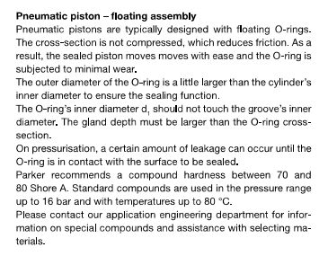
                          For simplicity I am thinking of using O-rings for piston seals. To keep friction down I understand they would be fitted loosely. I imaging they should only just touch the cylinder walls with no perceptible compression. Is that right? I tried both floating and light compression of the O-rings. The floating type as described in the follwoing link worked best. Floating O-ring

                          I am using pistons as valves instead of the usual flat plate so that I can do it easily on the lathe. Can I use rings on these valve pistons too or will they get torn up by the ports? Both of my steam engines that use piston valves rely on a close fit and have very low leakage. Whatever gain you get with seals will probably be offset by the extra friction.

                          Our hardware shop says they can get two kinds of O-ring: Nitrile eg N70 which are recommended for temperatures up to 90 degrees C, and red Vitron up to 200C. I assume I would need the Vitron type. I used the Viton.

                          My radiator man found that it had 5 O-rings from China that had gone soft and gummy, completely flattened. But why did it pass pressure tests? If the pressure is enough to move the O-ring, it will press against the sealing surfaces and stop the leakage.

                          The engineering Co A&G Price Foundry I was talking about had a license to male Doble steam buses for Auckland City. Would they have been turbines? I think the only steam buses tried in California were the Lear turbine. There were other competitors and might have been tried.

                          Edited By Turbine Guy on 18/11/2020 14:30:33

                          #508280
                          Turbine Guy
                          Participant
                            @turbineguy

                            Hi Evan,

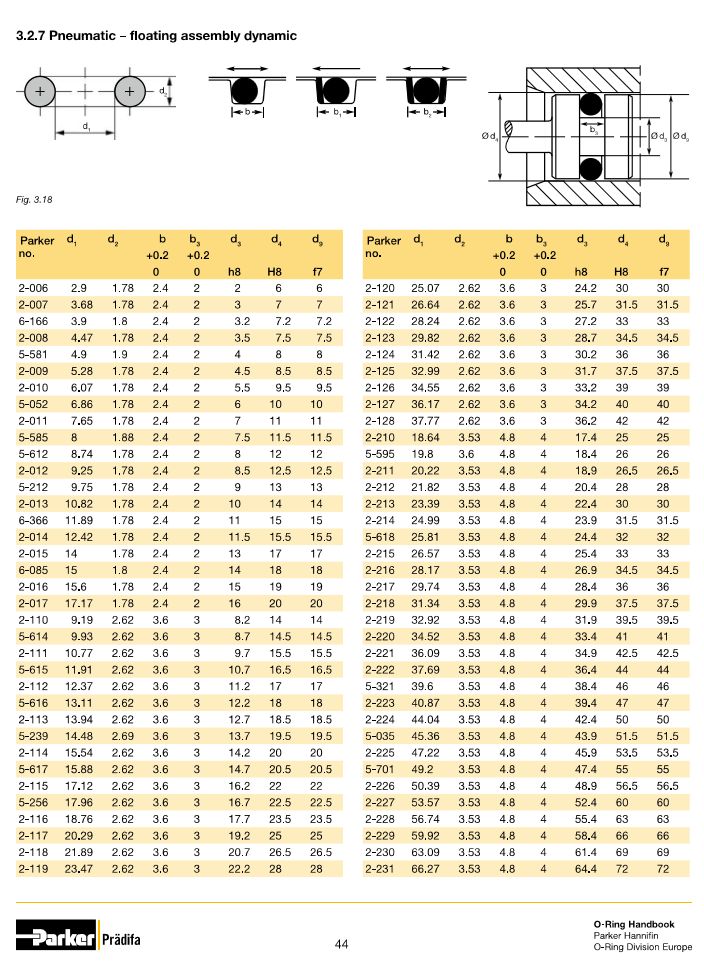
                            The following was copied from the Parker Metric O-ring catalog. It explains the concept of the floating O-ring. In the next post I will show a copy of the table that gives the groove dimensions for the metric floating O-rings.

                            Metric Floating O-ring 1

                            #508282
                            Turbine Guy
                            Participant
                              @turbineguy

                              Hi Evan,

                              The following table shows the groove dimensions for the 2-115 size O-ring you will need for your 22mm bore. The amount of leakage with the floating O-ring is more than offset with the reduction in friction. You can also use packing in the groove if you want to try that. The pest performing packing I have tried was suggested by Thor. I spun Teflon tape into a thread and wound it into the O-ring groove as tight as I could. When you add oil the small spaces in the packing absorbs some of the oil and it wicks out while running. The wicking of the oil and the lubricity of Teflon reduces the friction considerably.

                              Metric Floating O-ring 2

                              #508507
                              Turbine Guy
                              Participant
                                @turbineguy

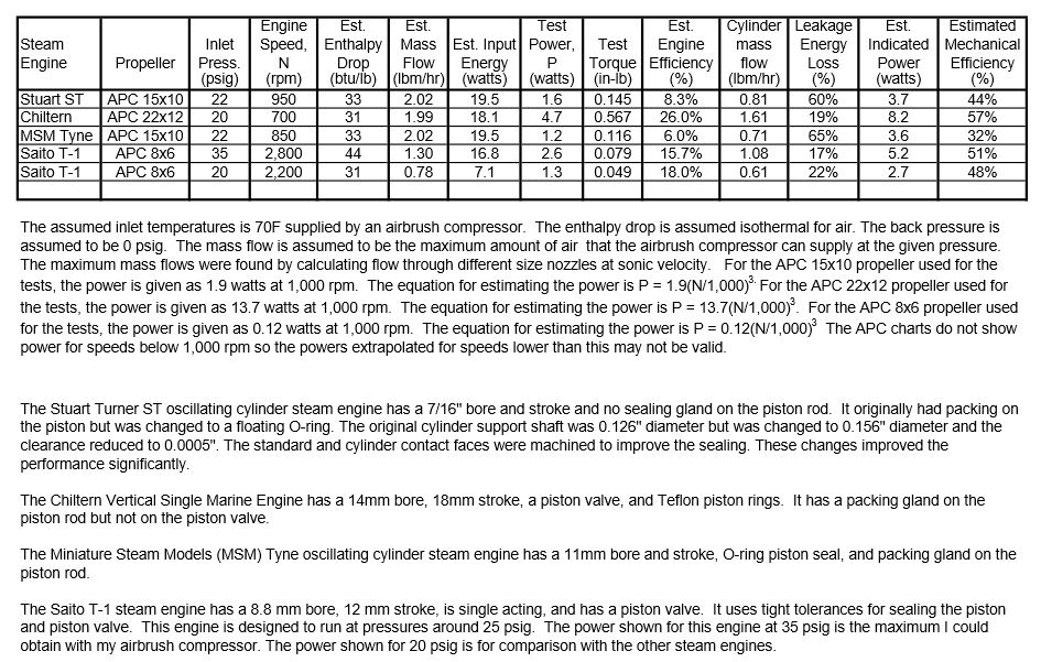
                                I updated the table shown in the post of 12/07/2020 to include the tests of the Saito T-1 steam engine. I added a disclaimer to the notes included with the chart that the test power shown for speeds below 1,000 rpm may not be valid. The performance given by APC for their propellers is not shown for speeds below 1,000 rpm but since the power coefficient increases at lower speeds due to the Reynolds number effects, the test power shown should be conservative for the lower speeds.

                                My Steam Engines 3

                                #545068
                                Turbine Guy
                                Participant
                                  @turbineguy

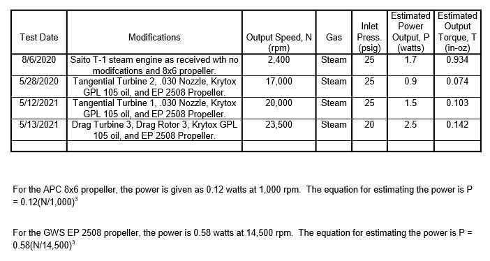
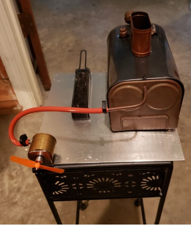
                                  It has been a while since I updated this thread. I made a new type of turbine called a Drag Turbine that is explained in the Model Turbines thread starting with the 09/12/2020 Post. If you start with this link and read the Model Turbines thread to the last post, it will bring you up to date on all the changes and testing I have done since I last updated this thread. The following is the table I showed in the last post in the Model Turbines thread that is an update to the table shown in the 12/10/2020 Post of this thread. This table summarizes what has worked best for the turbines and steam engines I have tested running on the low pressure and low energy that my small Stuart Twin Drum boiler is capable of. The photo below shows Tangential Turbine 2 connected to the Stuart Twin Drum boiler.

                                  Steam Tests 2

                                  Turbine 2 Steam

                                  #606817
                                  Turbine Guy
                                  Participant
                                    @turbineguy

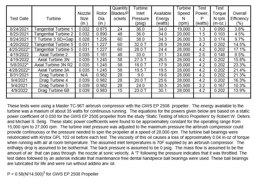
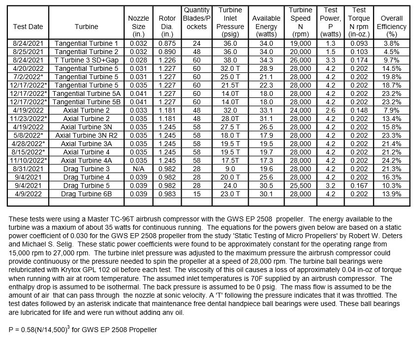
                                    It has been over a year since I added anything to this thread. All my testing since the last post has been with turbines and posted in the Model Turbines thread. If you start with the 14/05/2021 Post and read the Model Turbines thread to the last post, it will bring you up to date on all the changes and testing I have done since I last updated this thread. The following chart summarizes the results of the testing done during this time. I added folders in my photos album showing the pictures, drawings, and test results for each of these turbines.

                                    I bought a twin cylinder airbrush compressor described in the 14/08/2021 Post that is capable of spinning the propellers used on my steam engines to speeds over 1000 rpm. This airbrush compressor has approximately twice the output energy of the one I was previously using. I will update this thread in the next posts adding the test results of running my steam engines on this larger airbrush compressor and adding folders for each of my steam engines.
                                    turbine test results 37.jpg

                                    #606931
                                    Turbine Guy
                                    Participant
                                      @turbineguy

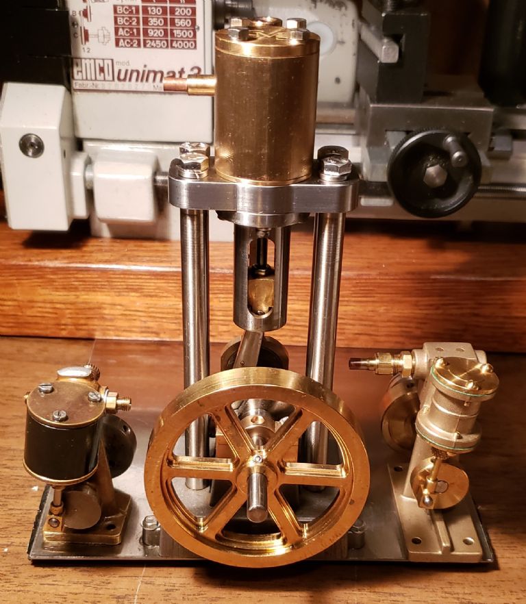
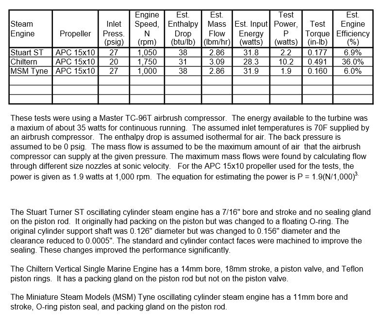
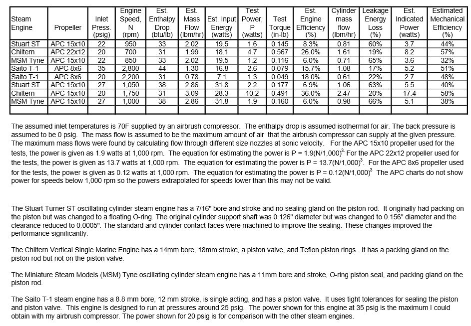
                                      I created photo albums for all my steam engines. I hope this makes it easier to see the details of an engine when it is mentioned or shown in a test report. The following photo shows the steam engines I recently ran with the twin cylinder airbrush compressor mentioned in the last post. The Stuart ST is on the left, the Chiltern is in the center, and the MSM Tyne is on the right. I left out the Saito T1 steam engine since the smaller airbrush compressor I had been using had enough energy to make the pressure higher than it was designed for. The test sheet shown below is a simpler version than shown in the 19/11/2020 post. Estimating the leakage loss and the mechanical efficiency is very time consuming. I can add this to the test sheet if this is helpful.

                                      steam engines.jpg

                                      my steam engines 4.jpg

                                      #607208
                                      Turbine Guy
                                      Participant
                                        @turbineguy

                                        I noticed that the drawings showing the piston and valve locations I had added to the Chiltern Steam Engine folder were for the modifications I thought would improve the performance. These drawings are shown in the posts starting with the 01/02/2019 post. I deleted these drawings from that folder and added similar drawings which are for the unmodified version that was tested.

                                        #607909
                                        Turbine Guy
                                        Participant
                                          @turbineguy

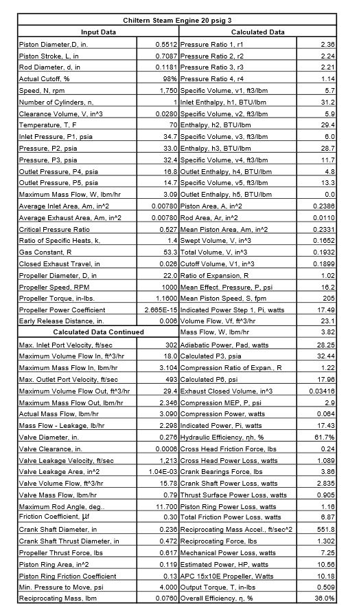
                                          As I stated in the 22/07/2022 post, estimating the leakage loss and the mechanical efficiency is very time consuming. The following spreadsheet is what I used for estimating these for the last test of the Chiltern steam engine. I estimate the pressure change required to fill the cylinder and empty the cylinder in the time available. I use these pressures to calculate the enthalpy and specific volume of the gas at each step of the cycle. For air, these are calculated based on an isothermal process. For steam, I use the steam tables and Mollier chart from Thermodynamic Properties Of Steam by Keenan and Keys, first edition. I estimate the leakage, compression, and the friction losses for these pressures. This was the way I estimated the data shown in the test sheet in the 19/11/2020 post. I think estimating the leakage and mechanical losses are important to understand the strengths and weaknesses of different types of steam engines. I decided to try a simpler method to estimate these losses which I will explain in the next post. chiltern spread sheet 3.jpg

                                          #607938
                                          Turbine Guy
                                          Participant
                                            @turbineguy

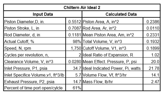
                                            I read through the section on steam engines in Mark’s Standard Handbook for Mechanical Engineers, tenth edition, by Eugene A. Avallone and Theodore Baumeister III. They stated that a diagram factor of between 0.7 and 0.95 could be used to estimate the actual indicated power from the theoretical indicated power. The theoretical indicated power can be estimated relatively easily as shown on the following spreadsheet. The mass flow into the cylinder can also be estimated with the input data shown. I updated the test sheet shown in the 19/11/2020 post to include the latest tests of my steam engines shown in the 22/07/2022 post using the data from the spreadsheets like the one shown below of each of the steam engines and using a diagram factor of 0.8. You can see that the results look very similar to those found using the methods described in the last post.

                                            chiltern air ideal 2.jpgmy steam engines 5.jpg

                                            #625662
                                            Turbine Guy
                                            Participant
                                              @turbineguy

                                              It has been a while since I added anything to this thread. All my testing since the last post has been with turbines and posted in the Model Turbines thread. If you start with the 01/08/2022 Post and read the Model Turbines thread to the last post, it will bring you up to date on all the changes and testing I have done since I last updated this thread. The following chart summarizes the results of the testing done during this time. I added folders in my photos album showing the pictures, drawings, and test results for each of these turbines.

                                              turbine test results 44.jpg

                                              #625690
                                              Turbine Guy
                                              Participant
                                                @turbineguy

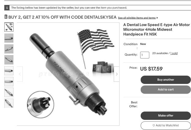
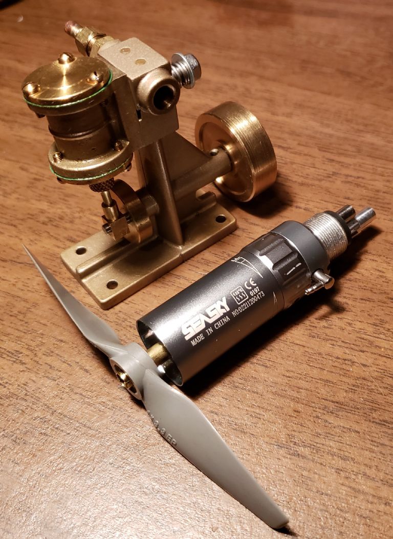
                                                I wanted to test a small vane type motor so I couldn’t resist purchasing the Seasky dental handpiece from Ebay shown in the following picture. The photo below it shows the modified Seasky air motor next to the MSM Tyne steam engine to illustrate its size. The size and cost of $17.59 seemed hard to beat. I will add some more information and the first test results in the next posts.

                                                seasky order.jpg

                                                seasky photo 2.jpg

                                                Edited By Turbine Guy on 21/12/2022 19:08:52

                                                #625692
                                                Turbine Guy
                                                Participant
                                                  @turbineguy

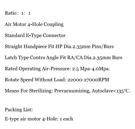
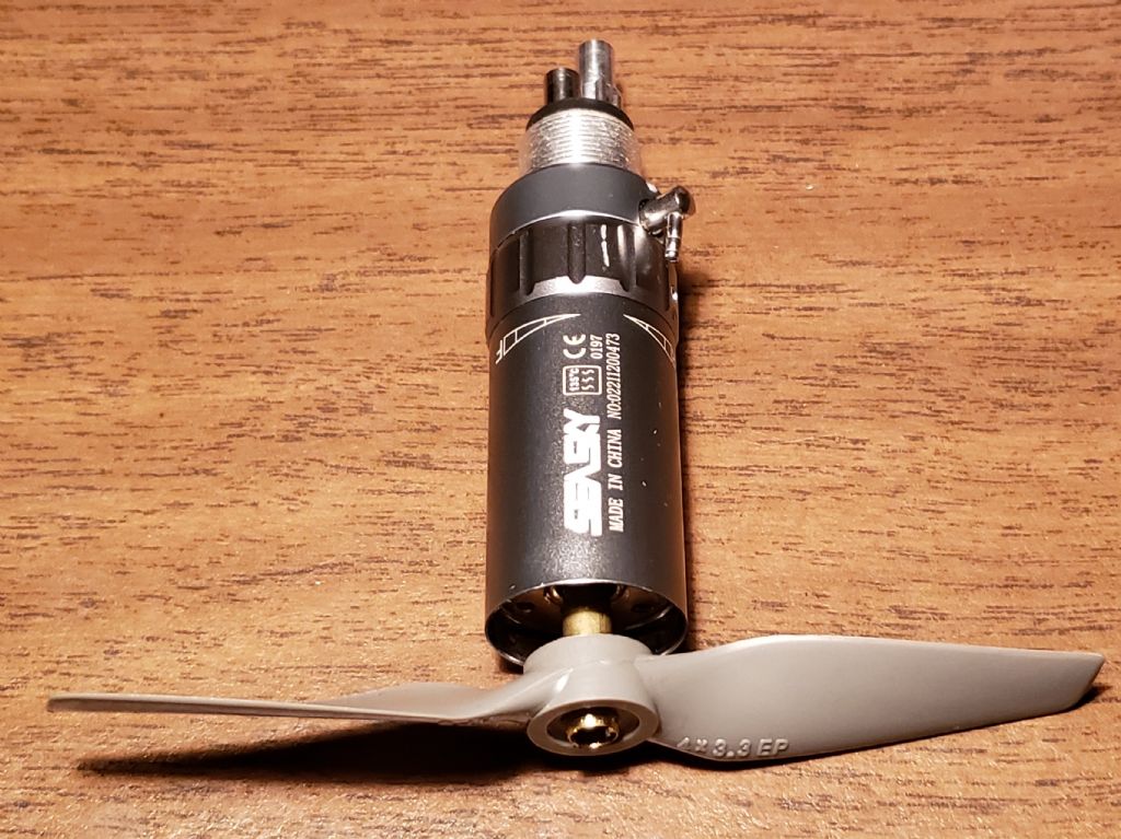
                                                  A copy of the specifications given for the Seasky handpiece is shown below. No model number or dimensions were given. The OD of the housing is 20mm. It was surprisingly easy to attach the propeller and add an enlarged extension to the air inlet tube as shown in the following photo.

                                                  seasky specs.jpgseasky photo 1.jpg

                                                  #625696
                                                  Turbine Guy
                                                  Participant
                                                    @turbineguy

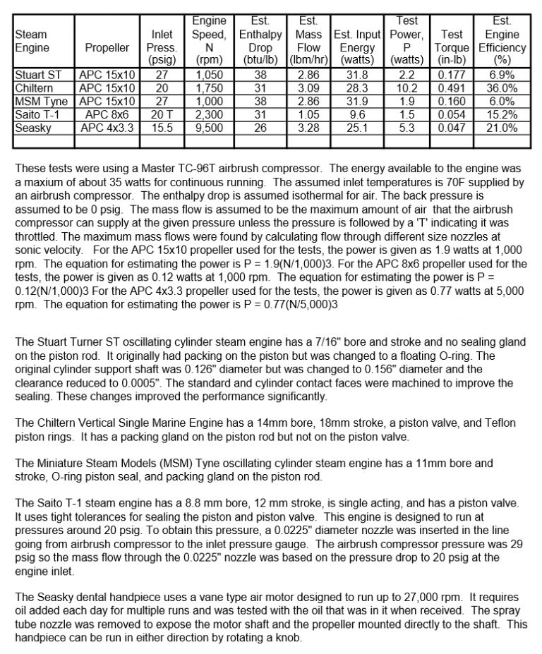
                                                    I added the first test results for the Seasky air motor shown below to the test sheet shown in the 22/07/2022 Post. The vane type air motor was very competitive with the Turbines and Engines I have tested at a surprisingly low cost.

                                                    my steam engines 6.jpg

                                                    #636951
                                                    Turbine Guy
                                                    Participant
                                                      @turbineguy

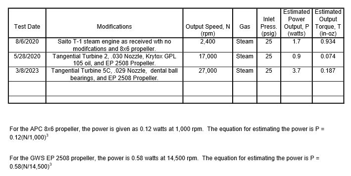
                                                      I added Radial Turbine 1 shown in the 09/01/2023 Post to my Model Turbines thread and Tangential Turbine 5C in the last posts since I last updated this thread. Tangential Turbine 5C had the best performance of all the turbines I have tested when running with the Stuart Twin Drum boiler. I added the performance of Tangential Turbine 5C to the test sheet shown in the 12/10/2020 Post of this thread. The following test sheet shows this update.

                                                      steam tests 3.jpg

                                                      Edited By Turbine Guy on 09/03/2023 20:28:11

                                                    Viewing 25 posts - 101 through 125 (of 125 total)
                                                    • Please log in to reply to this topic. Registering is free and easy using the links on the menu at the top of this page.

                                                    Advert

                                                    Latest Replies

                                                    Home Forums Stationary engines Topics

                                                    Viewing 25 topics - 1 through 25 (of 25 total)
                                                    Viewing 25 topics - 1 through 25 (of 25 total)

                                                    View full reply list.

                                                    Advert

                                                    Newsletter Sign-up