Testing Models

Advert

Testing Models

Home Forums Stationary engines Testing Models

Viewing 25 posts - 51 through 75 (of 125 total)
  • Author
    Posts
  • #396170
    Turbine Guy
    Participant
      @turbineguy

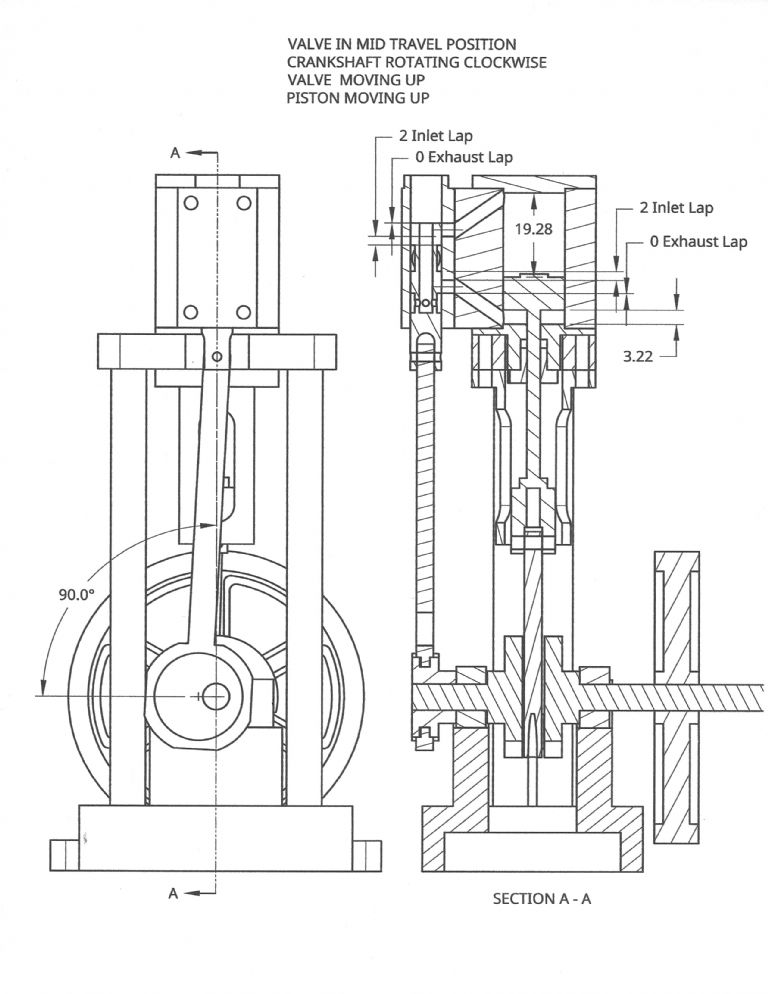
      I tried various combinations of inlet and exhaust lap for a single valve and found that an inlet lap of 2mm and no exhaust lap that gave an average cutoff of approximately 75% was the best combination for air with an available energy 17.5 watts. The air has an inlet pressure of 24 psig, a exhaust pressure of 0.0 psig, and a mass flow of 1.74 lbm/hr. The estimated output power is 5.6 watts. The estimated hydraulic efficiency is 51.8% and the estimated overall efficiency is 32.3%. Making a new valve without any other changes could increase the power by approximately 0.9 watts, a 19% improvement, and only require 1 new part.

      Valve 2 Mid Travel

      Advert
      #404534
      Turbine Guy
      Participant
        @turbineguy

        In the post of 31/12/2018 I stated: ‘The velocity coefficient for the existing rotor geometry, nozzle position and throat diameter, a power of 1.92 watts, an air flow of 1.74 lbm/hr, a inlet pressure of 24 psig, a inlet temperature of 70 F, and a speed of 17,012 rpm is 0.34. The velocity coefficient for the optimum Terry turbine rotor for these same conditions is 0.53.’ I built a rotor with twice the number of pockets of my first turbine rotor. The pockets of the new rotor overlap eliminating most of the edge blockage of the first design. I thought this design could possibly approach the performance of the optimum Terry turbine mentioned above. The following photo shows the new rotor (aluminum) next to the original rotor (brass). I tested this rotor with the same air pressure and flow used in the test of my original rotor that had a maximum speed of 17,000 rpm. The maximum speed with the new rotor was 18,250 rpm. The required power of the EP2508 propeller used in these tests is approximately 1.9 watts at 17,000 rpm and 2.4 watts at 18,250 rpm. The average rotor velocity coefficients for these output powers are 0.34 for 1.9 watts and 0.53 for 2.4 watts. I got the maximum I thought was possible, so this is a very significant increase. The original rotor has 24 pockets and the new rotor has 48 pockets. In Dr. Balje's study of high energy level, low output turbines the highest average rotor velocity coefficient for a Terry turbine with a single nozzle, 45 blades, and an admission length to rotor pitch length ratio of 1.72 was 0.53. The open pockets appear to be as efficient as the Terry turbine blades for this very small pocket size.

        Turbine Rotors

        #404538
        Turbine Guy
        Participant
          @turbineguy

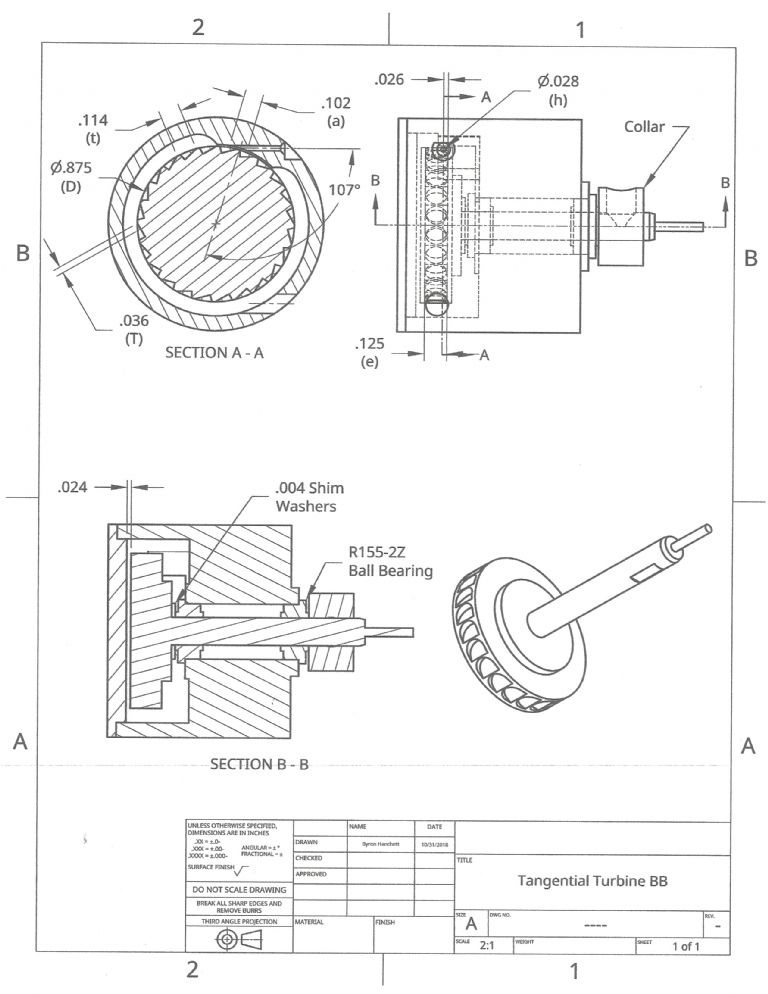
          The following drawing shows the details of the Tangential turbine of the previous post with the brass rotor.Tangential Turbine BB

          #404539
          Turbine Guy
          Participant
            @turbineguy

            The following drawing shows the details of the latest Tangential turbine with the aluminum rotor.

            Tangential Turbine 2

            #418414
            Turbine Guy
            Participant
              @turbineguy

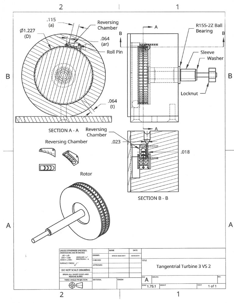
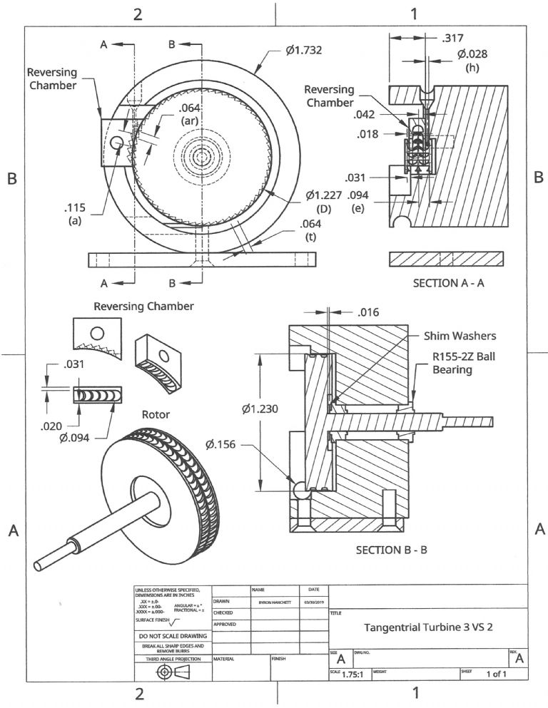
              I decided to make a velocity staged tangential turbine and the next few posts update the testing I have done.. The following drawing shows my initial design. Since I didn't get the first nozzle hole in the correct position I had to add another nozzle hole in the vertical position, but the concept is the same. . I designed this turbine to be able to run with the first row of blades only by leaving the reversing chamber off. The air or steam can exit the first row of blades out the opening required for the reversing chamber. I want to do this so that I can see the performance of the rotor with the larger diameter and greater number of pockets. The testing I have done on the last turbine indicates the open pocket design has about the same performance of a Terry turbine with the same rotor diameter, number of blades, nozzle admission length, and available energy. My first rotor with 24 pockets appeared to match the performance given by Dr. Balje’s diagram for Terry turbines with around 25 blades. My second rotor with 48 blades also matched the performance for Terry turbines with approximately 45 blades. The new turbine rotor has 60 pockets and the pocket angle has been reduced from 30 deg. to 25 deg so that the flow is closer to being perpendicular to the direction of rotation. Since the number of blades or pockets has a very large effect on the efficiency, I expect my new turbine running with just one row of blades and a larger diameter to further improve the performance even with the rotational losses of two rows of blades.. Tangential Turbine 3 VS 2A

              #418422
              Turbine Guy
              Participant
                @turbineguy

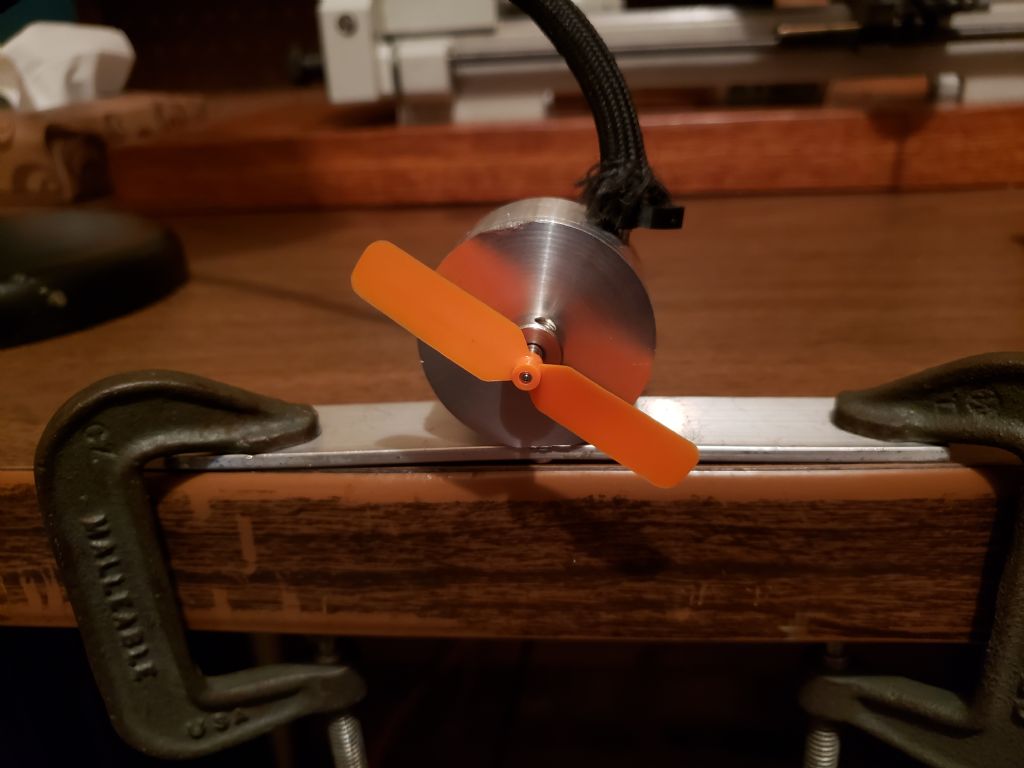
                I ran my new turbine without the reversing chamber with my airbrush compressor and it obtained a speed of 21,500 rpm turning the EP2508 propeller. My estimation of the power required by this propeller to turn at that speed is 3.8 watts. The power available to the turbine from my airbrush compressor is approximately 18 watts so the efficiency is approximately 21.9%. This is an increase in power of about 1.5 watt over what was obtained by my last turbine for the same amount of energy. The increase in power is primarily due to the increase in rotor diameter, increase in number of pockets, and reduction of the pocket inlet angle. The increase in the rotor diameter was from 0.892 in. to 1.226 in. This increases the rotor tip speed and torque. The increase in rotor tip speed raises the power but also increases the rotational (windage) loss. The rotational loss is still low enough at 21,500 rpm that even with the extra set of pockets it did not appear to be excessive. The increase in number of pockets was from 48 to 60. With single nozzles, the number of pockets under the nozzle discharge opening becomes very important since energy is lost in filling the empty pockets. The pocket inlet angle decreased from 30 degrees to 25 degrees. The smaller the angle, the less energy is lost from the flow not being perpendicular to the direction of travel. The power achieved was greater than expected so my estimations of power from the propeller might not be conservative. However, the increase in performance with each of the changes using the same propeller and airbrush compressor verifies that Dr. Balje’s guidelines are useful in the design of model turbines.
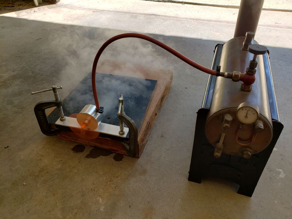
                The following photo shows my test setup.
                Tangential Turbine 3 VS Test

                #418424
                Turbine Guy
                Participant
                  @turbineguy

                  I also ran my new turbine on saturated steam at a gage pressure of 50psi (3.4 bar) and an estimated water rate of 0.55 oz./min. The maximum speed it turned the EP2508 propeller was 28,000 rpm. The estimated power required for the EP2508 propeller at this speed is approximately 8.6 watts. The steam was supplied by a Stuart Turner model 504 boiler and the assumed temperature was for saturated steam at the inlet pressure. I assumed the modest superheat of this boiler was lost to the cold turbine housing with air from the propeller blowing over it. The following photo shows the test setup.Tangential Turbine 3 VS Test 2

                  #418425
                  Turbine Guy
                  Participant
                    @turbineguy

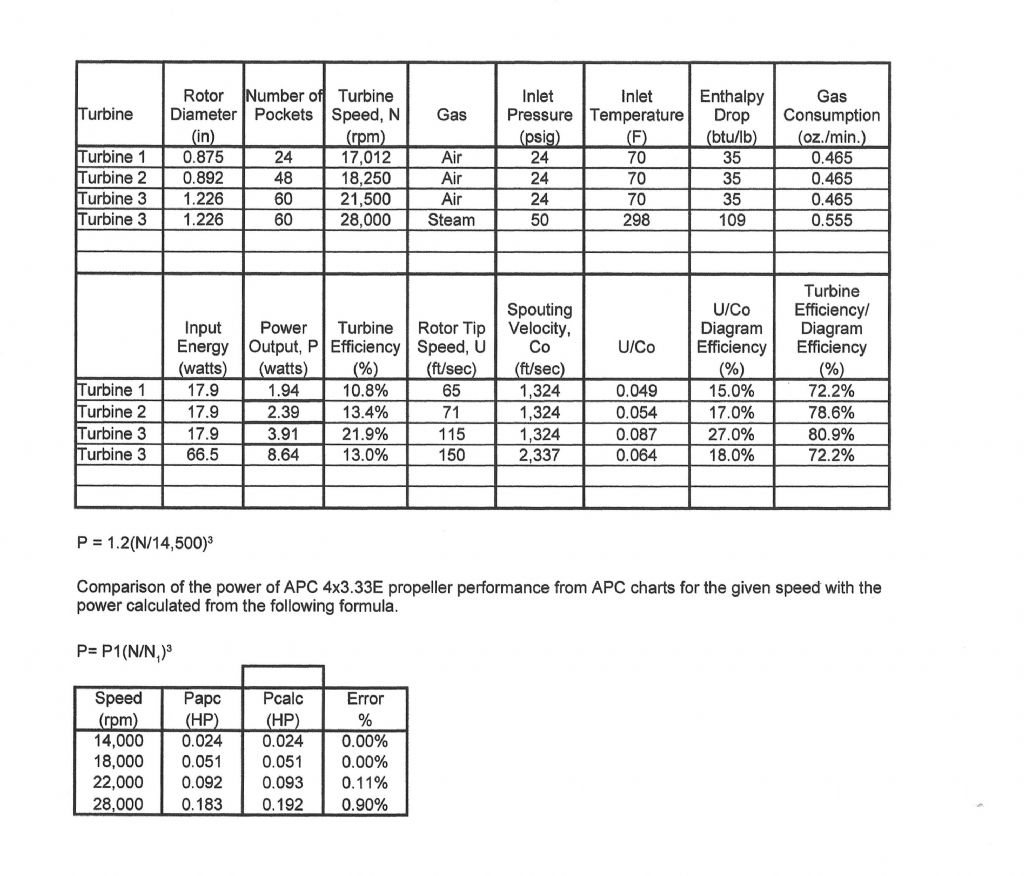
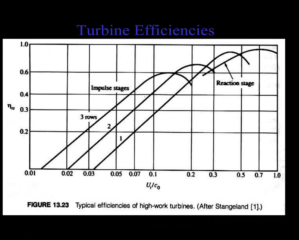
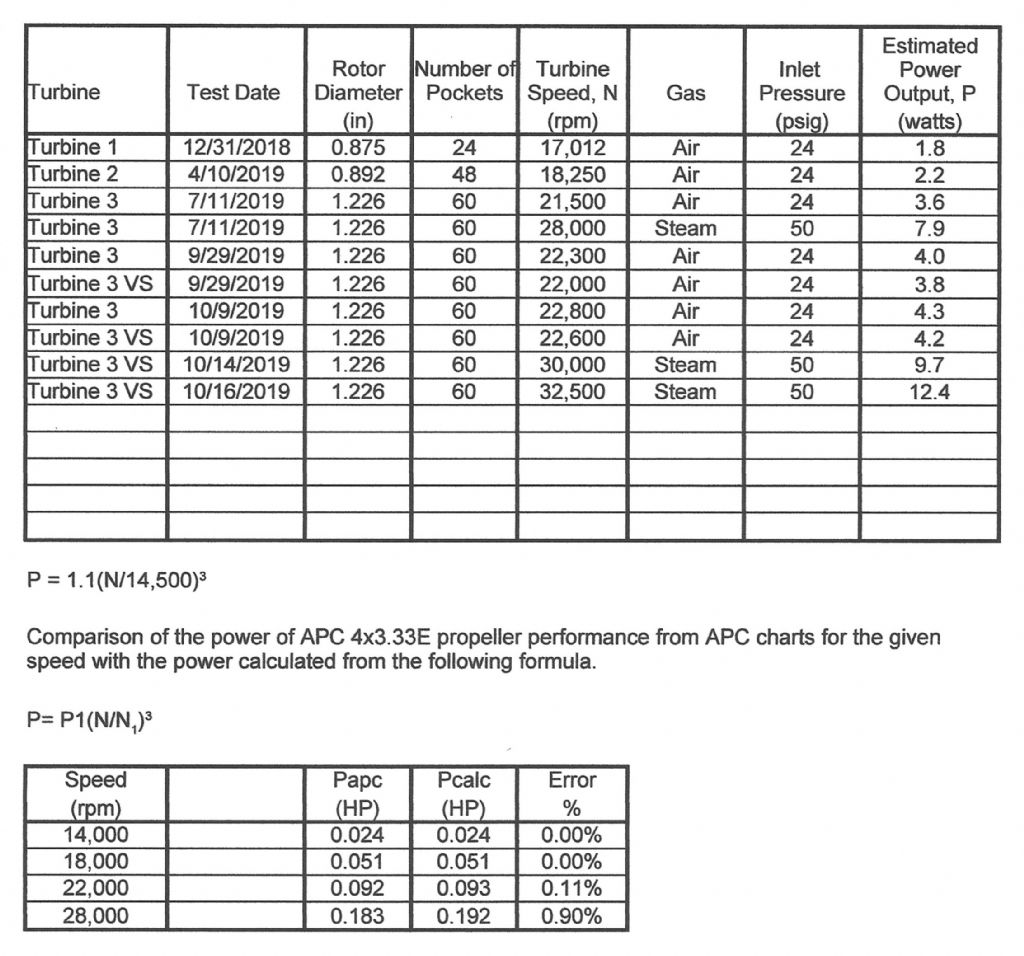
                    I made the following chart to summarize the testing of my turbines and a chart at the bottom to check the validity of my equation for estimating the power required by the EP2508 propeller. I had only one speed of the EP2508 propeller that I could verify the required power. I wanted to see if my use of increasing the propeller power by the cube of the turbine speed was valid for the range of speeds of my tests. Since APC has performance charts for all its propellers, I checked the performance of their propeller closest in size to my EP2508 propeller at the speeds nearest to the speeds obtained in testing. As shown in the chart, increasing the power by the cube of the speed for the range from 14,000 to 28,000 rpm was accurate to within 1%. Since the first test was with Rulon bushings and run with a smaller boiler, I did not include its performance in this chart. This way all the tests on air or steam will be with the same airbrush compressor or boiler and all the turbines have the same ball bearings. I also added a comparison of the efficiency of my model turbines with the efficiencies of high duty axial turbines shown on the U/Co diagram that will be added in the next post. I added this to show under similar conditions, even the optimum axial turbines do only approximately 20% better than my optimized open pocket tangential turbine.My Turbines 3

                    #418426
                    Turbine Guy
                    Participant
                      @turbineguy

                      The following chart shows the efficiency of high duty turbines as a function of the velocity ratio of the rotor tip speed U to the ideal spouting velocity Co. This chart assumes turbine stages with enough nozzles, tight clearances, and power to make the filling losses and rotational losses negligible.Turbine Efficiencies

                      #418436
                      not done it yet
                      Participant
                        @notdoneityet

                        Interesting. ‘Estimates’ to three significant figures. How do you manage to measure the power to even a precision of one in five hundred, let alone an accurate figure, to three sig figs? Just wondering – from a mathematical view-point.

                        #418535
                        Turbine Guy
                        Participant
                          @turbineguy
                          Posted by not done it yet on 12/07/2019 06:43:06:

                          Interesting. ‘Estimates’ to three significant figures. How do you manage to measure the power to even a precision of one in five hundred, let alone an accurate figure, to three sig figs? Just wondering – from a mathematical view-point.

                          Very good point. I explained how I assumed a power of 1.2 watts for the EP2508 propeller turning at 14,500 rpm at the beginning of this thread. And later explained how the actual accuracy of the 1.2 watts was not as important to me as the change in power with each modification to my turbines. That being said, an accuracy of two significant places should have been used for the values of power. Thanks for pointing this out.

                          #431283
                          Turbine Guy
                          Participant
                            @turbineguy

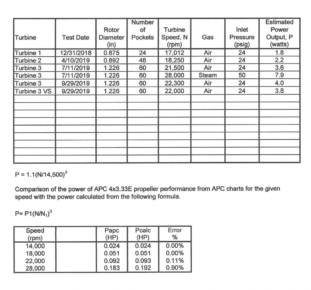
                            I made the following chart to summarize the testing of my turbines. I lowered the estimated powers in this chart slightly from what I have previously given to be more conservative. These values of power are approximately the power I calculate using Dr. Balje’s guidelines. The first test with velocity staging resulted in lower power than with the reversing chamber removed. This is comparing an optimized single stage with the first try of velocity staging. Hopefully by optimizing the reversing chamber I can improve the performance of the velocity staging. The next post gives the updated drawing that is the first revision for turbine 3 with the velocity staging. As you can see there are quite a few changes from the drawing shown in the post of 11/07/2019. Some changes were made to improve the design while others were to repair errors in machining. This drawing shows the dimensions important for setup and analysis and shows the actual part dimensions at the time of this revision. Turbines Test Results

                            #431284
                            Turbine Guy
                            Participant
                              @turbineguy

                              The followings is the drawing I described in the last post.

                              Tangential Turbine 3 VS A

                              #434118
                              Turbine Guy
                              Participant
                                @turbineguy

                                I ran several tests with air to find the maximum performance. These tests are described in the Model Turbines thread and summarized in this and the following posts. The improvement in performance running on air was very small. The speed increased by 500 rpm without the reversing chamber and 600 rpm with the reversing chamber with the improvements. The turbine still made slightly more power without the velocity staging running on air. Apparently, the back pressure caused by the second stage was enough to keep the performance from getting better than with a single stage. I ran the velocity staging with steam on 14/10/2019 and added the performance of this test to the table. The extra energy of the steam allowed the velocity staging to work better. The boiler pressure was the same as the test of 11/7/2019 without velocity staging, so the energy supplied should be approximately the same. The velocity staging with steam got a 1.8 watt increase in power. I planned on running on air immediately after running on steam to see if that would keep the ball bearings from gumming up. Even after releasing the hose clamp, the silicon hose I used for steam would not come off. I pressed the hose from my airbrush compressor against the silicon hose and got enough pressure to spin the turbine and blow the water out. I then tried pulling as hard as I could on the silicon hose. The stainless steel (ss) tube that was Loctited to my turbine housing popped out. I had to cut the silicon hose to remove it from the ss tube. I don’t know what caused the silicon hose to bond to the ss tube. I Loctited the ss tube back on my turbine housing and will run the turbine on air after the Loctite cures. Hopefully, the ball bearings will not gum up.

                                #434119
                                Turbine Guy
                                Participant
                                  @turbineguy

                                  I ran Turbine 3 on air after Loctiting the stainless steel inlet tube back on the housing. The speed never got back to the speed the turbine was running with the reversing chamber installed but my airbrush compressor was shutting down periodically. This indicated the turbine nozzle was partially blocked. I cleaned out the nozzle and ran the turbine on air again. The speed of the turbine went back to the same maximum speed it had before with velocity staging. Running the turbine on air immediately after running on steam appears to keep the ball bearing oil from gumming up. I wasn’t sure if the blockage in the nozzle occurred before or after the run on steam so I ran the turbine on steam again. After cleaning out the nozzle, Turbine 3 reached a maximum speed of 32,500 rpm with velocity staging. The resulting power of 12.4 watts was about what I hoped I would be able to achieve with velocity staging. This is an increase in power of approximately 4.5 watts with velocity staging. This increase in power is a little misleading. It should be pointed out that if the turbine was turning a load that could be adjusted, the power without velocity staging of Turbine 3 would be around 11 watts at 32,500 rpm. The power added by the velocity staging would be approximately 1.5 watts compared with the power that could be achieved at this speed without velocity staging. Using a propeller for the load results in the speed being set by the torque required to turn the propeller. The speed was very consistent during the short run on steam. Also, the relief valve on the boiler was constantly releasing steam so the pressure of 50 psig (3.4 bar) was the maximum the boiler could produce. I ran Turbine 3 on air after the run on steam and the maximum speed obtained was 22,600 rpm so the friction of the ball bearings has not changed. I am very pleased with the performance of Turbine 3 running on steam with velocity staging. The following chart is updated to show all the tests.

                                  Turbines Test Results 3

                                  #434121
                                  Turbine Guy
                                  Participant
                                    @turbineguy

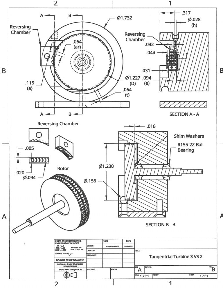
                                    The following drawing shows some of the important dimensions of my Turbine 3 after getting the best performance I was able to obtain with velocity staging. Making the outer edge of the reversing chamber as thin as possible made the biggest improvement. This opened up the space for the steam or air exiting the second stage. I was able to meet all my goals with these last tests so I don't plan on any further testing of Turbine 3.

                                    Tangential Turbine 3 VS B

                                    #434810
                                    Turbine Guy
                                    Participant
                                      @turbineguy

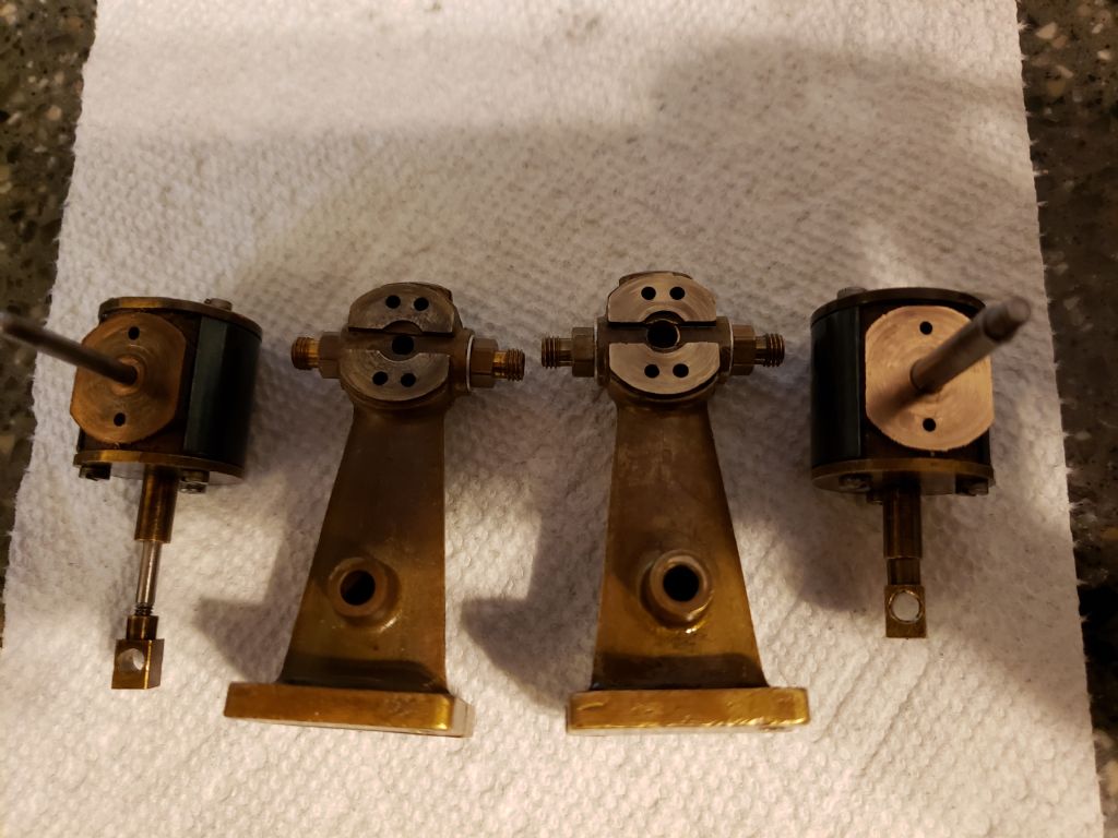
                                      Since I was able to achieve the performance I hoped to obtain with my turbines, I decided to work on my Stuart Turner St oscillating steam engines again. The following photo shows the machining done on the cylinder and standard of the parts on the right and the same parts without modification on the left for comparison. I machined the mating faces of the standard and cylinder on the parts on the right. As I suspected, the mating surfaces were worn conical by the tilting back and forth of the cylinder as the engine ran. You can also see in the photo how much larger the cylinder support shaft is on the parts on the right side. The following is the speeds I posted 1/7/2019 after running the APC 8×6 propeller with the enlarged cylinder support shaft. The maximum speeds for 5, 10, 15, and 20 psig were 450, 655, 765, and 851 rpm respectively. After machining the faces, the maximum speeds for 10, 15, 20, and 24 psig were 1,000, 1,125, 1,215, and 1,450 rpm respectively. I was able to maintain a pressure of 24 psig after machining the faces. 20 psig was the maximum I could maintain before machining the faces. After testing I took the cylinder off and tried moving the piston with the ports open and closed. There was only a slight increase in force moving the piston with the port closed so the packing loosened up from the previous tests. For propellers, the power goes up by the cube of the speed so the increase in performance was substantial. In the next post I’ll add a chart similar to the one I used for documenting the testing of turbines.

                                      ST Parts

                                      #434815
                                      Turbine Guy
                                      Participant
                                        @turbineguy

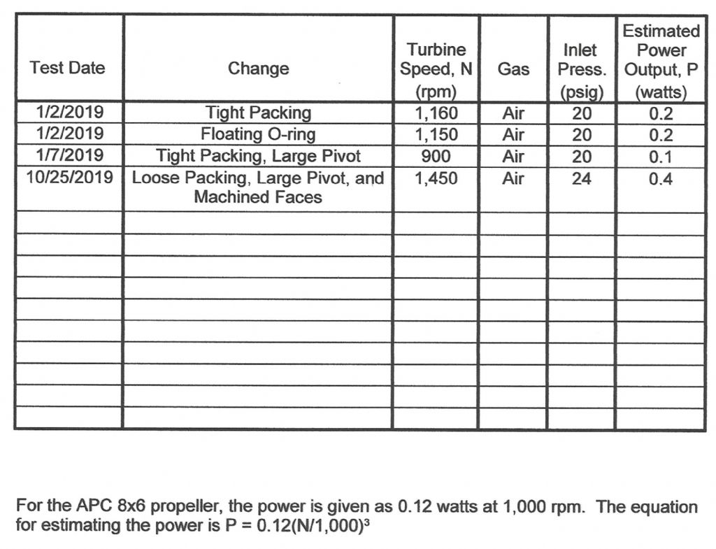
                                        The following chart shows the maximum estimated powers my Stuart Turner ST oscillating steam engine has produced in all the tests I have made so far. The dates in the table are with the month first, day second, and year third as we use in the USA. This chart gives only the maximum estimated powers obtained on the given dates for the changes to the engine shown. Posts in this thread near the dates shown have quite a bit of additional information. I am still trying to find out why the amount of power obtained is so low for this engine. I have tried to be very careful in the changes I've made but maybe I have done something that causes this. The loose packing is allowing more leakage but the power has increased over what was produced with the tight packing due to the mating faces of the cylinder and standard being flat now. I'm going to try using the floating O-ring next.

                                        ST Test Results

                                        #438247
                                        Turbine Guy
                                        Participant
                                          @turbineguy

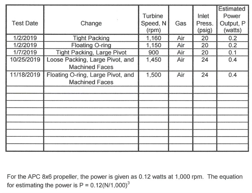
                                          The following is the speeds I posted 10/25/2019 running the APC 8×6 propeller after machining the faces. The maximum speeds for 10, 15, 20, and 24 psig were 1,000, 1,125, 1,215, and 1,450 rpm respectively. After switching to the floating O-ring, the maximum speeds for 10, 15, 20, and 24 psig were 1,000, 1,250, 1,400 and 1,500 rpm respectively. I was able to maintain a pressure of 24 psig after machining the faces, 20 psig was the maximum I could maintain before machining the faces. After testing I took the cylinder off and tried moving the piston with the ports open and closed. The force to move the piston was very large with the port closed when moving toward the top cylinder cover. The force was quite a bit less with the port closed and moving toward the bottom of the cylinder due to leakage around the connecting rod. There was very little force required to move the piston in either direction with the ports open. Even with the much tighter clearance on the cylinder support shaft, the cylinder is pried away from the standard if the pressure is above 15 psig (1 bar). This only happens with the tight packing or floating O-ring. Tightening the spring to the maximum doesn’t keep the cylinder from being pried away. I believe the biggest weakness of the simple oscillating cylinder engines is the cylinder pin riding in a hole on one side only. If the seal is good on the piston, the force cocking the cylinder can be very large. If you make the spring large enough to keep the face of the cylinder from being pried away from the face of the standard, the friction loss becomes too large. From my testing with a relatively tight clearance on the cylinder pin, the best power came with the spring compressed less than the maximum. The flow lost by the cylinder cocking was still relatively low because of the tight clearance. The cylinder would tilt away from the standard each time the pressure was above 15 psig. This caused a leakage at higher pressures that limited the power. My airbrush compressor had to run continuously at pressures above 15 psig but could maintain pressures below 15 psig by running intermittently. Apparently, the friction and binding caused by the increased pressure partially offsets the gain in performance from having less leakage by the piston.

                                          The following chart has been updated to show the tests with the floating O-ring and shows the maximum performance was about the same for the floating O-ring and bedded in packing.
                                          ST Test Results 2

                                          #439437
                                          Turbine Guy
                                          Participant
                                            @turbineguy

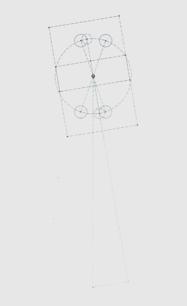
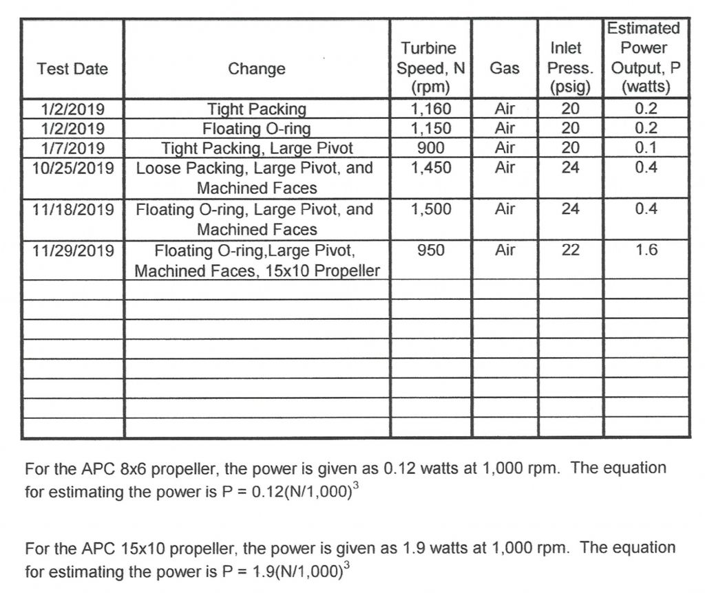
                                            I kept looking for reasons my Stuart ST oscillating steam engine was putting out such low power. I analyzed the flow through the ports with the small opening area. The following diagram shows the ports in the maximum opening position. The circles with the solid lines represent the holes in the standard. The dashed circles represent the holes in the rotating cylinder. As you can see the maximum overlap is very small. The hole in the rotating cylinder is 1/16 inch in diameter and the full flow area is 0.0031 square inches. The maximum opening area of the overlapped ports is 0.0013 square inches. The average opening area during the intake cycle is 0.00084 square inches. I estimated the pressure drop in the inlet and exhaust ports to fill and empty the cylinder at 1500 rpm with the average opening area. The estimated inlet pressure drop was 3.7 psi and the estimated exhaust pressure drop was 8.3 psi. With half the available pressure lost in filling and emptying the cylinder at 1500 rpm, I thought running at a lower speed would be more efficient. I removed the APC 8 x 6 propeller and mounted an APC 15 x 10 propeller. The maximum speed I was able to obtain with the 15 inch propeller was 950 rpm. The power required by the APC 15 x 10 propeller at that speed is 1.6 watts. This is a major increase in power from my previous tests and is more like I expected from the Stuart ST steam engine. Apparently, it is best to run at a low speed due to the very small port opening area. I will add an updated chart including this test in my next post.

                                            ST Port Opening

                                            Edited By Turbine Guy on 29/11/2019 21:13:22

                                            #439439
                                            Turbine Guy
                                            Participant
                                              @turbineguy

                                              The following chart shows the test described in the last post. 22 psig was the maximum pressure I could obtain with my airbrush compressor running continuously with the APC 15 x 10 propeller.

                                              ST Test Results 3

                                              #439507
                                              Neil Wyatt
                                              Moderator
                                                @neilwyatt

                                                Thanks for these Turbine Guy, interesting stuff.

                                                Aeromodeller used to have a special set of props they used to test engines!

                                                Neil

                                                #439529
                                                Turbine Guy
                                                Participant
                                                  @turbineguy
                                                  Posted by Neil Wyatt on 30/11/2019 16:00:20:

                                                  Thanks for these Turbine Guy, interesting stuff.

                                                  Aeromodeller used to have a special set of props they used to test engines!

                                                  Neil

                                                  Thanks for your kind remarks. I love using the APC propellers. They're not very expensive, have performance charts for each propeller, and are designed to use the same adapter. I'm so used to trying to run my model turbines as fast as I can, it took me a while to realize steam engines normally work best at low speeds. I think Stuart Turner might have purposely limited the intake opening on their oscillating engine to keep it from running fast enough to hurt itself. With the relatively high friction and very small port opening area, I doubt the runaway speed without a load is very high.

                                                  #442819
                                                  Turbine Guy
                                                  Participant
                                                    @turbineguy

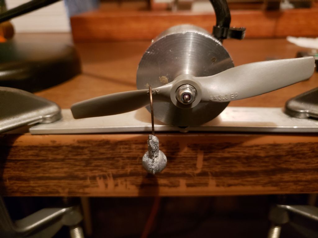
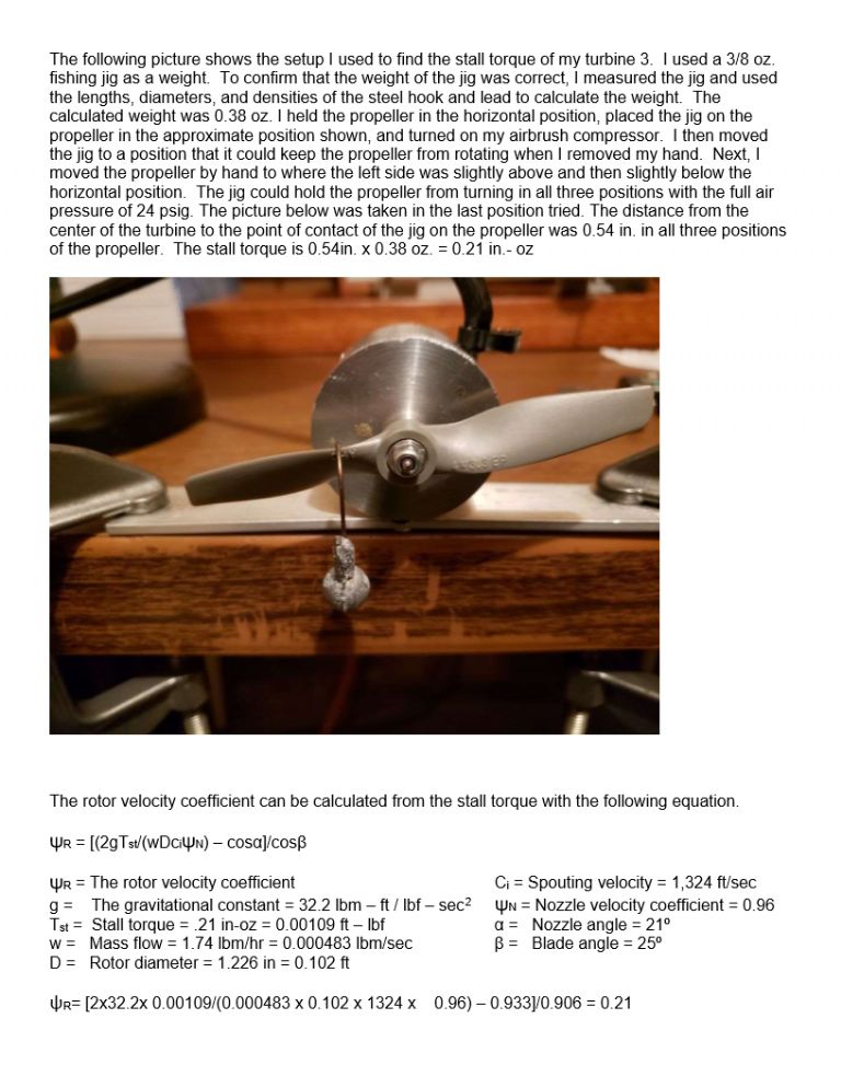
                                                    The following photo shows the test setup I used to find the stall torque of my turbine 3. The description of the test and the results are given in this link. https://www.model-engineer.co.uk/forums/postings.asp?th=140195. This is a very simple and accurate way to find the stall torque.

                                                    Torque Test

                                                    #443023
                                                    Turbine Guy
                                                    Participant
                                                      @turbineguy

                                                      The following jpeg files show the description of the test and results mentioned in the last post. Since so many things effect the rotor velocity coefficient, I thought a full description of this simple accurate method to determine it's actual value would be useful.

                                                      Turbine 3 Hyd. Power 1

                                                    Viewing 25 posts - 51 through 75 (of 125 total)
                                                    • Please log in to reply to this topic. Registering is free and easy using the links on the menu at the top of this page.

                                                    Advert

                                                    Latest Replies

                                                    Home Forums Stationary engines Topics

                                                    Viewing 25 topics - 1 through 25 (of 25 total)
                                                    Viewing 25 topics - 1 through 25 (of 25 total)

                                                    View full reply list.

                                                    Advert

                                                    Newsletter Sign-up