Testing Models

Advert

Testing Models

Home Forums Stationary engines Testing Models

Viewing 25 posts - 26 through 50 (of 125 total)
  • Author
    Posts
  • #389745
    Tim Taylor 2
    Participant
      @timtaylor2
      Posted by Turbine Guy on 06/01/2019 16:08:30:

      Tim,

      It looks like you picked a very good turbine to base your design on. I searched on the internet for information on this turbine and found the following for a rebuilt turbine. They didn't give the temperature or the mass flow of the steam for this power. It surprised me the turbine would operate at such a low speed.

      Specifications

      Coppus Steam Turbine TF-9

      RPM: 1250

      HP: 0.75

      Inlet PSIG: 75

      TG,

      The Coppus TF design dates back to the 1920's. 15 psig is on the low side of inlet pressure – depending on materials of construction they could operate up to 650psig/750F steam with back pressures up to 150psig, and could produce up to 1000bhp. They also had a vertical version of the design…

      In the 1970's the TF design was superseded by the RLA design, which changed from a flyball governor to a woodward oil relay governor and a new safety trip design. In the 1980's a horizontally split design called the RLH was introduced. Coppus is now part of Dresser. The following link is to a brochure describing the various designs – you might find it of interest.

      http://www.mercado-ideal.com/catalogosd/DRESSER-RAND%20COPPUS%20STEAM%20TURBINES.pdf

      The one I am going to model is actually similar to one of the horizontally split designs – both have similar wheels.

      Tim

      Advert
      #389881
      Turbine Guy
      Participant
        @turbineguy

        I’ve run the ST engine with the tight packing and the increased cylinder shaft size off and on for about a half an hour and the maximum speed is up to about 900 rpm now. Since my airbrush compressor is able to maintain a pressure of 20 psig at the maximum speed the engine is running and the power output is very low, I tried to estimate the power losses. I looked at the friction power loss at each of the motion points and estimated the total power loss due to friction is approximately 2.68 watts. I use a friction coefficient of 0.3 for the analysis. I estimated the pressure drop in the inlet port to be 1 psi. I estimated the pressure drop in the exhaust port to be 4 psi. With these pressure drops, the existing clearance volumes, and the cut off point of the ports I calculated the mean effective pressure. I estimated the mean effective pressure to be approximately 15 psi and the corresponding indicated power to be 3.25 watts. Subtracting the friction power loss from the indicated power gave a power output of 0.57 watts. The power required to turn the 8” propeller 900 rpm is 0.09 watts. My calculations don’t quite show where all the power was lost but confirm that the power loss due to friction and pressure drop through the ports is very high for the Stuart ST engine. The lower speed with the increased cylinder shaft size is partially explained by the engine not being fully broken in. In addition, the friction loss of this shaft goes up in direct proportion with the increase in shaft diameter. The low power output is finally starting to make sense.

        #390101
        Turbine Guy
        Participant
          @turbineguy

          I found an error in my calculations for the power output of my ST engine. The corrected total power loss due to friction is approximately 2.55 watts and the resulting calculated power output is 0.7 watts. This leaves a little more loss unaccounted for, but the result is about the same. In my calculations I used the friction given by Parker for a floating 0-ring even though I ran the last tests with the tight packing. I needed some method to calculate the friction when the seal gets pressed against the cylinder bore by pressure. Since I got almost identical performance with the 0-ring and the tight packing in earlier tests I thought this method was valid for either. The only unknown in the rest of the calculations is the friction coefficient. This varies with the materials used, the finish, and whether dry or lubricated. The value of 0.3 I used for the friction coefficient is what I have seen used before for estimating the friction. Because of these unknowns the calculations are only indicative of the approximate size of these losses.

          #391805
          Turbine Guy
          Participant
            @turbineguy

            I purchased a Chiltern Vertical Single Marine Engine. This engine has a 14mm bore, 18mm stroke, a piston valve, and Teflon piston rings. I ran my Chiltern engine for a short time and very quickly it was able to run on 5 psig (0.34 bar) air pressure. I checked the leakage holding the valve in various positions with maximum pressure. When the valve was in the position that both ports were closed there was very little leakage after the engine had been run for a few minutes and not reoiled. After I oiled the engine the leakage completely stopped in this position. This was with a pressure of 24 psig (1.63 bar), the maximum I plan to use. When I moved the valve to a position that the ports were open, the leakage started but did not seem excessive. The leakage was about the same in all positions of the valve accept at each end of its travel where it increased quite a bit. These positions are where the distance from the edge of the port to the edges of the inlet and outlet are shortest. Apparently, the valve clearance is tight enough that oil can seal it in most positions. Even after running a while the valve leakage only increased a little. The piston rings have some leakage but it doesn't appear to be excessive. The minimum pressure the engine would continue to run stayed at about 5 psig (0.34 bar). Each time I shut the compressor off when the engine was running, the speed increased before slowing down and stopping. I'm still trying to figure out what causes this. I'll add a photo of this engine in the next post.

            #391807
            Turbine Guy
            Participant
              @turbineguy

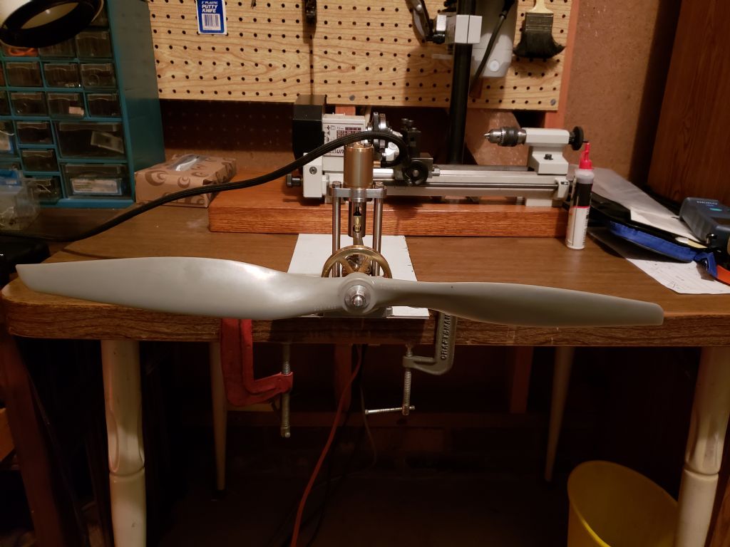
              I like using the propellers for a load since I can get the amount of power they require for a given speed. For a small air compressor and medium size engine, I have to use a very large propeller to keep the speed low. If I use a small propeller, my compressor can't keep up with the flow required and the pressure drops. With a 14mm bore and 18mm stroke, my Chiltern engine requires the maximum output of my airbrush compressor to maintain a pressure of 24 psig (1.63 bar) at a speed of 675 rpm with no leakage. With leakage, the speed will be even lower to maintain this pressure. I bought a 22" (560mm) diameter propeller for testing this engine. The propeller is a APC 22 x 12 WE It is 22" diameter propeller with a 12" pitch and requires about 14 watts to run at 1000 rpm. I show this propeller mounted to the Chiltern steam engine below. There is also a couple of pictures of the Chiltern steam engine without the propeller mounted in my album. I would appreciate it if someone could tell me how rotate the pictures in the album to the position they should be viewed.Chiltern with propeller

              #391910
              Turbine Guy
              Participant
                @turbineguy

                I attached the propeller to the engine, mounted the engine on a plate, clamped the plate to my workbench, and turned on the airbrush compressor. The propeller spun at a maximum speed of 700 rpm with a pressure of 20 psig (1.36 bar). The power required by the propeller at this speed is approximately 4.71 watts. The amount of air required by the engine to fill the cylinder at this speed and pressure is approximately 1.52 lbm/hr. Since my airbrush compressor is only capable of about 1.74 lbm/hr, the total leakage was very small. I was very pleased with the Chiltern engine. It did better than I thought it would. The energy available from the airbrush compressor is approximately 16 watts, so I would like to determine where the losses come from. With steam engines, friction, pressure loss through the ports, and leakage can all be major parts of the loss and are difficult to estimate. In addition, using the full pressure for almost the entire stroke (almost no cutoff) wastes quite a bit of energy. Also, the Chiltern engine has relatively large clearance volumes that waste some energy. I’ll see if I can estimate where the major losses came from.

                #391932
                Turbine Guy
                Participant
                  @turbineguy

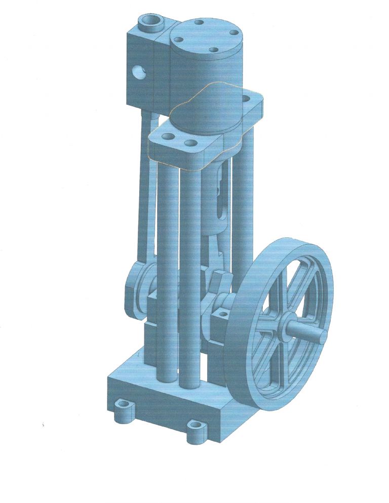
                  To estimate where the losses came from, I started with the best case. I estimated the indicated power without any pressure drop through the ports, no clearance volume, full expansion, and no compression of the steam on the exhaust cycle. This is a perfect condition where the power produced equals the energy available. I used a 14mm bore, 18mm stroke, air with an inlet pressure of 20 psig, an exhaust pressure of 0.0 psig, and a mass flow of 1.74 lbm/hr. With these conditions, the power is approximately 16 watts at a speed of 1,660 rpm. I kept everything the same except adding the Chiltern’s actual clearance volume of 0.028 in^3. With only the clearance volume added, the power dropped to 11.7 watts at a speed of 1,250 rpm. The actual clearance volume causes a reduction in power of approximately 4.3 watts. The Chiltern’s clearance volume is so large primarily due to the clearance between the piston and cylinders at each end of travel being 2.25mm (0.089 in). I used the Onshape solid model shown below to find the clearances and other dimensions needed for analysis. The solid model has the parts mated with the same degrees of freedom as the actual engine. Turning the flywheel in the solid model moves the parts the same as they would in the Chiltern engine.Solid Model of Chiltern

                  #392120
                  Tim Taylor 2
                  Participant
                    @timtaylor2

                    TG,

                    Might be a stupid question, but is your 20 watt estimate based on compressor input power or net output? Compressors are notoriously inefficient, typically 50% or less – a lot of the energy is lost as low grade heat from the heat of compression.

                    Tim

                    #392127
                    Tim Taylor 2
                    Participant
                      @timtaylor2

                      sorry….16 watts…..

                      #392132
                      Turbine Guy
                      Participant
                        @turbineguy

                        Tim,

                        When I decided to use the airbrush compressor for my testing, I connected the compressor to my turbine to find the maximum pressure I could run with all the air going through the turbine nozzle. I found the maximum pressure was 24 psig and the turbine temperature was approximately 70 F. For this pressure, temperature, and .028” nozzle throat diameter the theoretical mass flow is approximately 1.74 lbm/hr. For this temperature, pressure, and mass flow the energy available to the turbine is approximately 18 watts. This is my assumed maximum output for my airbrush compressor when running the turbine.

                        #392135
                        Turbine Guy
                        Participant
                          @turbineguy

                          The 16 watts maximum for the engines was found the same way. 20 psig was the maximum pressure the airbrush compressor could maintain with the engines which lowered the available power to 16 watts.

                          #392142
                          Tim Taylor 2
                          Participant
                            @timtaylor2

                            TG,

                            That answers my question.

                            Regarding efficiency, I think you have a couple things going on that may be throwing you a curve.

                            First, there is a big difference between D&S steam and compressed air – steam has roughly 8 times the enthalpy of compressed air at the same pressure & temperature. Steam is not an ideal gas, and steam engines are designed to take advantage of the isentropic enthalpy drop and the expansion characteristics of steam. The valve timing for steam, for example, is not what would be the most efficient for compressed air. A steam engine running on air will not be as efficient as if it were running on steam.

                            Second are the leakage paths you have already mentioned. Design clearances take into account thermal expansion at operating temperature, and what may be a significant leak at room temp, will not be at designed operating temperature.

                            Was your clearance volume in in^3 or cm^3? Based on your 14mm bore by 18mm stroke, I calculated the swept volume as 2.77 cm^3. The optimum clearance volume is typically around 10% of the total volume, so if your clearance volume is in cm^3, then it's in the ball park.

                            I find your progress quite interesting – please keep us posted………

                            Tim

                            Edited By Tim Taylor 2 on 20/01/2019 22:13:48

                            #392160
                            Turbine Guy
                            Participant
                              @turbineguy

                              Tim,

                              I agree with your comments about the difference in using steam and air and testing the engine with air when it was probably designed for steam. What I am trying to determine is where the losses come from for the tests I've made with air. The actual amount of these losses would be different for steam, but I chose air since it eliminates one of the major difficulties. With steam, condensing can occur if the steam does not have enough superheat or the engine hasn't been run very long. The amount of moisture in the steam is very difficult to determine and has a big effect on the performance. With air and a compressor with very low output, the change in temperature is very small and the process is basically isothermal rather that isentropic. I can't tell the difference in temperature between the outlet of my airbrush compressor and the outlet of my engine even after a long run. I use the formulas for isothermal expansion of air to determine the enthalpies. I agree my findings are only valid for running the Chiltern engine on air, but should give a reasonable indication of the magnitude of the losses.

                              The actual clearance volume of the Chiltern engine I gave was 0.028 cubic inches or 0.459 cubic centimeters. This is 16.5% of the swept volume.

                              Sorry I use different measuring systems. All my calculations use English units. The Chiltern engine is metric so I made my solid model metric and when I pull dimensions off the model they are in millimeters which I usually convert to inches

                              Thanks for your feedback..

                              #392232
                              Turbine Guy
                              Participant
                                @turbineguy

                                To estimate the loss due to the long cutoff for the Chiltern engine, I started again with the ideal case. I estimated the indicated power without any pressure drop through the ports, no clearance volume, full expansion, and no compression of the air on the exhaust cycle. I used a 14mm bore, 18mm stroke, air with an inlet pressure of 20 psig, an exhaust pressure of 0.0 psig, and a mass flow of 1.74 lbm/hr. With these conditions, the power is approximately 16 watts at a speed of 1,660 rpm. I kept everything the same except using the Chiltern’s actual cutoff of 94% of the stroke. The cutoff for full expansion is 52% for the ideal case. With only the cutoff changed, the power dropped to 11.3 watts at a speed of 910 rpm. The actual cutoff causes a reduction in power of approximately 4.7 watts. The previously found power loss due to the clearance volume of 0.028 in^3 was 4.3 watts when it was the only thing changed in the ideal indicated power. The total power loss for these found independently is 9 watts. Since the clearance volume losses are not independent from cutoff losses, I added both changes to the ideal case at the same time and the power dropped to 9.6 watts at a speed of 772 rpm. The power lost for both run in combination is 6.4 watts and should be used as a total amount to account for both these losses. It should be noted that the long cutoff and large clearance make the Chiltern engine very forgiving in assembly and operation. Since maximum power is not as important in the model engine, Manufacturers may choose to accept more losses to insure the model can be assembled easily and be less sensitive to changes in pressure.

                                #392304
                                Turbine Guy
                                Participant
                                  @turbineguy

                                  The next lost I tried to estimate is the pressure drop through the ports. I used a 14mm bore, 18mm stroke, air with an inlet pressure of 20 psig, an exhaust pressure of 0.0 psig, a mass flow of 1.74 lbm/hr, and a speed of 772 rpm. With these conditions, I calculated a pressure drop through the inlet port of 0.60 psi and the exhaust port of 0.68 psi. I looked at the length of the airbrush compressor hose, all the lengths and direction changes of the ports, the viscosity of the air, abrupt changes in cross sectional area, and the friction of the air moving through the ports in my calculations. I was surprised by the low pressure drop. The reason appeared to be the low velocity (67 ft/sec maximum) in the ports as a result of the 3mm diameter port that is fully open through most of the intake and exhaust cycles. Since the previously found losses are not independent from the pressure drops, I included the actual clearance area of 0.028 in^3 and the actual cutoff of 94% with the inlet pressure drop of 0.60 psi and the exhaust pressure drop of 0.68 psi and made a new calculation of the indicated power. This resulted in a indicated power of 9.1 watts at 785 rpm. The estimated indicated power without any pressure drop through the ports, no clearance volume, full expansion, and no compression of the air on the exhaust cycle is 16 watts. The total of all the losses calculated up to now for the Chiltern engine is 6.9 watts.

                                  #392376
                                  Turbine Guy
                                  Participant
                                    @turbineguy

                                    The final loss for the indicated power is the compression of the air when the exhaust closes before the end of the stroke. For high speed engines the exhaust is closed early so the compression slows the piston before it changes direction. The Chiltern engine closes the exhaust at approximate .043 inches before the end of travel, so there is some compression. The total volume of air including the clearance volume is 0.0381 in^3. With a clearance volume of 0.028 in^3 there is a compression ratio of 1.36. The resulting pressure at the end of travel is 7.3 psig. The power lost due to this compression is approximately 0.3 watts. The indicated power with a clearance area of 0.028 in^3, a cutoff of 94%, an inlet pressure drop of 0.60 psi, a exhaust pressure drop of 0.68 psi, and a compression ratio of 1.36 is approximately 8.8 watts at 785 rpm. The Chiltern engine obtained a power of 4.7 watts at 700 rpm. The indicated power at 700 rpm with the same clearance volume, cutoff, port pressure drops, and exhaust compression is 7.9 watts. The estimated indicated power without any pressure drop through the ports, no clearance volume, full expansion, and no compression of the air on the exhaust cycle is 16 watts. The total of all the indicated power losses for the Chiltern engine running at 700 rpm is 8.1 watts. The actual power is approximately 59% of the indicated power. K.N. Harris in his book Model Stationary and Marine Engines stated ‘the useful horse-power the engine can give out at its shaft is not likely to be more than two-thirds of the calculated indicated horse-power’.

                                    #392575
                                    Turbine Guy
                                    Participant
                                      @turbineguy

                                      I estimated the following mechanical losses due to friction using a friction coefficient of 0.30. The crosshead power loss is estimated to be 0.51 watts. The crankshaft bearings power loss is estimated to be 1.31 watts. The propeller had a thrust force of 0.39 lbs at a speed of 700 rpm resulting in a estimated 0.23 watts of power loss. To estimate the piston rings power loss, I assumed the mean effective pressure pushed the rings out against the cylinder and used a coefficient of friction of 0.13. Since the Chiltern engine has two piston rings, I assumed half the pressure drop occurred across each piston ring. With these assumptions, I estimated the piston rings power loss to be 0.54 watts. The total of all the estimated mechanical losses is 2.59 watts. The indicated power with a clearance area of 0.028 in^3, a cutoff of 94%, an inlet pressure drop of 0.60 psi, a exhaust pressure drop of 0.68 psi, and a compression ratio of 1.36 is approximately 7.9 watts at 700 rpm. With an estimated indicated power of 7.9 watts and an estimated total mechanical loss of 2.59 watts, the estimated power is 5.31 watts. The actual power was 4.71 watts. This leaves 0.6 watts unaccounted for. Hopefully, this analysis gives an indication of the approximate magnitude of the losses and where they occur for the Chiltern engine tested. As previously stated, some of the losses are due to tradeoffs in performance versus ease of operation and setup, not poor design.

                                      #393417
                                      Tim Taylor 2
                                      Participant
                                        @timtaylor2

                                        TG,

                                        Don't know if you've seen these, but links to a couple references I thought you might find of interest…

                                        https://www.forgottenbooks.com/en/download/The_Steam_Turbine_1000777956.pdf

                                        https://www.osti.gov/servlets/purl/1376860

                                        Tim

                                        #393462
                                        Turbine Guy
                                        Participant
                                          @turbineguy

                                          Tim,

                                          There is a lot of information in your first link, essentially a complete book on turbine design. It will take me a while to go through the PDF file and see what it adds to the several books on turbines I have. Quick scanning through the PDF showed it gets pretty deep in the technical aspects. Thanks for the link.

                                          The second link was information on two phase nozzle design. I currently have no interest in that. When I made turbines with large enthalpy changes that got into the supersonic velocities, I was careful to use highly super heated steam to avoid moisture at the end of the expansion. It would be an interesting subject if change of phase could not be avoided. Thanks for showing the link.

                                          #393769
                                          Turbine Guy
                                          Participant
                                            @turbineguy

                                            After estimating the magnitude of the losses and what caused them for the Chiltern engine, I looked at ways to recover the losses. I started by seeing if the cutoff could be changed and what would be required to make the changes. I started with the best case. I estimated the indicated power without any pressure drop through the ports, no clearance volume, full expansion, and no compression of the air on the exhaust cycle. This is a perfect condition where the power produced equals the energy available. I used a 14mm bore, 18mm stroke, air with an inlet pressure of 24 psig, an exhaust pressure of 0.0 psig, and a mass flow of 1.74 lbm/hr. The cutoff for the ideal case is 48%. With these conditions, the power is approximately 17.5 watts at a speed of 1,620 rpm. I assumed a slightly higher inlet pressure than I was able to attain in the previous testing since I can get a propeller that keeps the maximum speed low enough that my airbrush compressor can maintain the higher pressure. I found by changing the piston valve and changing the ports from holes to slots I could get a cutoff of approximately 50% and still keep the pressure drop through the ports very low. I calculated the indicated power and mechanical (friction) losses by the methods I previously described plus added the 0.6 watts loss I was unable to account for. I estimated I could get a maximum power of 5.9 watts at a speed of 1,040 rpm. The test of the unmodified Chiltern engine resulted in a maximum power of 4.71 watts at 700 rpm. I’ll explain why this major change only has a potential gain of approximately 1.2 watts in my next post.

                                            #394219
                                            Turbine Guy
                                            Participant
                                              @turbineguy

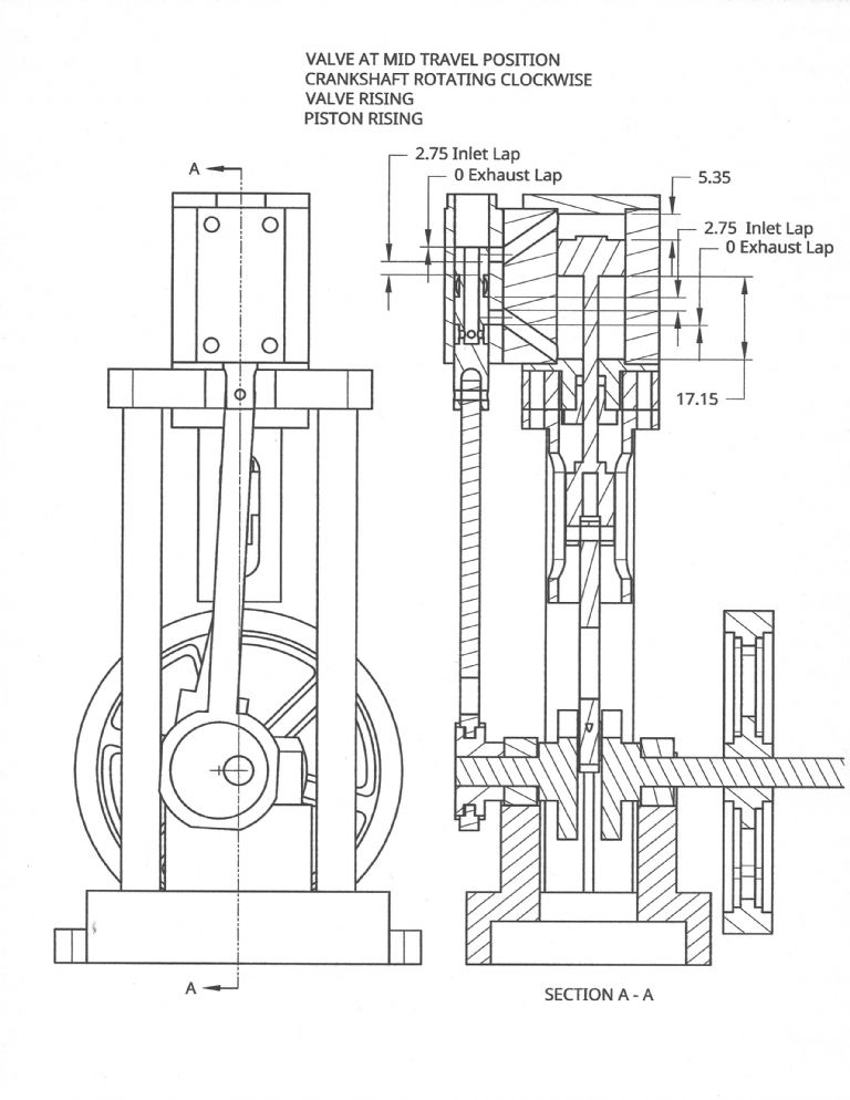
                                              The following drawing shows the valve I designed to try to get approximately 50% cutoff with the existing eccentric and valve linkage. The existing valve has a 0.4mm inlet lap and a 0.6mm exhaust lap. My revised valve has an inlet lap of 2.75mm and no exhaust lap. It wasn’t until I made a series of drawings to check the valve operation that I learned the importance of exhaust lap. Valve Mid Travel Position

                                              #394221
                                              Turbine Guy
                                              Participant
                                                @turbineguy

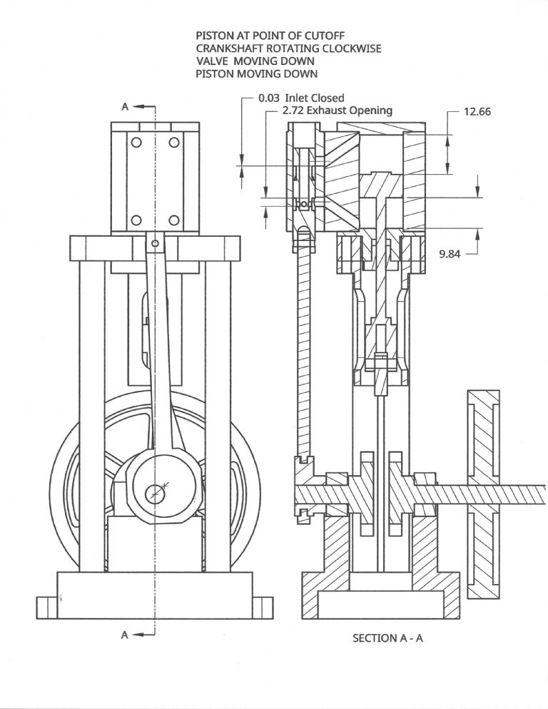
                                                The following drawing shows the distance from the cylinder cover to the piston when the inlet valve closed. The distance traveled minus the clearance distance divided by the stroke is the cutoff. The actual clearance is 2.25mm, so the cutoff is approximately 58%. Because of the time it takes to close the valve, the effective cutoff is probably close to the 50% I was trying to get.

                                                Valve Cutoff Position

                                                #394223
                                                Turbine Guy
                                                Participant
                                                  @turbineguy

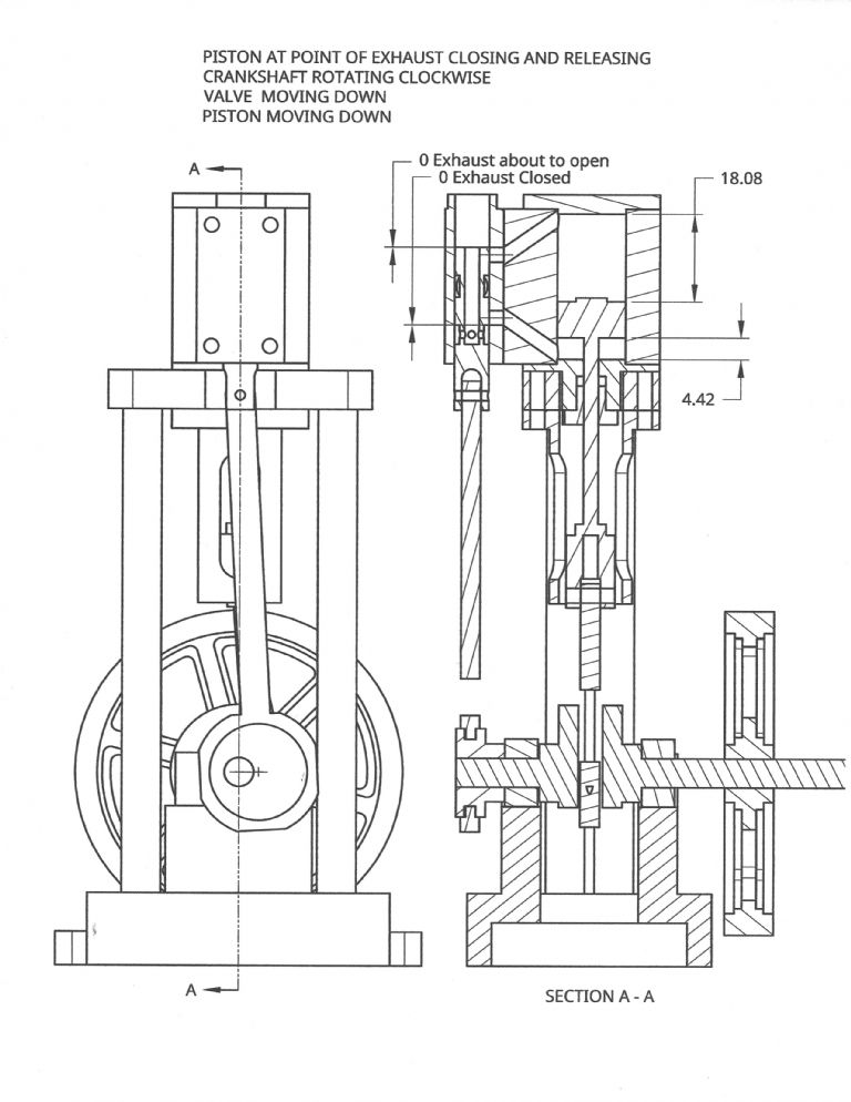
                                                  The following drawing shows the distances from the end plates when the exhaust closes on each side of the piston. The distance below the piston is used to calculate the volume of trapped steam or air that is compressed. I estimated the amount of power to compress the trapped air to be approximately 0.67 watts. The distance above the piston is used to see the point in the stroke the exhaust is released. The distance moved by the piston 18.08mm minus the clearance distance of 2.25mm and is approximately 15.83 mm. Since the stroke is 18mm, the air is released 2.17mm before the piston has moved the full stroke. I estimated the power lost due to the early release to be approximately.0.85 watts. In my original estimate of the power with the revised valve, I missed the early release. With this loss, the gain in power would be very little. The cure to this problem would be to add exhaust lap. The exhaust lap would almost eliminate the early release but increase the compression. If I could add the required exhaust lap, I would probably get the performance I first estimated. There isn’t enough room to add the required exhaust lap so I will have to look for a better way to improve the performance.

                                                  Exhaust closed and release points

                                                  Edited By Turbine Guy on 01/02/2019 18:37:39

                                                  #396000
                                                  Turbine Guy
                                                  Participant
                                                    @turbineguy

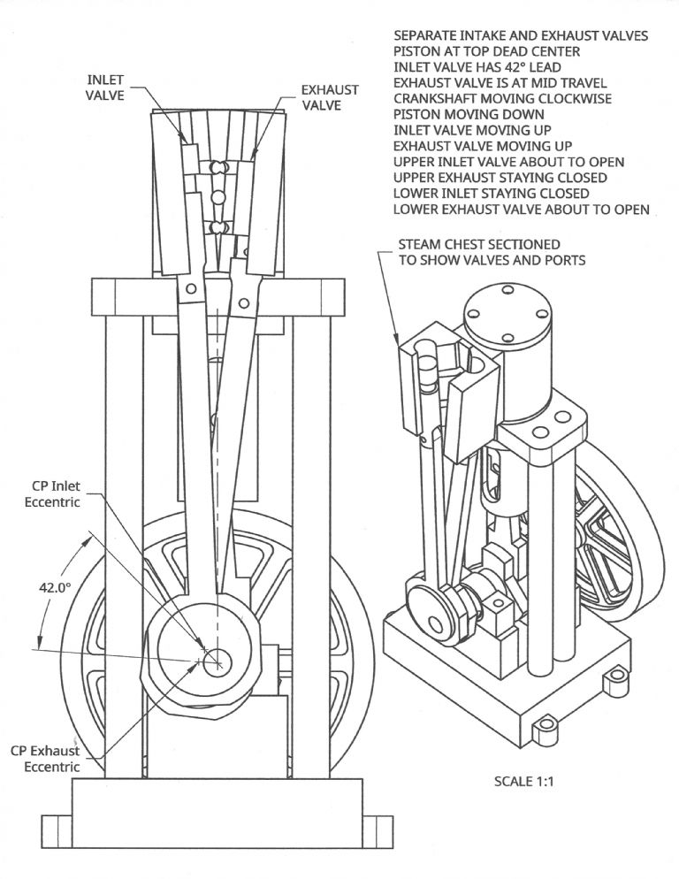
                                                    I decided I would have to make separate exhaust and inlet valves to substantially increase the efficiency. The link **LINK** confirmed the increase in efficiency with separate valves. This article also gave me enough information that I could check my formulas and methods of estimating performance with some actual test data. I used the 1.27 in. bore, 2.00 in. stroke, 15% clearance volume, 38% cutoff, early release distance of 0.30 in., exhaust closed distance of 0.44 in., inlet pressure of 38 psig, superheat of 81.2 C, and 502 rpm engine speed shown in fig. 6 for the conventional valve. With these inputs and using my equations I calculated an indicated power of 116 watts. The test result was 119 watts so my equations and methods appear to be valid. The following drawing shows a concept to add a second valve to my existing engine. Separate Valves TDCAdding the separate valves requires 1 each of the following new parts, a valve chest, inlet valve, exhaust valve, eccentric, and a valve connecting rod. To get maximum efficiency I would also add new top and bottom cylinder covers to the preceding new parts. These covers would extend further into the cylinder to reduce the piston clearance from 2.25mm to 1mm at each end of travel.

                                                    #396151
                                                    Turbine Guy
                                                    Participant
                                                      @turbineguy

                                                      With the preceding new parts, 14mm bore, 18mm stroke, air with an inlet pressure of 24 psig, a exhaust pressure of 0.0 psig, and a mass flow of 1.74 lbm/hr. the input power is approximately 17.5 watts. The average cutoff for each side of the piston is approximately 52%. The estimated output power is 7.52 watts. The estimated hydraulic efficiency is 66.9% and the estimated overall efficiency is 41.9%. Adding separate valves and reducing the clearance volume increases the power by approximately 2.8 watts, a 60% improvement, but requires 7 new parts.

                                                    Viewing 25 posts - 26 through 50 (of 125 total)
                                                    • Please log in to reply to this topic. Registering is free and easy using the links on the menu at the top of this page.

                                                    Advert

                                                    Latest Replies

                                                    Home Forums Stationary engines Topics

                                                    Viewing 25 topics - 1 through 25 (of 25 total)
                                                    Viewing 25 topics - 1 through 25 (of 25 total)

                                                    View full reply list.

                                                    Advert

                                                    Newsletter Sign-up