TECO 7300CV serial interface

Advert

TECO 7300CV serial interface

Home Forums Electronics in the Workshop TECO 7300CV serial interface

Viewing 23 posts - 1 through 23 (of 23 total)
  • Author
    Posts
  • #356387
    Robin
    Participant
      @robin

      I got a TECO inverter for my mill, never being one to make things easy for myself I opted for the RS232 cable rather than the speed control knob.

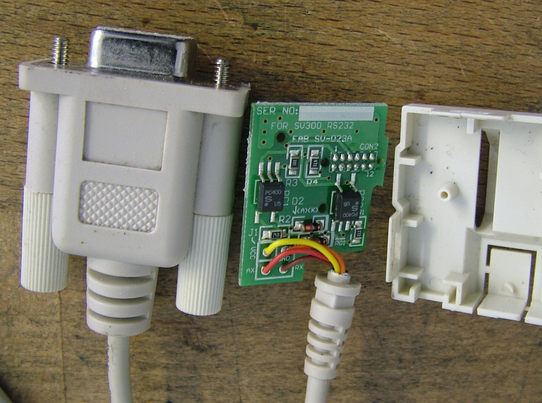
      I laid out a circuit board with an RS232 connector, IBM style, but the TECO manual was very squiffy on wiring detail so I took the adapter apart.

      I will be relaying my PCB to have a dual op-amp where the RS232 used to be because nothing else makes sense face 22

      I think this is the programming manual, curious because it only lists RS-485 and RS-422, plus it's at tecowestinghouse.com but Firefox won't go near it, it is somehow dodgy link

      Advert
      #31948
      Robin
      Participant
        @robin
        #356406
        David Jupp
        Participant
          @davidjupp51506

          That manual is for a different model – this is for the 7300CV **LINK** – very basic information for the RS232 interface on page 6-9

          This page seems to link to the software to 'talk to' the drive

          **LINK**

          #356423
          Robin
          Participant
            @robin

            At risk of teaching Granny how to suck eggs, this 7300 CV manual is the paper manual that comes with the inverter, I have that.

            If you buy the inverter with the RS232 interface cable you get one without the speed control knob on the front panel and absolutely no clue as to how to talk to it. I think they presume nobody would be stupid enough to buy it if they didn't have some third party software to drive it.

            If you moan at them they send you a weird program that tries to interface you with the inverter. Possibly talking to it as a PID because that is the language they assume you speak.

            I have this crazy idea that the inverter is the 7300 PA, the PA-C is a card inside that allows you to plug in various devices to control it and the PA-C communication manual is how to talk to the inverter at base level using the communication protocol of your choice.

            I could be wrong but I need the connection before I can say "Hello world" and see if a voice from the darkness answers back smiley

            #356427
            SillyOldDuffer
            Moderator
              @sillyoldduffer

              Fun and games that Robin may not want to bother with !

              VFDs are computer controlled. They are pre-programmed by the manufacturer to manage the basic generation of three-phase power and also allow the user to configure the unit to suit particular motors and control requirements.

              A typical configuration sets permanent details like the motor characteristics, how the unit should ramp power up and down normally, how it should manage an emergency stop, and what controls are connected. There are many configuration options, for most of them the defaults are fine.

              Most stand-alone VFDs come with a plugged in calculator-like device that lets you alter the configuration. For most purposes this method is more than adequate; you tap in the motor rating, and identify the ON/OFF, START, STOP, EMERGENCY STOP and interlock connections etc. Usually the speed control is allocated to a potentiometer. Once the VFD is set-up, there's no need to change the configuration. Just as well because struggling to understand the manual may have permanently damaged your sense of humour! (New machines pre-fitted with a VFD are configured by the seller, you don't have to touch the configuration at all.)

              The calculator interface isn't a good way to manage many VFDs in a large installation, or if you're making ready-to-go VFD controlled equipment. Then it's more efficient to sit in a comfy office in front of a laptop, PDA or smart phone. When a new VFD is installed or configuration changes are needed, you arrive with a laptop and download the configuration in a flash. Also removing the calculator stops unauthorised persons from messing with settings. Few hobbyists I think would need RS232 for this purpose.

              The second reason RS232 is useful is to dynamically monitor and/or remote control a VFD. For example you might want a finer level of control over an overheating motor, to sound alarms, or even email maintenance when faults are detected. Remote control of the VFD makes it possible to eliminate the human operator. Again, I feel most of us are unlikely to need remote control. (You may know different. Hobbyists have wide interests!)

              Robin's RS232 circuit looks like a simple opto-isolator. It makes sure there's no physical connection between nasty dirty power and an expensive computer or the operator. Unwise to replace it.

              To set up RS232:

              • Both ends of the link must be configured to match Baud Rate, Stop Bits and Parity setting.
              • Might also have to set matching flow-control, either hardware or software.

              Once the link is active, the computer sends a well-defined message to the VFD and the VFD replies with a well-defined answer. Teco 7300 Protocol Details described here. The PC has to be programmed to ask the right questions and to handle the answers.

              As writing software to implement a protocol is quite involved, it's very likely that Teco (or someone else) has developed a software package to do it. Sometimes they're freely available off the internet, sometimes they're Price on Application.

              I'd put the RS232 in a box and order a speed control knob!

              Dave

              #356428
              Mike Poole
              Participant
                @mikepoole82104

                I think you will need to either get the Teco software to communicate with the drive or buy the keypad with pot to set up the drive. Many more sophisticated drives can be networked to a PLC or other host and use a variety of industrial control protocols like interbus, Modbus, profinet, and many more. The comms standard can be very varied also, Profinet, RS232, RS422,RS485, controlnet, DH+ and many more. Apart from a convenient way to program a drive from a software package which can sometimes access parameters not available on the keypad then for a standalone drive I would stick with the keypad version. It looks as if you just need to get a keypad and you will soon be up and running.

                Mike

                #356434
                Robin
                Participant
                  @robin

                  Modbus would appear to be a daisy chain configuration to hang multiple inverters from the one host. On the face it appears the same as the PA-C interface but is still a most excellent find that I will go through as soon as time allows. Well done Duffer laugh

                  The cable proclaims to be RS232 but isn't. There is no need for me to try and come up with plus minus 12 volts when everything above 5V or below zero will be ignored anyway.

                  The TECO software is written for a PC. I want to drive this from something completely different.

                  #356437
                  SillyOldDuffer
                  Moderator
                    @sillyoldduffer

                    I missed David's link to the software earlier, but it looks right.

                    'hello world' shouldn't be difficult. The unhelpful manual doesn't say what the default RS232 settings are, but it does say speed can only be 4800, 9600, 19200 or 38400 baud.

                    With a serial terminal like putty or hyperterminal, find the com port and try 9600 baud, 1 stop bit, No Parity, 8 bit data, no flow control, which is a common default.

                    Then type in:

                    :01865128<Enter>

                    With luck the VFD will reply with whatever error code is showing on the LED display.

                    This seems to be the only example in the manual where they've pre-calculated the Cyclic Redundancy Check values used to confirm messages haven't been corrupted en-route. Otherwise you have to work them out yourself for each command. How to calculate CRC is explained starting on Page 3 of the Protocol Manual.

                    For testing you might simply try sending the VFD a line of garbage. When the CRC is wrong or the command not understood, it should reply with an error code and display "Err6", proving that the link is working or nearly working, (connection OK but wrong speed/parity etc are garbling the message.)

                    Dave

                    #356440
                    SillyOldDuffer
                    Moderator
                      @sillyoldduffer

                      Posted by Robin on 04/06/2018 11:07:27:

                      The TECO software is written for a PC. I want to drive this from something completely different.

                      Ho, that's clever, and there's me assuming you had probably bought the wrong option. Apologies!

                      Struck me scanning the protocol that driving a VFD might make an interesting microcontroller project. An Arduino could handle it easily, as could all the others.

                      Dave

                      #356441
                      Robin
                      Participant
                        @robin

                        I could try, but what about the RTS pin where it expects 5 Volts to drive the RX pin?

                        If I had a 1488 line driver with access to a +-12V PC PSU then I expect it would work. However I only have 100mA of 5V being squeaked up and down by a USB to serial adapter.

                        I think I need to lay out the PCB so I can hardwire RTS to a hard 6 Volt rail laugh

                        #356449
                        Neil Wyatt
                        Moderator
                          @neilwyatt

                          With RS232 always start by assuming the PC is using the wrong com port and baud rate.

                          #356452
                          Robin
                          Participant
                            @robin

                            The Baud rate and stuff is either switches or front panel selection, can't remember.

                            I want on/off, not reverse and frequency determined by the G code. Those accidental reversals are seriously unfriendly.

                            For lights out operation I want stall/over torque detection so I can 'pause cut' and 'call for help'.

                            If the torque is readable then it might be possible to detect a tool break or know if the drive belt is on the wrong pulley pair.

                            Such fun smiley

                            #356461
                            SillyOldDuffer
                            Moderator
                              @sillyoldduffer
                              Posted by Robin on 04/06/2018 11:49:42:

                              I could try, but what about the RTS pin where it expects 5 Volts to drive the RX pin?

                              If I had a 1488 line driver with access to a +-12V PC PSU then I expect it would work. However I only have 100mA of 5V being squeaked up and down by a USB to serial adapter.

                              I think I need to lay out the PCB so I can hardwire RTS to a hard 6 Volt rail laugh

                              Try it and see. RS232 implementations have always taken a slack attitude to the standards and most modern kit (I think) will work with 5V logic levels. Quite likely to ignore RTS/CTS & Co as well.

                              When RS232 first appeared it worried about driving 1950's electro-mechanical devices like tele-typewriters over noisy wires. Electronics didn't take long to remove the need for lots of volts and milliamps, and clean up the signals.

                              The standard covers 20 or so control wires, most of which are rarely used. Over time the interface has tended to simplify by ignoring most of them. Modern chip sets may be brainy enough to work out what's needed without using any control lines at all.

                              Wiring up and getting the volts right can still be problematic because implementations vary but there's a good chance the electronics will sort it out, perhaps firing up with only 5v logic RX, TX and GND. Older gear is much more likely to be fussy than new stuff.

                              Tecos documentation suggests their RS232 is simple, ie straightforward. Assume it's easy unless it doesn't work!

                              Dave

                              #356478
                              Robin
                              Participant
                                @robin

                                If Teco wanted simple RS232 why didn't they stick in a MAX232 chip requiring no external power supply?

                                Do we presume 'elf'n'safety? face 22 smiley

                                #356481
                                Mike Poole
                                Participant
                                  @mikepoole82104

                                  A useful frig on RS232 is to link pin 4-6 and 7-8 to satisfy the handshake lines. As these are not through wired on your cable they may already be wired in the moulded end. The other trip up point is the Tx and Rx are often crossed despite what the standard says. A breakout box is most useful for troubleshooting RS232.

                                  Mike

                                  #356484
                                  SillyOldDuffer
                                  Moderator
                                    @sillyoldduffer
                                    Posted by Robin on 04/06/2018 14:48:39:

                                    If Teco wanted simple RS232 why didn't they stick in a MAX232 chip requiring no external power supply?

                                    Do we presume 'elf'n'safety? face 22 smiley

                                    Perhaps they did – I don't see anything asking for an external power supply? Are you trying to make the whole option unit, rather than just use the RS232 port that it provides?

                                    The DB9 connector on the option plug-in looks simple enough and there's a note saying CTS is 5V.

                                    teco.jpg

                                    Dave

                                    #356501
                                    Robin
                                    Participant
                                      @robin

                                      Pin 7 on a db9 would be the output pin RTS. To make it high you have to set RTS=0 in the UART. The output then drives through what I take to be a 1n4148 glass diode before powering a PC400 isolator.

                                      The TX line back to the inverter looks even less friendly. When they want to light up the opto-isolater on RX they drive through a 470R, when I want to light the other side I have to drive through a 2k43. I can see that coming out dont know

                                      #356512
                                      Neil Wyatt
                                      Moderator
                                        @neilwyatt

                                        The unit clearly ignores CTS/RTS as it only has RXD/TXD wired up.

                                        If the PC adaptor uses an FTDI chip it should generate enough on CTS to work the optos.

                                        Keeping the optos seems a good idea to me. Potential(ho ho) to get quite a voltage from inverter to computer if there's a ground loop.

                                        However baud rate is set at the inverter, the PC still needs to be set to match, experience shows that trial and error takes a long time…

                                        #356531
                                        Robin
                                        Participant
                                          @robin

                                          Latest plan…

                                          I drive TX with an op-amp wired as an inverter, an easy way to get 5V to light the TX LED.

                                          I handle RX with a comparator wired the same way. The processor pins are 5V tolerant but why take a chance?

                                          I hardwire pin 7 to power.

                                          Simples smiley

                                          #356536
                                          Anonymous

                                            If Rx and/or Tx aren't swinging plus and minus around 0V it isn't RS232.

                                            Unless you're going to do something clever with virtual earths for the opamp it isn't going to work very well as an inverter on a single supply, unless I've missed something somewhere.

                                            Andrew

                                            #356546
                                            Robin
                                            Participant
                                              @robin

                                              RS232 is a combination of V24 and V28.

                                              IBM did away with V24 and the Chinese have now done away with V28.

                                              Perhaps RS232 only exists as a microprocessor die labelled UART nerd

                                              #356548
                                              SillyOldDuffer
                                              Moderator
                                                @sillyoldduffer

                                                The thread illustrates my earlier comment 'RS232 implementations have always taken a slack attitude to the standards.' Might add the standards are open to interpretation, have changed several times and are more than a bit confusing!

                                                Swinging 12v +/- around ground is a good way of getting a digital signal along a long dodgy cable to a receiver that's not very smart. In 1960, ±12V was considered daring – teleprinters needed ±70V. Progress occurs, and a modern implementation will recognise less sharply defined logic levels: provided it can tell the difference between '0' and '1', that's good enough. Most 'RS232' will work with 0v and 5v.

                                                RS232 has a DCE end and a DTE end. Between the two, wires are crossed over, for example Transmit (TX) at one end is connected to Receive (RX) at the other. CTS and RTS operate as a crossed pair allowing both ends to tell the other that the link is ready to exchange signals. However in this case, RTS isn't used to confirm readiness, rather it's used as a source of volts to power the opto-isolator (which has the same effect). The volts could be provided by telling a UART to do full standard RTS as Robin suggests, or by sticking a battery on it! As most USB/Serial converters take RTS high anyway, CTS should have volts on it. Try it and see.

                                                I don't think there's any need to worry about the size of the resistors or fiddle with op amps. The amount of power needed to work an opto-isolator is miniscule – the speck of light only travels about a millimetre.

                                                Dave

                                                Edited By SillyOldDuffer on 04/06/2018 22:03:24

                                                #356549
                                                Robin
                                                Participant
                                                  @robin

                                                  Both lines still need to be inverted

                                                Viewing 23 posts - 1 through 23 (of 23 total)
                                                • Please log in to reply to this topic. Registering is free and easy using the links on the menu at the top of this page.

                                                Advert

                                                Latest Replies

                                                Viewing 25 topics - 1 through 25 (of 25 total)
                                                Viewing 25 topics - 1 through 25 (of 25 total)

                                                View full reply list.

                                                Advert

                                                Newsletter Sign-up