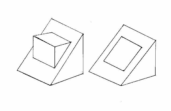
Well, since unreferenced lines are allowed on drawings (although this is like steam trains whistling in stations – not wrong; we just don’t do it), here are two solutions sketched. The first is Geoff’s one – probably the neatest way. But the second isn’t absolutely wrong either. You can work out what the side views of each would be very easily, I think:
I prefer Geoff’s. Sorry for the awful sketch, but you get the idea… and you don’t want me to draw a cube, now, do you? Not if it looks that bad anyway!
Thanks for making me read Geoff’s explanation a second time (and understanding it this time.) I think my rigid preconception that it had to be a cube even hindered my understanding of Geoff’s explanation on the first reading. Geoff, I do not think there is anything wrong with your description of the object – it describes it perfectly.
Ok, I’m going to stick my nose in, and expect to get well and truly slated!
Drawings. Should be clear and easy to understand. Is it absolutetly necessary for them to adhere to BS 308 or whatever? No, it is not. This is a hobby, for heavens sake, and as long as the hobbyist can make his widget from his drawing than that should be enough.
Now, ok, I am going to get slated for that. But I am going to say something else which may just throw some light on why I say it. I am an ex-BT technician. I am, or was, used to cables with literally hundred’s of wires in them, and ok there was a code to follow. But the same colour could appear many, many times. I was also used to interconnection frames where there were hundreds, even thousands of interconnections all using the same two colours. (Or 3 or 5 depending). How did we cope? Easy-peasy, we had various tricks up our sleeves. Now, I look at the recent hoo-hah over Part P and household wiring. It is so simple it is almost laughable. And there are only three colours, or five if you’ve got mixed schemes. So does it really matter which colour is used for what purpose? Does it heck! It’s an aid to wire identification. Any electrician worth his salt should know what is going on and be able to sort it out accordingly without relying on colour coding to mean this or that.
And so it is with drawings. If, as an amateur you are going to make something, then you should have an idea as to what it is. Does it really matter if it is to BS308 or HA 456 or USD90. Does it heck – as long as you know what is happening.
As it happens, I have both Tubal Cain’s book, and Derek Brown’s book. I do not follow slavishly either person’s ideas because they do not fit my own scheme of things, yet I would say that the drawings I have produced are understandable. For example, I do not use multi-weight lines. Why? Because it starts to get messy on the VDU. I use a colour scheme and layers to my own design. It works for me, and any drawings for publication are simply converted to black on white. I do not use 1st angle – it does not make any sort of sense to me, yet 3rd angle makes absolute sense so that is what I use.
Finally, may I point out that those people who say that it MUST be done this way or not at all are simply showing that they are unable to see other options.
Right, I will now stand by for my expected telling off.
I think David is possibly very much in tune with the future of engineering in the home workshop environment. The younger fraternity have good computer skills and have been using 3D sketching to CAD sotware and have pushed general engineering forward into new fields. Many of the readership will have CNC machines and be conversant with designing parts to be made on these.
Your offer of a series on technical drawing might have had more appeal if it was to address the problem of bridging the world of third angle projection and 3D CAD / CNC. The new engineers do not think in terms of sections and dotted lines and I suspect have no desire to make the objects described on paper with third angle views. However as CNC and 3D CAD penetrate even deeper into the home workshops there is a need to bridge that divide. A simple example is the conversion of a simple dimensioning of a fixing flange with holes on a pitch circle into co-ordinate parlance with out getting into some ridiculously tight tolerances.
Can I look forward Terry to such an article being offered to David as this would probably have much of the same material but be of wider interest. The more articles that are offered the better the magazine – Kind regards – Pat
I think your second solution is feasible, but I think you missed out a line? as I interpret it that is a square hole through the cube, or is it an engraved rectangle on the angled face?
No, they were ambiguous lines on a drawing – object incompletely specified. And that’s exactly the point – ambiguity. It had lines on it that you had to consider carefully before you came to some possibly ambiguous conclusions. In the real world, hopefully people don’t do that to you – but they can certainly come pretty close, as a few contributors have indicated.
But it certainly adds some credence to Terryd’s idea that an article looking into the ways that drawings can be interpreted is necessary, I think. Even though there were some obvious answers (like the cube, although that also left you with some questions about what those other lines really were), nobody until Geoff came up with anything like the (correct? standard?) answer, did they? Was this just because nobody wanted to look stupid? Or was there some real ambiguity in the ways that people were thinking about this? There are a few hints in this thread that there were – and kudos to those that have actually admitted to it.
I’ll freely admit that I’ve been stretching the normal principles of drawing with the ‘lines’ ambiguity. The principle taught is that a single line should represent either an edge, or the change in direction of a surface, and to do this you need at least two views to express this clearly – and as we have seen, sometimes more. Another good example is a ball bearing – you simply can’t draw that in a single view at all. With just one view, it could just as easily be a sphere. It’s also been suggested in print in at least one drafting book that it could be a cylinder, but I’d say that if it was, it would have to be an infinitely thin one. The same book also says, in a quite breathtaking understatement, that ‘a certain amount of imagination is therefore required when interpreting engineering drawings’. No, really?
The new engineers do not think in terms of sections and dotted lines and I suspect have no desire to make the objects described on paper with third angle views.
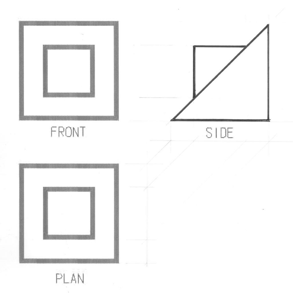
Hi, now that the cat has been let out of the bag for Sam’s test, I’ve drawn it for those who still can’t see it.
I must admit I did not get it without the explination that Geoff’s gave, although I had the idea that it was half of a sliced cube for the mnin part, it was the little one that stumped me. I should have attempted to draw it in the first place.
You may be able to see the projection lines which show how it was achieved.
As a matter of interest for perhaps nobody, BS308 was superceded in , I think, the year 2000 by BS8888 which encapsulated the old BS308 together with a lot of the latest ISO standards.
This included the dreaded “,” comma instead of the “.” decimal point.
Any amateur (or professional ) model maker / machinist/engineer will at some stage ,have to read and understand 2D drawings . After all it is one of the most important basic international communication channels between engineers. If a drg. is made to recognisable standards then it can be read by any engineer in any country ( with some translational and eng. standards info as required) . It doesn’t matter if it’s in english 1st angle or ISO 3rd angle as long as it is correctly identified. Parts can still be made from drgs 100s’ of years old.Most drgs I’ve encounted could be read as long as they are clear and to a recognisable format and is made by someone with a little common sense and have been checked by a professional.
To fail to try and understand drgs will make life quite difficult in this engineering world of ours for anyone in this hobby.
There many books on the subject from the most basic to the most advanced. Perhaps a list of these books could be compiled for the benefit of forum members ?
It’s a great shame that technical colleges do not run engineering drawing classes ( & CAD courses) that are affordable.Some of the current CAD course fees seem excessive.I would have thought basic classes in eng. drg. & CAD would have rated more highly than some of the “media” studies that seem to offered by a lot of the current colleges, and these engineering courses should be Government subsidised as part of the support to industry. It could be argued that free engineering courses/ classes would benefit the country . Of course some colleges would have to spend money on new equipment to replace the perfectly servicable equipment that they sold at a fraction of their true worth when they decided they were no longer needed !
I have noticed some poor practice in current ME/MEW drgs where shaft / hole diameters are dimensioned from end views using arrow headed leaders to the circ feature. Where there are a number of shaft stepped diameters and maybe stepped holes it is quite difficult to discern which diameter the dimension refers to.These dimensions may be clear to the contributor when viewed on a 24 inch monitor but are not clear when printed in the magazine. It’s quite acceptable to place a dimension across the drg to the relevant diameter rather than extend the dimension outside the item outline in order to make the dimension more clear.
My pet hate on some 3 CAD programmes is that sometimes it’s difficult to change some of the 2D semi-automatic drg defaults to make some aspects more clearly defined. There are ways around this but it involves extra work !
The importance of good drgs & CAD models becomes very clear when drgs / files can be sent across the internet and can be immediately viewed & understood & used by the recipient.
It has been mentioned before on this forum that a perfectly good free 2D drawing program can be down loaded from the Solidid Ege website
With the cat out of the bag, Nick has shown one of the solutions and has clearly used 3rd angle projection.
Or has he?
Don’t take this personally Nick, because (I hope) I’m trying to bring attention to an important part of Terry’s original idea.
If it were (all) 3rd angle dangle, sorry projection, shouldn’t the small square of my original PLAN view be dotted? And where should the PLAN view be positioned to avoid this? In the words of `Top Gear’ James May “Oh cock!”
While, from a young age, I learned to draw in 1st angle (as a Pomme – English projection comes naturally), I have become `tolerant’ to 3rd angle projection, a method better suited to drawing very long objects such as aircraft and ships.
However, I still maintain (and have taught for many years) that 1st angle is by far the better system for moulds of the injection type. In the plastics industry (especially this country), countless drawings are constructed in 3rd angle, an Australian industry `standard’. Sadly, the views and sections end up in all sorts of weird positions, contradicting the basic rules of 3rd angle, and showing little to no resemblance of how the mould is positioned in the moulding machine. The primary desire appears to be to use up as much space on one drawing, with part of the mould sitting sideways on the bench.
Then along came CAD.
This was the door which opened us up to the wonders of 3D solid modelling but, I believe, caught a lot on the hop. To keep pace with a changing world, they had to learn CAD, and with most commercial software, months of training was often required (and still does).
Personally, other than the cost, I found 3D CAD a delight, and only look(ed) upon 2D as a means of initial construction or when conveying information when my client requested dimensioned (paper) drawings via the plotter.
Perhaps we should wait a little longer for someone to show us other alternative solutions to what has become known here as Sam’s test!?
Best regards to all who sail in her,
Sam
By the way, is a nurd, (nerd, nurd), Imperial or Metric?
Posted by The Merry Miller on 20/04/2011 22:16:56:
As a matter of interest for perhaps nobody, BS308 was superceded in , I think, the year 2000 by BS8888 which encapsulated the old BS308 together with a lot of the latest ISO standards.
This included the dreaded “,” comma instead of the “.” decimal point.
Never did like the comma!
Hi Merry,
I did actually point that out, but as I understand it at the moment, the standard you refer to is an interim transition to ISO standards which is to date in it’s 4th incarnation in preparation to the adoption of full ISO at some point in the future.
As many have pointed out in this thread, as modellers we are not tied to industrial standards, but many of the orthographic drawings that we will come across in kits, books and magazines from the past will have been drawn pre 2000 and will have at least a passing acknowledgement to BS 308 (how many still like to make E T Westbury’s models or G H Thomas’ tools) .
My very good friend Eric Whittle, (recently departed), of the famous 3.5cc Vee 8 aero engine which won many awards, used BS 308 standards in his illustrations for his constructional articles, and many still would like to replicate that model so will need to have an understand the nuances of that language.
In 30 years time I may be asked to write a commentary on BS 8888 and ISO standards, and as long as these mortal coils allow, I would be prepared to write about them.
To paraphrase Bob Dylan, “We’re Getting There, But We’re Not There Yet”
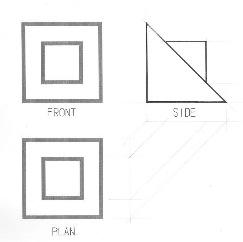
Hi Sam, no offense taken, but as you say a clear case of understanding drawings. Quite wrongly I based my projection on the two sketches that Steve Granett posted and lost sight of the projection angle. I’m not blaming Steve by the way, but just goes to show we can all go back to school now and then.
So for all those who are now even more confused here it is again in Ist angle projection. (I hope!)
As far as “the way things are going” is concerned, I think 3D modelling is a great thing for “our” sort of stuff. The reason is that the process is reasonably analogous to making a part in the workshop, assuming of course that you could extrude sections as well as machine bits away. You draw a circle, extrude it out to some depth and you have a cheese shaped thing. Now you draw another smaller circle on one of the faces and extrude that out a bit longer. You tell it to put a thread on the end of the longer skinny bit, cut a slot in the cheese shaped end, and suddenly you are looking at a cheesehead screw. Having made the model, you can then tell the program to make any of the standard views, and it will do them for you in either first or third angle. It will also knock out a nice set of isometric views for you too, which I find are really useful to help with sorting out those ambiguities.
Now, anyone who has tried will tell you that the automatic views are not exactly publication ready as they come….the programme will put in dimensions, but not necessarily the ones that you should put in. So a bit of knowledge about how you should dimension it is useful, since it is quite easy to take out the silly ones and put in sensible ones. For instance, all measured from a datum at one end, rather than a whole lot of individual measurements that someone has to add up to get the total. Depending how you have made shapes the programme may also decide to put in radii rather than diameters. A bit of nous about which view are needed to make sense of the part and which can be eliminated also comes in handy. I only have the poor mans version of the least expensive of the packages around, so mine does not have all the fancy features, like automaticaly doing sections for you. (I can do them, manually with a bit more effort.) So knowledge of when a section would be a good idea is also useful.
So OK, I am talking from the point of view of making drawings, while Terry was talking about interpretation, or reading if you like, but you learn to read before you learn to write, and the one will help with the other. I don’t think anyone is sitting around waiting to say “but that drawing does not conform to BS308”. The idea is to communicate, for which it helps if people are talking some approximation to the same language.
I wonder if a way to make this more interesting to the general than some seem to fear would be to actual combine it with a short construction series for something not too complex? As well as the information about the part and how to make it, include the information about why the part is shown as it is in the drawing.
Anyway, certainly some people don’t find the topic too boring, we are up to seven pages of discussion already.
You can work out what the side views of each would be very easily, I think:
… or not, judging by what happened subsequently! And I’m not casting judgements on anybody – after all, there but for the grace of God go I… But that’s not why I didn’t do proper views though – I just sketched these out with no particular care about an accurate view at all, as I was only trying to put Geoff’s (possibly more elegant than he thinks) words into some sort of a picture. This was because I’m moderately convinced that for some people, words alone just don’t do it. But it really does go to illustrate just how much care you have to take with even relatively simple things sometimes, doesn’t it? And possibly reinforces Terry’s original view on this too.
To post or not to post, that is the question. But then somebody on this thread wrote that many have viewed but few had contributed a post, so I guess that’s the answer to the question.
I learnt Technical Drawing/Engineering Drawing at my Secondary Modern school and then at the College of Technology that I went to. I remember my school teacher’s instructions on line weights to this day “If I can see your construction lines from here then they’re too heavy”. At college BS308 was quoted several times a lesson. Of all the subjects that I studied engineering drawing was the only one I didn’t have to revise for, I knew I would be able to get a good pass or a credit without revision. Possibly had I revised I could have got a distinction, but the name of the game was to pass. Not revising ED gave more time for revising other subjects. Which was all of them. But I digress.
I learnt ED 45 to 50 years ago. Since then I have used ED’s often, not to make anything until now but to understand how things came apart, and went back together, or what the finished project would look like. Only in the last 15 years have I had to do drawings again, on paper and now on CAD.
But the little grey cells grow tired and forget what they have been taught and a series of articles in MEW would be both interesting and a useful revision and undoubtably I would learn new things as well as relearn old. So that would be a really Good Thing.
I regard Engineering Drawings in the workshop as an essential tool, as essential as the kit required to mark out the job, the devices to hold the job in the lathe or mill, the cutting tools required as well as all the hand tools needed and the skills to use them all. You MUST understand what you are trying to make before you can set about making it, and you can only do that by the ability to READ and UNDERSTAND the drawing. So for me, a series of articles is every bit as interesting and informative as one on making tool grinding jig or an angle plate for example.
So good on you Terry for suggesting this and offering to write the articles, and shame on you David – and I am normally with you, on most things – for dismissing it so swiftly initially, although I do know you will now reconsider publishing said articles; I look forward to reading them!
ChrisH
PS. Terry, whereabouts in France do you go, presumably in Brittany? We live about 20 minutes from Carhaix and know the music festival well – we can sometimes even hear it from our place there!
Graham, I didn’t think you were doubting my ability, and I wouldn’t mind if you did. I was just trying to point out some of the pitfalls that might catch the unwary. To get back to drawing, the main thing is to convey information, and there are a few basics that need to be stuck to, center lines on cyl. objects, clear labelling of views, etc. The most important, is proper dimensioning from a datum. I could go on, and on, but I won’t. Drawing for amateur use need not be to professional standards ( ie. 308) and may be better if not.
Ah, postings are wanted, so here you get it. Sorry if this one sometimes sounds aggressive, That’s not what I want to express. Blame my limited knowledge of English please
My opinion, after following this discussion: does it really make sense to publish a (long?) series of articles describing the BSxxx standard? Considering that:
– ME authors (mostly, it seems) do not use it
– there is a big rest of the world who does not use it either.
I can finally understand David C’s position better. The long series about that 3D-CAD (which in reality wasn’t one, and used a outdated version to boot) was enough.
I don’t care much if something is drawn in first angle or third or whatever, if I can find the necessary informations to produce the part (and if the angle number is given somewhere if it is not absolutely clear).
Yes, I also saw the examples in the XYZ magazine, demonstrating that even a benevolent attempt at correcting something can result in a failure.
The professional drawings I get here are in first angle!
I have skim read through most of this post and I must admit, to being very dismayed at the indifference towards correct engineering drawing standards.
1st angle, 3rd angle or isometric drawings were developed so that engineers could understand how a part was to be produced. It matters not which discipline you were trained in, the principles are the same. I was fortunate during my school and apprenticeship years to have studied most methods of representation. I would suspect that the majority of the 40+ generation of mechanical engineers would have had a similar experience.
That said, there will be a great number of people coming into this hobby with little experience of reading engineering drawings.
Even if it is a generalised article, I think it would be beneficial to all to have an article giving the basic principles of reading and understanding engineering drawings.
If ME and MEW are to continue, I would highly recommend employing a profesional draughtstman to reproduce designs to a common standard.
We all aspire to be engineers so why do we not adhere to common engineering standards.