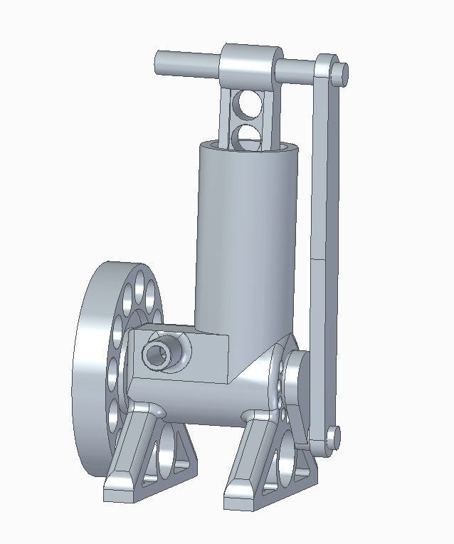
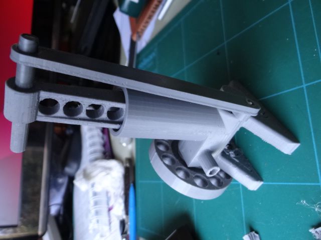
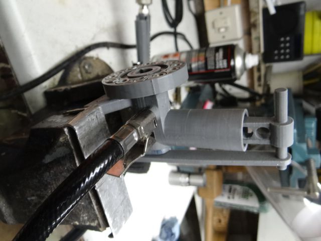
Thanks to the forum I had an urgent rethink this morning and designed a second, simpler engine. Despite many lessons learned, the Mark 1 engine has a lot of moving parts, hence friction, and will take about 24 hours to print, with no guarantee of success.
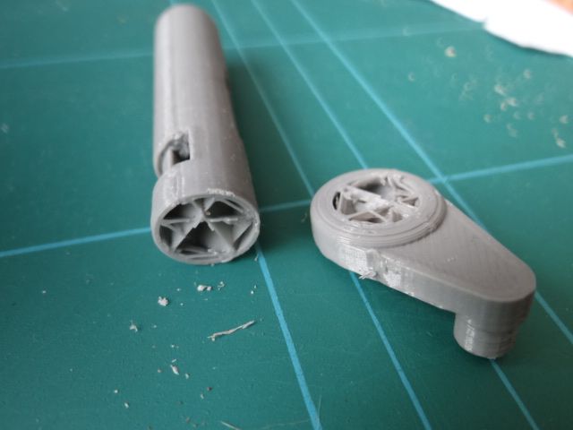
The second engine doesn't solve everything, but the rotary valve is incorporated in the main shaft and there's only one crank. Fewer joints to leak, only one fixing (holding the flywheel on), timing easier to set up, less plastic filament, and it will 'only' take 9 hours to print. Most important, I think it has a reasonable chance of running.

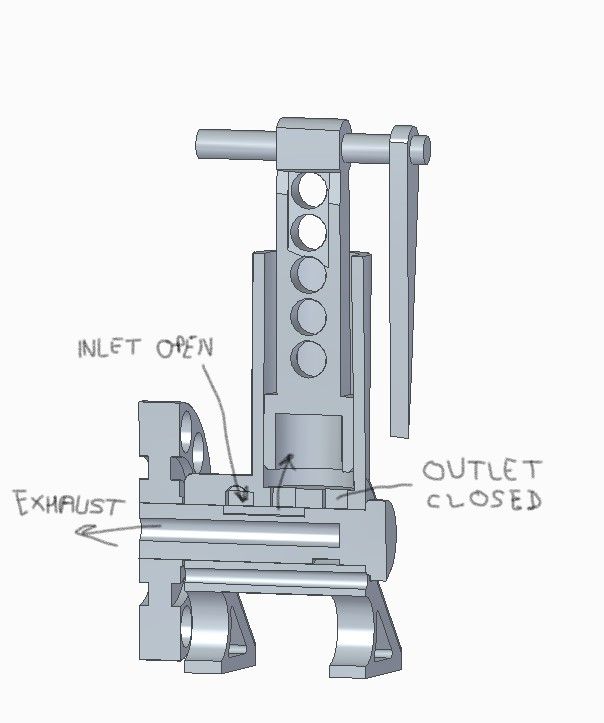
Air enters at the side and is fed to the cylinder via a slot cut in the rotary valve. It pushes the piston up to TDC at which point a groove cut part way round the rotary valve allows air to escape through a hole in the centre of the shaft, exiting at the flywheel. Section shows the slot connecting air to the cylinder while the outlet slot is closed.

Thinking about valve timings revealed another huge gap in in my engineering understanding, so I guessed! The exhaust gap is set to nearly 180 degrees, which is probably fair enough, but the input is open for 38 degrees. That seems like a lot, probably allowing more energy in than is needed to spin the engine. Might blow the piston clean out of the cylinder in which case I shall claim to invented an air-gun…
Anyone know what valve timings are suitable for an air engine of this type? I guess they depend on the required power output, which is unquantified, the friction to be overcome, which is unknown, and the amount of energy in compressed air at operating pressure.
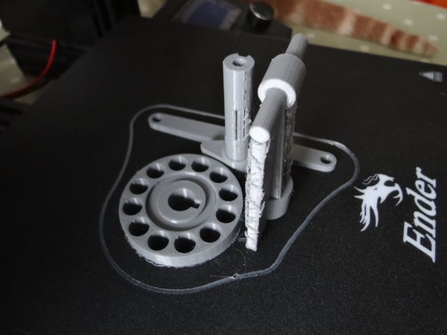
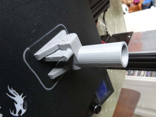
Watch this space, I'm about to start printing. We could run a lottery on the results:
- After mild fettling, engine runs first time
- After lots of fettling, engine breaks at the first puff
- Engine can't run because of basic design errors
- Engine can't turn because the piston stanchion and con-rod bend rather spin the crank
- Engine quickly seizes due to plastic on plastic galling
Only two cheats intended: although all parts will be 3D printed in PLA, the outer ring of flywheel holes will be loaded with plasticine and PTFE lube will be sprayed inside.
Dave
lee webster.


