Target for This Month: A 3D Printed Engine

Advert

Target for This Month: A 3D Printed Engine

Home Forums 3D Printers and 3D Printing Target for This Month: A 3D Printed Engine

Viewing 25 posts - 1 through 25 (of 40 total)
  • Author
    Posts
  • #601150
    SillyOldDuffer
    Moderator
      @sillyoldduffer

      Been busy developing my SolidEdge CAD skills by tackling various parts and assemblies. After replicating Jason's current engine in cyberspace, I've left him to build a real one. Don't want to get into a race because I reckon he shapes metal about twenty times faster than me!

      Thought I try something a bit different: with forum help can I design an engine that can be 3D printed and run on compressed air. There are interesting advantages and disadvantages.

      Advantages:

      • Plastic can be printed in almost any shape with internal cavities and passages that cannot be made with a lathe, mill or even casting. (3D printing is like casting on steroids!) It makes previously impossible constructions possible.
      • All the skill is in the CAD design; the parts are made by machine.

      Disadvantages:

      • Accuracy is limited compared with metal bashing; about 0.1mm on my hobby printer, and that's optimistic!
      • Finish tends to be poor, with ridges and blobs.
      • Limited to low temperatures – less than 100C.
      • Plastic's not very strong: the design might have to pay much more attention to stresses and strains than an equivalent metal engine. There's a strong incentive to reduce cost and print time by leaving holes in a thin structure wherever possible
      • It's at the limit of my understanding

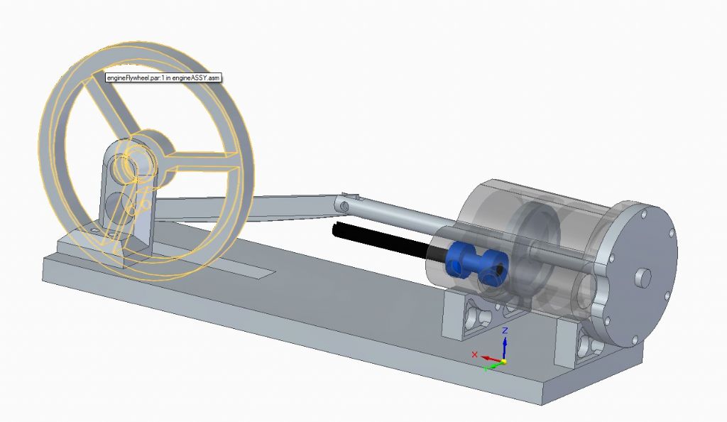
      First attempt was this double acting horizontal mill engine, very much based on metal models such as the PottyMill.

      3dhorizontal.jpg

      Main interest is in the design of the piston, which is coned for strength and supported at both ends so it can float to reduce friction, and eliminate the need for a cross-head, maybe. The cylinder is generously honeycombed with passages to open up airflow, as is the valve. The valve is oversized compared with steam because there's less energy in compressed air at the same pressure. Don't like it – too conventional, too big, and too flimsy.

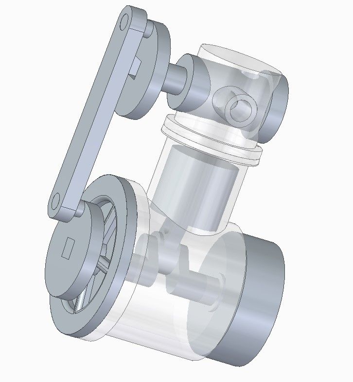
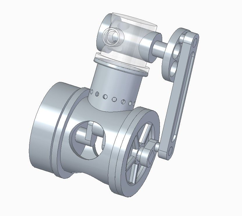
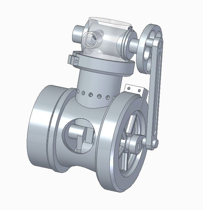
      Rethink is this single action engine, which I think has more possibilities:

      3deng.jpg

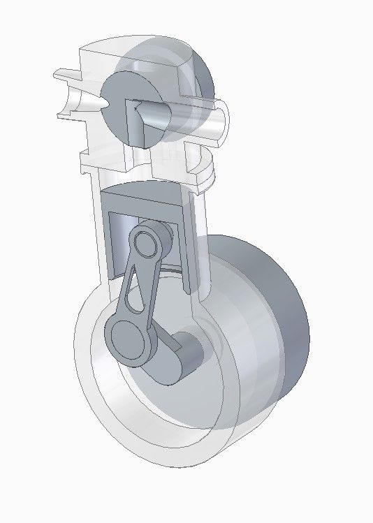
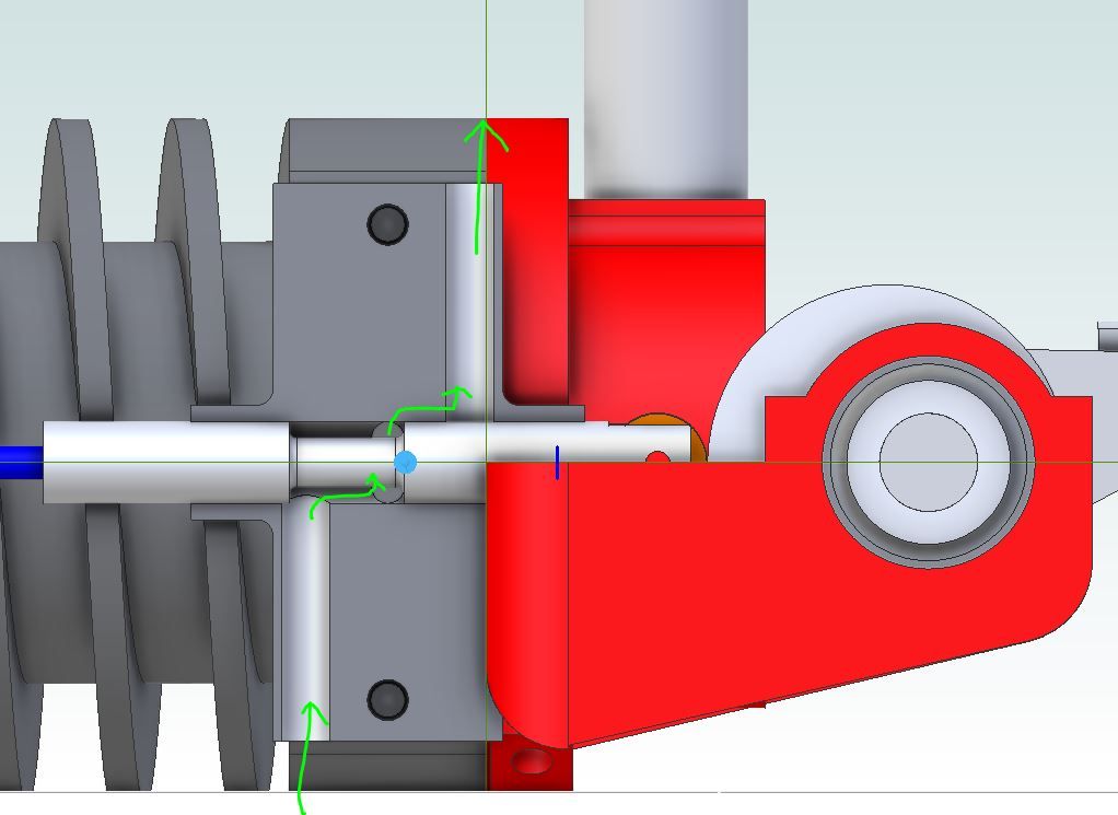
      Section:

      3dengsection.jpg

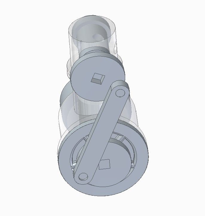
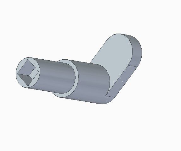
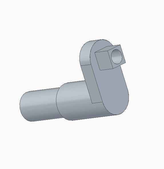
      CAD has already saved me from a mistake. I have the rotary valve driven by a cranked rod, which is no good because it can flip as it goes over the top, completely ruining the timing:

      3dengcrossed.jpg

      Now my next job is replace the cranked wheels with sprockets and design something like a bicycle chain that can be 3D printed.

      Lots of cause for concern already; friction is sky-high, there are no fasteners (I''m thinking plastic clips), the plastic isn't optimally proportioned, the valve can't fail to leak and the conrod has magically installed itself on the crankshaft.

      Already thinking a 3D/metal hybrid would be a much better bet but I'll persist with printed plastic for the time being.

      Comments and suggestions welcome! Yes it could be a step too far!

      Dave

      Advert
      #31704
      SillyOldDuffer
      Moderator
        @sillyoldduffer
        #601153
        JasonB
        Moderator
          @jasonb

          Single acting will be more prone to failing if friction is high as you are not pushing the piston back the other way as you do with a double acting. As your plastic flywheel won't have much energy to return the piston you could be in trouble.

          Simple piston valve may be easier driven by a push rod that runs against an eccentric cam.

          Race would be a bit of a no contest as I've already finished that enginedevil

          Edited By JasonB on 09/06/2022 19:48:40

          #601161
          DiogenesII
          Participant
            @diogenesii

            Is Jason thinking along 'Husky' lines – could be a plan..

            ..I was wondering about timing admission via a port on the crank, perhaps something like a monobloc (& oversquare?) 'River Queen'..?

            ..are you allowing yourself glue?

            Edited By DiogenesII on 09/06/2022 20:48:11

            #601162
            JasonB
            Moderator
              @jasonb

              No you need even more energy in the flywheel for across flow like the husky.

              Something simple with the piston valve opening an inlet and then as that is closed an exhaust port will be opened, timed so the piston does not have to compress any trapped air at the top of it's return stroke.

              The single acting "Woody" would be the sort of thing

              woody valve.jpg

              Edited By JasonB on 09/06/2022 20:56:26

              #601172
              John Olsen
              Participant
                @johnolsen79199

                NSU made a motorcycle years back that had the cam driven by connecting rods. but of course there were two of them with the cranks at right angles. Since it was a four stroke, there still had to be a two to one reduction gear.

                John

                #601188
                JasonB
                Moderator
                  @jasonb

                  Going back to your problem of the rotary valve going over the top, if you reduced the throw of the pin on the crankshaft so that you just get about 1/4 turn of the valve then that will be enough movement and it can't go too far. Same can be done with a double acting version like my Rocking Valve Filer & Stowe engine.

                  #601189
                  DiogenesII
                  Participant
                    @diogenesii
                    Posted by JasonB on 09/06/2022 20:52:37:

                    No you need even more energy in the flywheel for across flow like the husky.

                    Something simple with the piston valve opening an inlet and then as that is closed an exhaust port will be opened, timed so the piston does not have to compress any trapped air at the top of it's return stroke.

                    The single acting "Woody" would be the sort of thing

                    woody valve.jpg

                    Edited By JasonB on 09/06/2022 20:56:26

                    Yes – I get it – that's very economical of movement / friction..

                    ..interesting to read Woody again, that was a lot of offsets & handle-work..

                    #601215
                    SillyOldDuffer
                    Moderator
                      @sillyoldduffer

                      Diogenes : yes to glue, though slightly reluctantly! I'm open to other port arrangements too.

                      John: two cranks, yes

                      Jason's got me thinking.

                      • Single action means my flywheel needs to store enough energy to return the piston against a mass of friction and it's small and light.
                      • Sprockets are easy to 3D print, but when I got to roughing out the chain, I realised it's relatively heavy and full of bearing surfaces. Not a problem for polished metal, I suspect bad news for plastic links.
                      • I like the idea of rocking the valve by reducing the throw and it's a simple modification worth trying
                      • I also see advantages in a cam
                      • The 'Woody' valve is lower friction than my design

                      My first reaction to Woody was 'too complicated' but I'd reverted to thinking about making it in metal rather than printing it!

                      This will keep me quiet for a while…

                      Many thanks

                      Dave

                      #601224
                      Dave S
                      Participant
                        @daves59043

                        As your printing it it is no more effort to make a twin or even 3 cylinder engine.

                        This simplifies the double acting issue by making it a sum of singles.

                        something like a 3 cylinder radial might work nicely.

                        Have each cylinder somewhat like a CO2 engine – input valve at the top, exhaust through a slot at the bottom.

                        vale can be a simple ball and seat or some sort of print in place flap, triggered by a pin extension on the piston.

                        wouldn't be a 'traditional' engine, but then isntt that the point?

                        Dave

                        #601225
                        duncan webster 1
                        Participant
                          @duncanwebster1
                          Posted by Dave S on 10/06/2022 12:56:25:

                          ………

                          Have each cylinder somewhat like a CO2 engine – input valve at the top, exhaust through a slot at the bottom.

                          ……

                          Dave

                          This implies uniflow, which means lots of compression unless large clearance volume. You need a heavier flywheel for this. Proper exhaust valve better in my view

                          #601235
                          Dave S
                          Participant
                            @daves59043

                            Yep uni flow is what I meant. Given a 3D printed piston and 3d printed cylinder there is likely to be quite a poor seal, so the compression isn’t likely to be good.
                            Multiple power cylinders should help with the light flywheel issue

                            Dave

                            #601237
                            JasonB
                            Moderator
                              @jasonb

                              You could just do an oscillator and do away with the need for a valve. Easy enough to sand the two faces flat if print quality is not good. Double acting only needs an extra hole or two over a single acting one.

                              #601244
                              SillyOldDuffer
                              Moderator
                                @sillyoldduffer

                                Not much done – an afternoon of interruptions. However, I did manage to do Jason's rocking valve*, which doesn't get crossed over, increase the diameter of the flywheel and add exhaust holes at the bottom of the cylinder. I also realised the original crankcase had no vents, so the piston would have to compress air inside it in order to move. Now it's got big holes in it, which also saves plastic!

                                3drocking.jpg

                                Dave S' two cylinder suggestion is tempting. As can be seen it wouldn't be difficult to arrange the rotary valve and crankshafts to plug into each other creating an inline engine. Uniflow is harder to do, so I'd just run any add-on cylinders timed to be usefully out of phase with the others.

                                Dave

                                * Apart from the timing. My SolidEdge skills are unreliable, and the Relationships went haywire!

                                #601260
                                SillyOldDuffer
                                Moderator
                                  @sillyoldduffer

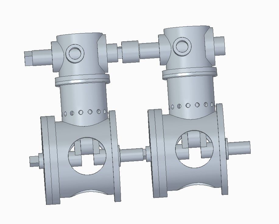
                                  Well. if this engine runs at all, it's not difficult to chain two, or more, of them together.

                                  3dengpaired.jpg

                                  #601281
                                  JasonB
                                  Moderator
                                    @jasonb

                                    A Vee or opposed layout may be better as you could run with just the same two bearings thus halving the friction on the crank. And don't forget if you do link them as shown then stagger the crank pins.

                                    #601286
                                    lee webster
                                    Participant
                                      @leewebster72680

                                      Dave,

                                      You said " Finish tends to be poor, with ridges and blobs. " Are you planning to print using FDM printer? Like my poor old Ender3? If so, what filament will you use? I do like the idea of a plastic printed engine!

                                      Many years ago I had an Airfix (I think it was Airfix) plastic beam engine powered by a small electric motor. It ran, and it squeeked like mad! I miss that little engine.

                                      #601303
                                      SillyOldDuffer
                                      Moderator
                                        @sillyoldduffer
                                        Posted by lee webster on 11/06/2022 08:05:59:

                                        Dave,

                                        You said " Finish tends to be poor, with ridges and blobs. " Are you planning to print using FDM printer? Like my poor old Ender3? If so, what filament will you use?

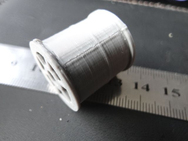
                                        Yes to FDM, I have an Ender3-Pro. Does a reasonable job and I should have put a scale on the 'ridges and blobs' comment, because they don't matter for many purposes. This is the worst bit of the cotton-reel example, which – to save time – was printed in low quality mode:

                                        dsc06604.jpg

                                        Low quality is 0.28mm. 0.12mm High quality, is roughly twice as smooth provided the printer and filament are tickety-boo.

                                        Low quality plastic finish is OK for most of the engine apart from the bearing and sliding surfaces. Unfortunately sanding and polishing them might still not be good enough. I don't know what the coefficient of friction of 3d printed plastic is.

                                        A hybrid engine would be better, such as designing in off-the-shelf roller bearings rather than scraping plastic on plastic, but I'm trying to stay pure plastic hoping I can make it work. I'll try ABS first because that's what I have, but combinations of other plastics would be superior.

                                        Another constraint: the printer's platform limits the size of the engine's biggest part. Have to keep an eye on that, unless I pay to have it printed professionally! While 3D-CAM opens many useful doors, the designer has to keep a close eye on production limitations; it's not difficult to CAD impossible to build assemblies!

                                        Before I go further I need to confirm SolidEdge will work with my printer! Should be OK, SE has an entire 3D section, but I haven't looked at yet and the proof is in the pudding.

                                        Unfortunately out today to fix my daughter's plumbing problem. When the kids were little, my life was dominated by buying them new shoes; then I became a teenage taxi-service; now they've left home I've been promoted to Bank of Dad and all-purpose handy-man. The latter has ruined my Alpha-male reputation – conclusive proof I don't know what I'm doing…

                                        Dave

                                        #601315
                                        martin haysom
                                        Participant
                                          @martinhaysom48469
                                          Posted by lee webster on 11/06/2022 08:05:59:

                                          Dave,

                                          Many years ago I had an Airfix (I think it was Airfix) plastic beam engine powered by a small electric motor. It ran, and it squeeked like mad! I miss that little engine.

                                          i made one of them too

                                          #601367
                                          lee webster
                                          Participant
                                            @leewebster72680

                                            Dave,

                                            I have 3D printed parts from SolidEdge using my Ender3. No problem.

                                            #601452
                                            SillyOldDuffer
                                            Moderator
                                              @sillyoldduffer
                                              Posted by lee webster on 11/06/2022 18:33:03:

                                              Dave,

                                              I have 3D printed parts from SolidEdge using my Ender3. No problem.

                                              Good news thanks, I'm getting close to printing the engine at half scale to see if it really does fit together. Might even run, though scaling down increases friction disproportionally .


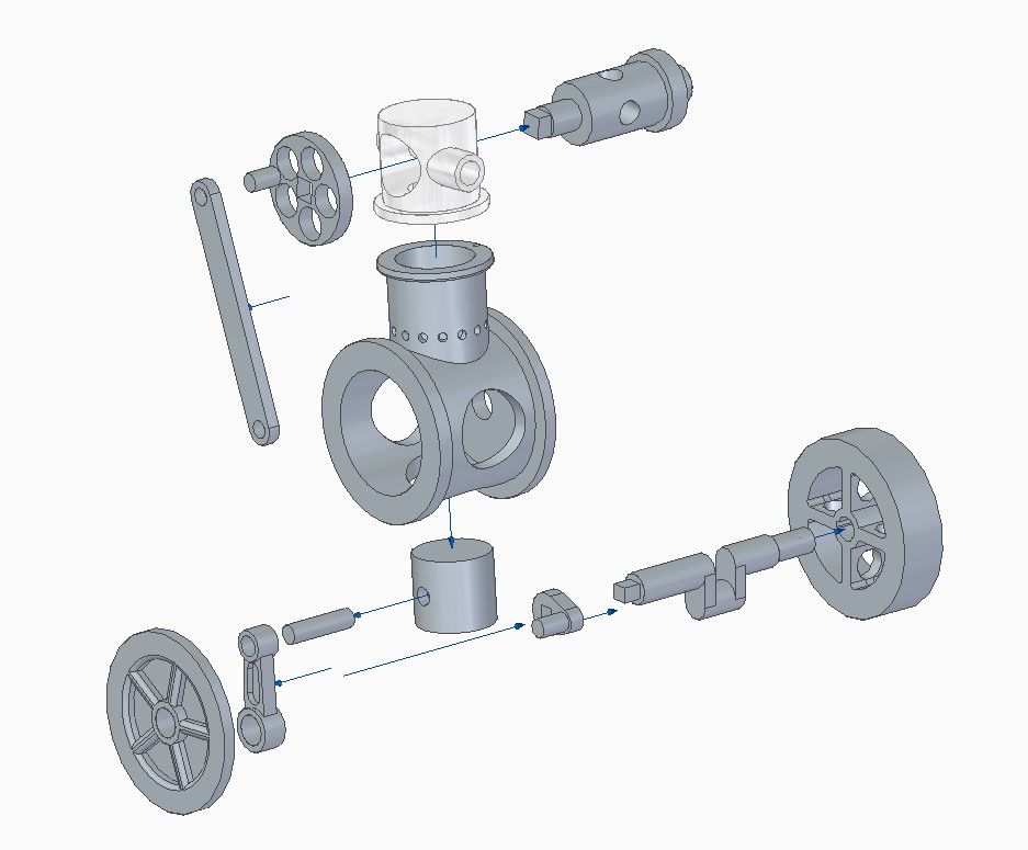
                                              3dengexploded.jpg

                                              All seems to fit together apart from the conrod and crankshaft: one of them needs to come apart so the two can be assembled together.

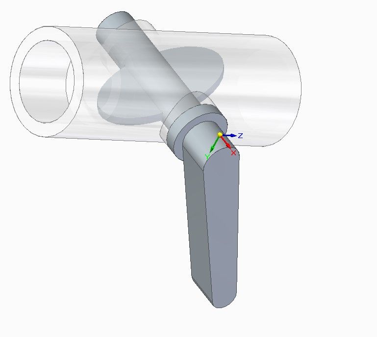
                                              Spent a good deal of today investigating a Solid Edge assembly-relationships problem. I designed this throttle valve, which animates OK except the flap rotates through the tube rather than the software recognising the tube is a physical obstacle.

                                              throttleinnards.jpg

                                              I've had several fights with Solid Edge where assembly relationships didn't work as expected, this latest being highly baffling because there are only two parts in it! They are related by an axial alignment between the through side hole and the tap shaft, and by a mate between the shoulders. The joint is set free to rotate. The handle's supposed to stop turning when the elliptical throttle plate hits the tube wall, and it didn't. A mystery because much more complicated relationships in the model work this way correctly. Very frustrating!!!

                                              Until now, the main issue has been me getting relationships wrong due to not quite understanding how SE works. This one wasn't obvious – eventually identified the problem was a tiny geometry error in the through hole. I created one side manually and patterned the other from it, supposedly a 180 degree mirror image of the hole and shroud. Not sure why but the two sides were slightly misaligned, so the tap shaft was out of alignment across the tube. Tiny but enough to confuse Solid Edge's boundary calculations. Lesson learned: if relationships won't bind or behave strangely, double check the part geometry. Geometry has to be right, not nearly right.

                                              Dave


                                              Edited By SillyOldDuffer on 12/06/2022 15:55:40

                                              #601708
                                              SillyOldDuffer
                                              Moderator
                                                @sillyoldduffer

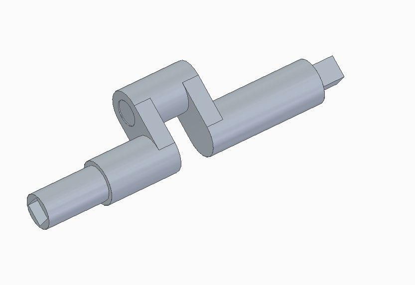
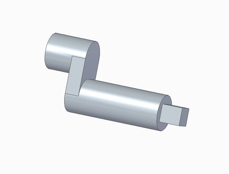
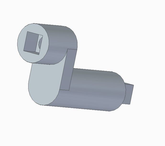
                                                Slow progress with the engine, mainly because I keep stopping to solve new CAD problems. The latest is I needed to split the existing solid crankshaft in two so the crank can be fitted.

                                                cranksolid.jpg


                                                crankrearpart.jpgcrankfrontpart.jpg

                                                Then the two parts changed to fit securely back together:

                                                crankfrontspigot.jpg

                                                crankrearspigot.jpg

                                                Easy when you know how which I didn't! Quicker to have remodelled the crank in two parts from scratch, but breaking a part into bits and then editing them separately seems a handy skill. After a few hours cursing and crashing SolidEdge, I got there. The second attempt took a few minutes, no swearing, and nothing broke.

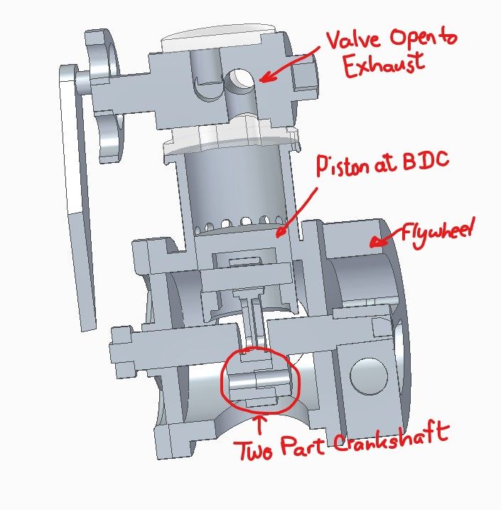
                                                The latest section shows the engine is nearly ready to print, valve position roughly right, and the parts should fit together. The main thing missing is the fasteners needed to hold it all together. I'm also inclined to put a lot of holes around the periphery of the flywheel that can be loaded with modelling clay or tungsten putty to store more energy. Another useful change might be to taper the rotary valve to improve the seal. Finally, I can save a lot of fettling by opening up parts that plug together. Expecting a 4mm printed plastic shaft to slide neatly into a 4mm printed plastic hole is too much! I also want to see if a 4mm nut and bolt to hold the crank together can be printed: the normal metric pitch is too fine, and I'll probably have to go coarser to suit the material – Whitworth!!!

                                                e3dengwithtwopartcrank.jpg Dave

                                                Edited By SillyOldDuffer on 14/06/2022 14:43:28

                                                #601918
                                                SillyOldDuffer
                                                Moderator
                                                  @sillyoldduffer

                                                  Despite being out this afternoon, I got closer to finishing the engine design, and was able to take a peek at the next stage – printing it!

                                                  Not quite finished but the engine is now held together by clips. Not entirely happy with them and I might look for alternatives. The nut and bolt needed to hold the crankshaft together aren't started at all, and I have grave doubts about them.

                                                  3dengassywithclips.jpg

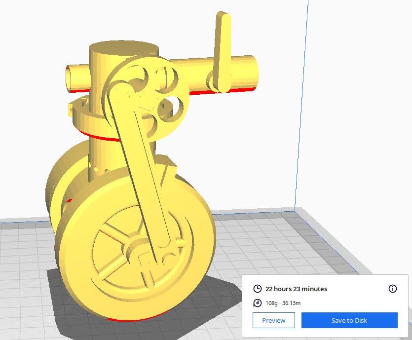
                                                  Solid Edge's 3D print functions seem straightforward except the first test export resulted in a tiny plastic model – 2.8 x 3.7 x 4.7mm. Naughty, bad Solid Edge. Despite the model being metric throughout, Solid Edge defaults 3D prints to inches and has to be ordered to use millimetres. That fixed, Cura loaded the model correctly.

                                                  3dengassycura.jpg

                                                  However, Solid Edge can check the design, and now I have to look at the complaints! For example, next image shows all the areas of my model where the plastic skin is less than the recommended 2mm thick, which would cause structural problems. The deliberately thin for lightness piston is the worst, but the flywheel, head and parts of the crankcase need attention too.

                                                  3dengtoothin.jpg

                                                  Another worry, although Solid Edge and Cura both accepted me printing the whole engine as a complete Assembly, I'm far from convinced it would work. Cura says the model will take 22 hours and 23 minutes to print, and I fear ending up with a clump of parts stuck solidly together. Love to believe a complex assembly of parts can be printed in one go, but I think it much safer to print the parts one at a time so they can be fettled as necessary to fit and move smoothly. Also be good if two or more parts can be printed side by side to save time. More research needed – I'm out of my depth again.

                                                  Dave

                                                  #601928
                                                  lee webster
                                                  Participant
                                                    @leewebster72680

                                                    With printers such as my Ender 3, putting more than one part on the bed for printing saves very little time. The only time saved is how long it takes you to get one part off the bed and telling the printer to print the next file. If you had a resin printer the story would be different. Printing say six parts, all on the bed at once, would take the same time as printing one. That and the improved quality of the finish is why I am thinking of buying one.

                                                    I wonder if a disc valve would have less friction than a rotary, tapered or not, valve? They seem to work well on my bathroom taps!

                                                    #601966
                                                    SillyOldDuffer
                                                    Moderator
                                                      @sillyoldduffer
                                                      Posted by lee webster on 15/06/2022 23:24:23:

                                                      With printers such as my Ender 3, putting more than one part on the bed for printing saves very little time. The only time saved is how long it takes you to get one part off the bed and telling the printer to print the next file. If you had a resin printer the story would be different. Printing say six parts, all on the bed at once, would take the same time as printing one. That and the improved quality of the finish is why I am thinking of buying one.

                                                      I wonder if a disc valve would have less friction than a rotary, tapered or not, valve? They seem to work well on my bathroom taps!

                                                      I was hoping to save the bed heating and cooling time which is significant when printing lots of small parts, but this engine is all medium sized parts, so you're probably right.

                                                      I've started to worry about the material properties of the various plastic filaments and FDM generally for printing anything that needs to be strong. For example, because the print is developed layer by layer, parts have a grain like wood, and are probably weaker up down than across. So for strength something like a conrod should be printed flat, not upright. Unlike model engines fabricated or made from metal castings, where the strength of the metal makes careful design unnecessary, I'm pretty sure plastic needs careful geometry – thick plastic at weak points and thin plastic everywhere else.

                                                      All your fault Lee. As a result of your comments, I've been looking into Resin printers! Can I send you the bill please?

                                                      Only reason for me going for a rotary valve is they're simple to design.  Unfortunately, there's a lot of friction, and it may not work!  

                                                      Dave

                                                      Edited By SillyOldDuffer on 16/06/2022 10:15:16

                                                    Viewing 25 posts - 1 through 25 (of 40 total)
                                                    • Please log in to reply to this topic. Registering is free and easy using the links on the menu at the top of this page.

                                                    Advert

                                                    Latest Replies

                                                    Viewing 25 topics - 1 through 25 (of 25 total)
                                                    Viewing 25 topics - 1 through 25 (of 25 total)

                                                    View full reply list.

                                                    Advert

                                                    Newsletter Sign-up