Hi all,
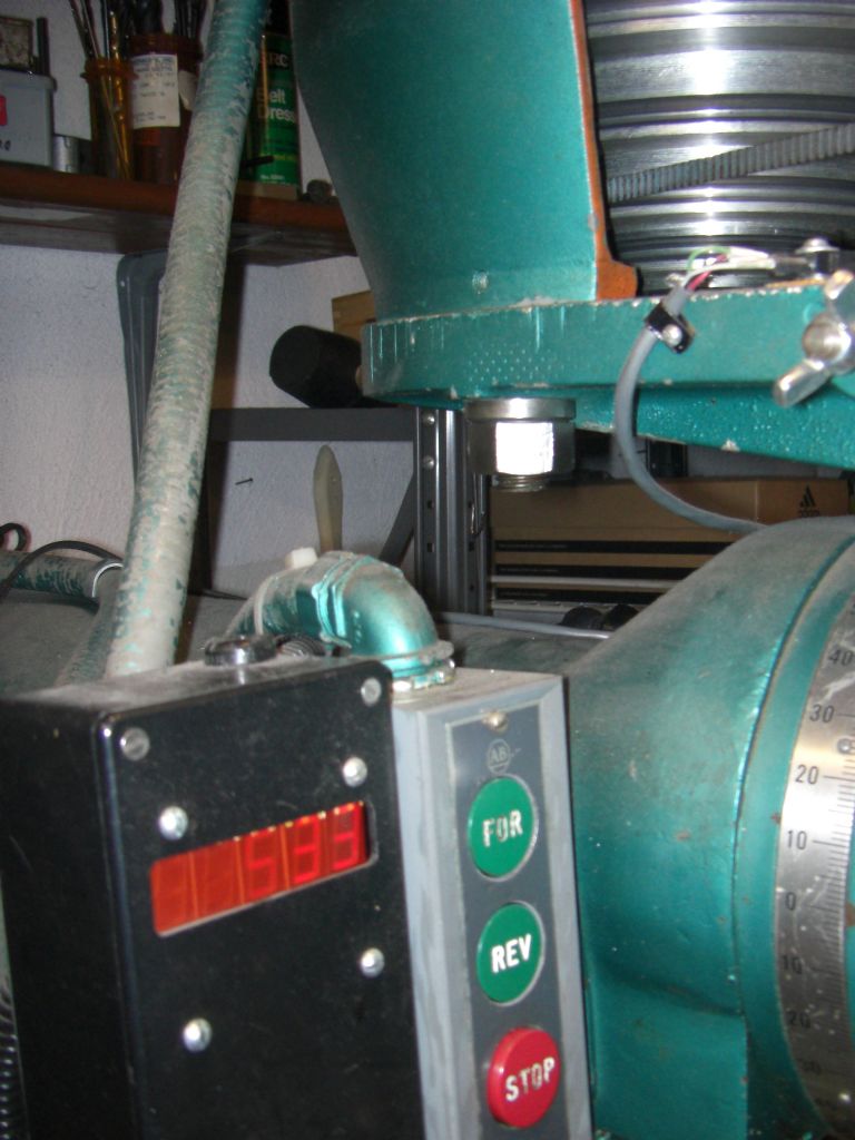
Just noticed this thread, and unfortunately not able to thoroughly read all the items, but I though you might be interested in this. I have uploaded some photos of two versions of a tachometer I built back in 2002, using essentially the same idea: a PIC with a sensor and LED displays. I intended to market the devices in several forms, but never did. I built two prototype versions. This is the first one:
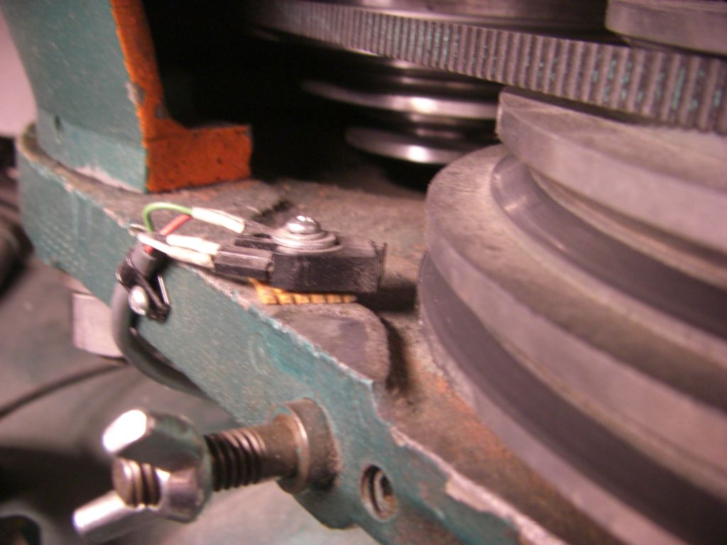
This shows the tacho mounted in a large black box to the side of my Millrite mill, doing 533 RPM under VFD control. The display is a set of 5 reasonably large LEDs,and the sensor can just be seen top right just above the wing nut. Here is a closeup:
The sensor is a reflective all-in-one device with included Schmitt trigger, so interfaces directly to a PIC data input port. The reflective element is the bottom part of the bright aluminium spindle pulley, which. I covered approximately half of the circumference with matt black crepe self-adhesive tape, so we are getting one pulse per rev.
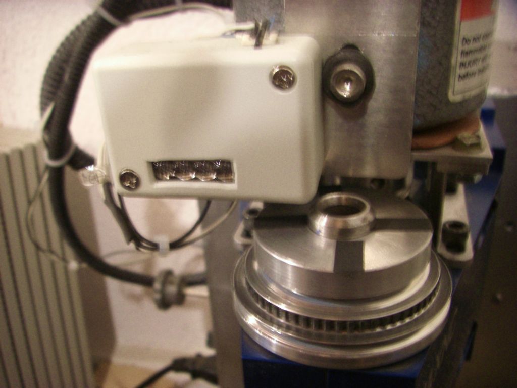
This is the second prototype:
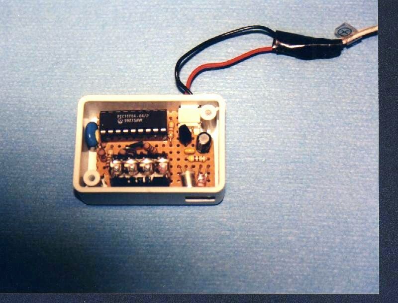
It is much smaller. The box is 2-2/8 x 1-3/8. There are four pulses per rev in this case, given by four strips of crepe tape on the top of the MAXNC spindle pulley. Here is the inside of the box:
The display is a stick of four 0.1″ LED digits. These were bought in 1972 and are impossible to find today. I did a design using the smallest available displays, and it would just fit in this box, along with the PIC, the regulator and the sensor. The sensor is also reflective, but using separate LED and detector, but again one with a Schmitt trigger built-in.
The real secret is the software in the PIC. The algorithm is quite sophisticated. The input from the detector (1 or 0) is sampled at at least four times the maximum input frequency. It is then digitally filtered to provide smooth edge events. Following that, the period between events, or events per period, is measured and used to determine if there is movement (for display blanking), and a further digital filter and scaling unit provides the measured speed in the desired units. The unit self-adapts to measure the frequency at high RPMs and the period at low RPMs. This provides a stable display with a reasonable response time and resolution.
It turns out that you do not need many pulses per rev. One is enough for the Millrite, though I used four on the MAXNC because there was more noise from ambient light and because the sensor is inferior. Any more caused problems with the sampling rate, though it is a slow/old/small PIC (16F84). However, you cannot just measure the period of each pulse; you do need some decent filtering, or the display tends to be garbage, jumping all over the place. It is worse with more pulses per rev, because of the unevenness of the reflective areas (unless you want to use an expensive encoder-quality rotor instead of black tape).
As a further project, I took the raw output from the sensor to a closed-loop motor control chip. I would have liked to pre-process it in the PIC first, but not enough pins. This worked well, giving full torque from the MAXNC motor down below 200 RPM. Ideally, the PIC should control the motor directly. I also fed it to my EMC2 CNC software to (eventually) provide closed-loop CNC speed control, but unfortunately it needs more work on the PC side before it can be useful.
Alex gibson.


