Having recently bought the SX2p Mill from ARC one thing i didn't like was having to get the little tool to lock the spindle. Seen some ideas on the net, but mostly they are for the gear driven ones where they have a plunger on the top.
Whillst doing the design in Freecad i thought why not include a rev counter also.
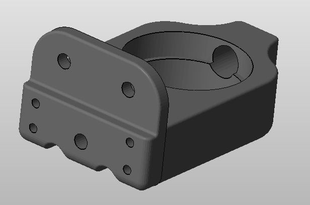
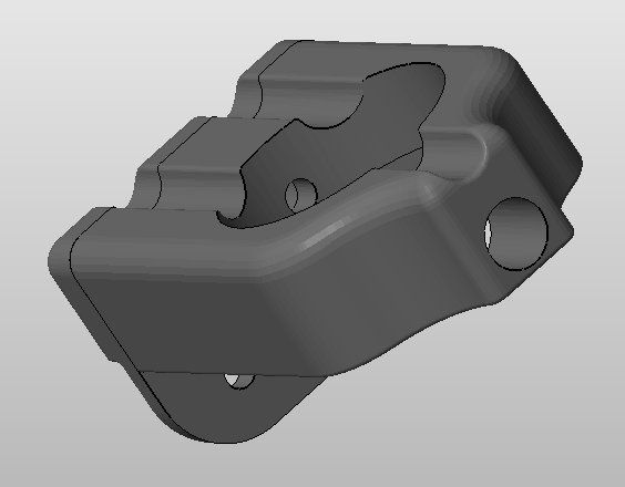
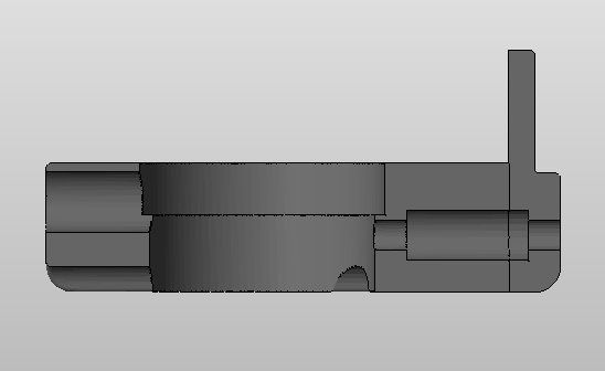
The first thing i did to the mill was remove the plastic shield, ideally i wanted to use those. I came up with this..
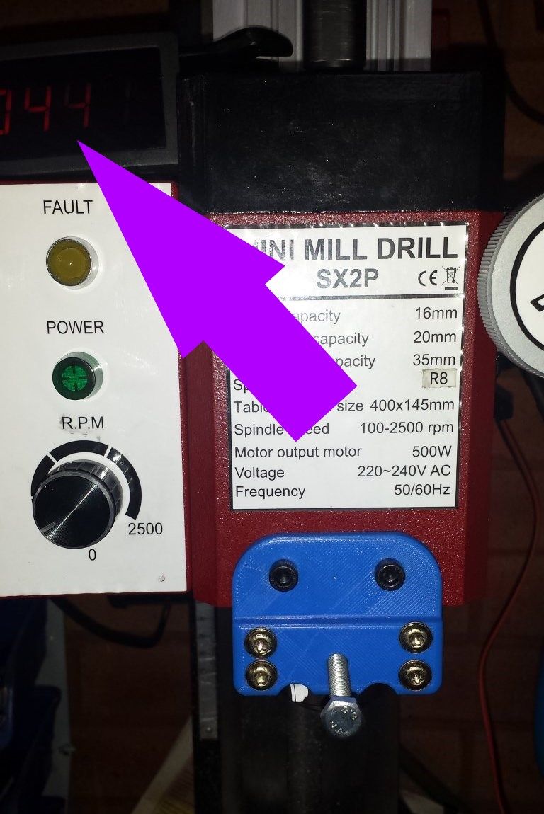
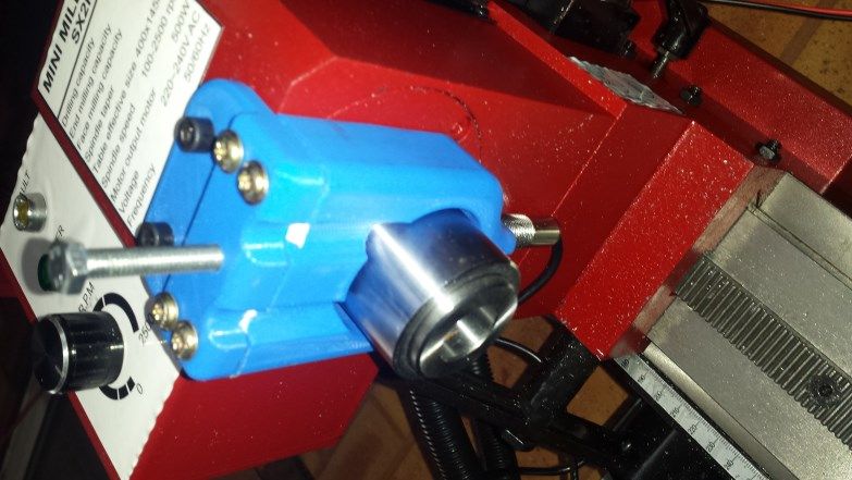
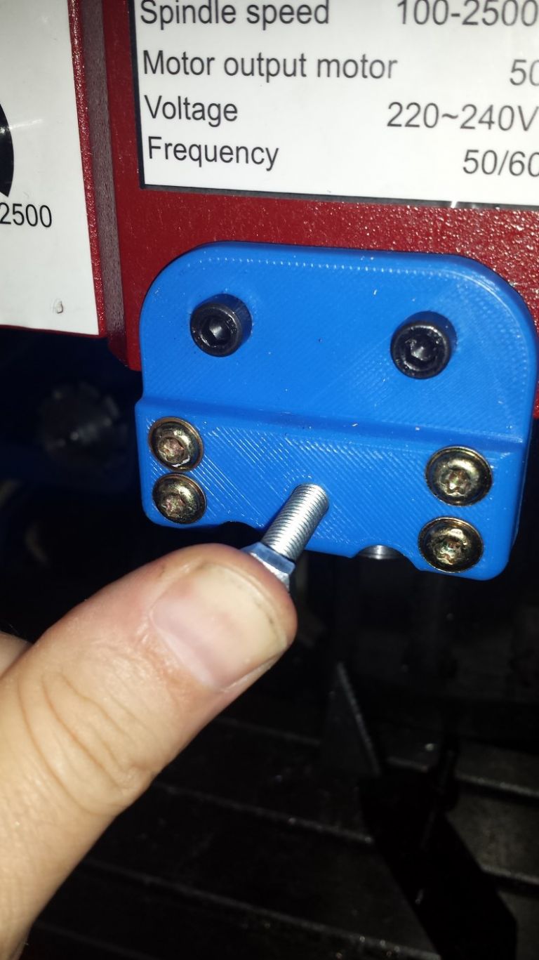
And in practice, this is what came out of the 3D printer…. Sorry for the poor pictures, you can almost see the LCD RPM readout on the top. I have not made a case for that as yet. Its just perched there.
Very little visibly wiring when its done, i may power it off an internal battery?
Bolt on the front pushes in to lock the spindle, one thumb required, spring internally ensures the bolt cannot stay engaged. Just a temporary setup a proper hardened rod will be used.
Rev counter probe fitted into the rear. Magnet glued to spindle, well in theory.. My glue didnt hold it?
Mounted using the 2 guard fixing bolts. Not other holes required.
Anything wrong with my setup? Have i missed something
Yeah it just started out as how can i lock the spindle without drilling holes in the new mill. The front 2 fixing screws were an obvious choice because the first thing i did was remove the guard. I just stand that on the front plate to deflect the chips. I always wear eye protection, safety glasses for quick jobs and a full face shield for jobs where the glasses tend to steam up.
I may have a little idea forming, i will email you in a couple of days. Not used to writing articles though, too many years on the internet and bad habits have set in
there Maybe no capitals or in the Wront places, And Full stops are on a strict diet
PS. Did i mention im lazy and only like starting jobs and not finishing them?
Edited By Dave Smith the 16th on 09/07/2016 02:00:49
My spindle lock tool sits on top of the control box, just where your purple arrow is pointing ( the drill chuck key sits there also). A small Manet will keep them there if you tend to misplace them.
Curious as to how well this performs for tightening/loosening the drawbar.
My main concern would be that the plastic might split by the two mounting mounting screws on the front, however my concerns may be unfounded.
If made available for download, the STL files would be good for the MT3 versions of this mill.
The R8 version, as sold in the US, has the spindle lock hole sllightly lower down.
I know this because I swapped my spindle from MT3 to R8 – here are the two spindles side by side for comparison:
The larger hole in the R8 spindle is for a pin to locate in the R8 slot – not supplied with the spindle, and more hassle than it is worth if fitted anyway.
I think i did purchase an R8 to ER32 collet holder. Bought a full set of ER32 collets (1mm to 20mm) i think
for less than £50. I only opened one to have a look and it seemed very good and probably more than accurate enough for my needs.
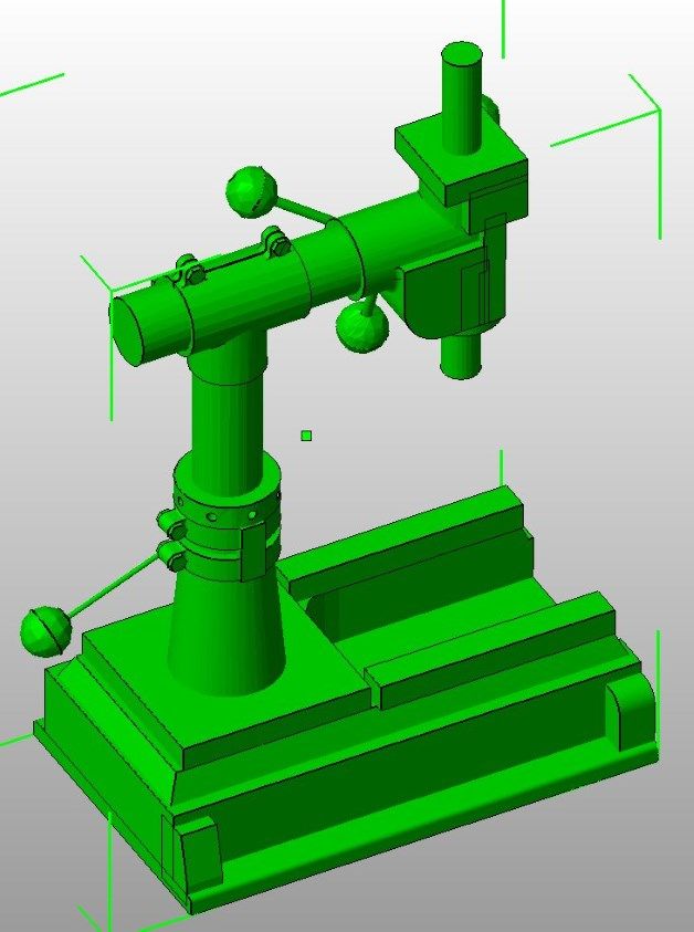
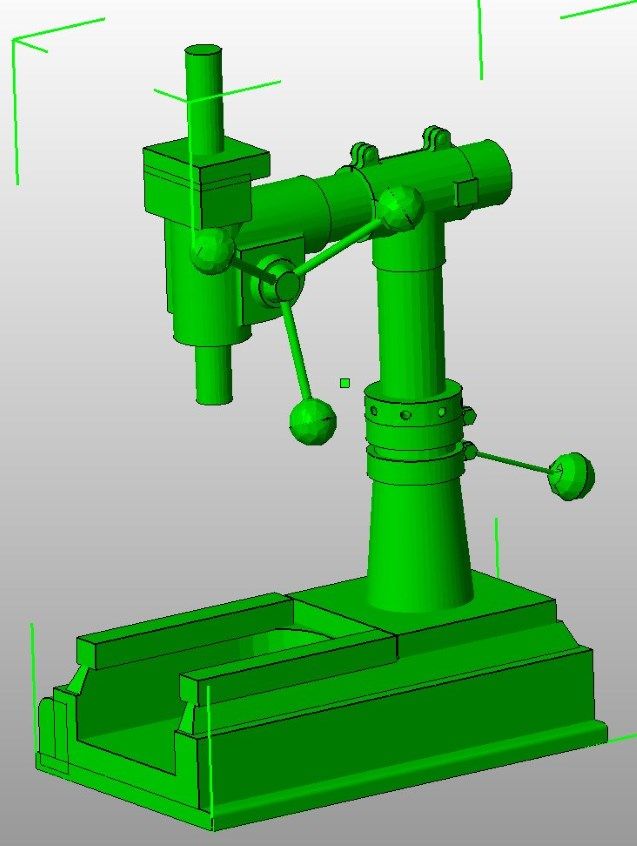
Having a play with freecad and just using the part editor with basic shapes got this.. Only working from images on a google search which is tricky because there appears to be many different versions.
Author
Posts
Viewing 14 posts - 1 through 14 (of 14 total)
Please log in to reply to this topic. Registering is free and easy using the links on the menu at the top of this page.