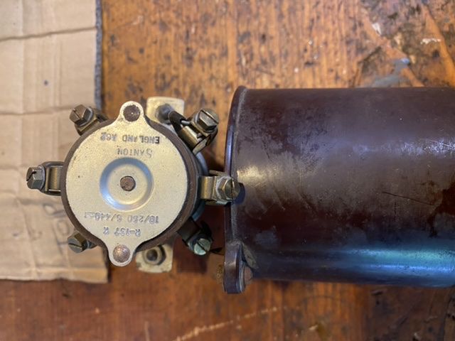
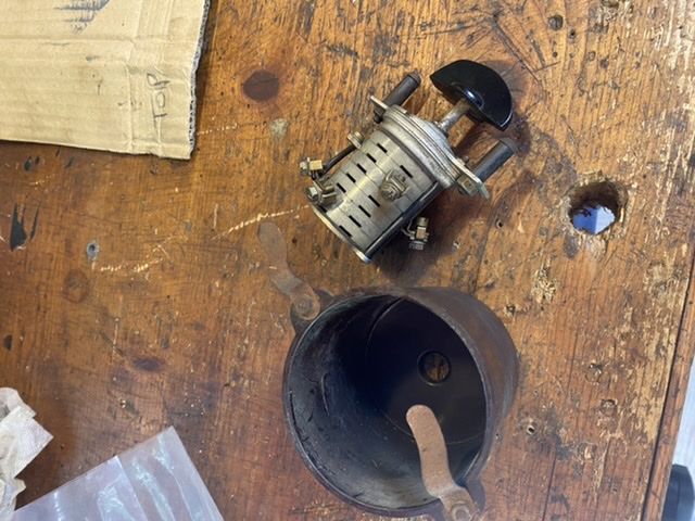
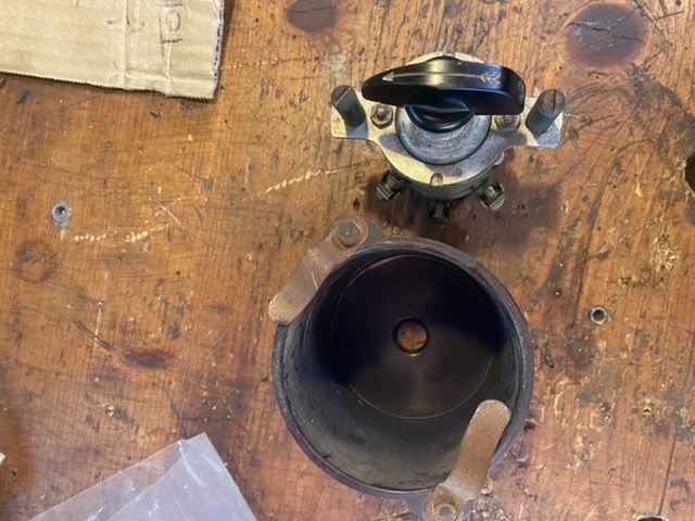
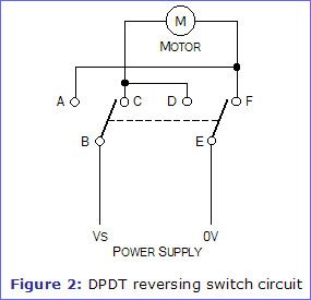
Here is some information on a Santon switch that someone was using with a Myford. It may not be the same as the Santon switch that you have but you can meter out your switch to see if the contact layout is the same as the one in my notes.

This is from a thread that was probably around 10/03/16 (When I uploaded the picture to the forum.) or 29/09/14. (The date of the file on my computer.)
These are the notes that I uploaded to the thread,
Information on Santon switch which is sometimes fitted to Myford lathes
This is how I understand the switch works.
Forward B to 2, C to 1, A to 3
Reverse B to 2, C to 3, A to 1
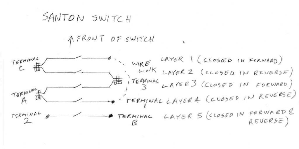
I have been looking at the way the switch works. There must be 5 contact sets. Each contact set is on a layer of the switch. I will call the front layer layer
1. Terminals C, 3, and A are actually connected to 2 layers each. (You can see the metal connections from 2 adjacent layers bent together.) Terminal C
goes to layers 1 & 2. Terminal 3 goes to layers 2 & 3. Terminal A goes to layers 3 & 4. The contact that I expected to be closed in the for forward position
of the switch (Terminals 3 and A)
Layer 1 Terminals C (and 1 via a wire link) (Closed in forward.)
Layer 2 Terminals C & 3 (Closed in reverse.)
Layer 3 Terminals A & 3 (Closed in forward.)
Layer 4 Terminals A & 1 (Closed in reverse.)
Layer 5 Terminals 2 & B (Closed in forward & reverse.)
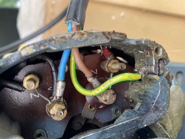
Wires from motor to switch
Start R
Start S
Run U1
Run U2
Santon reversing switch connections.
1 To motor start terminal (R ?)
2 Live in
3 To motor start terminal (S ?)
A Live in
B To motor run terminal (R ?)
C | Neutral in
| To motor run terminal (U1 ?)
Where the above connection shows start terminal it means the start winding in series with the centrifugal switch and start capacitor.
Les.
Edited By Les Jones 1 on 05/07/2022 20:16:39
Les Jones 1.


