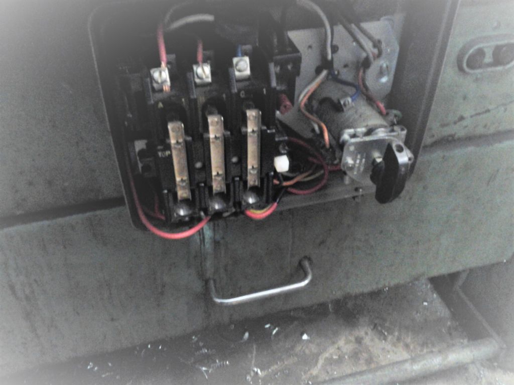
Harvest has intervened, and my electrician has been hard pressed. So motor not wired, but it is installed.
Please can I ask another question concerning the 2 speed motor wiring?
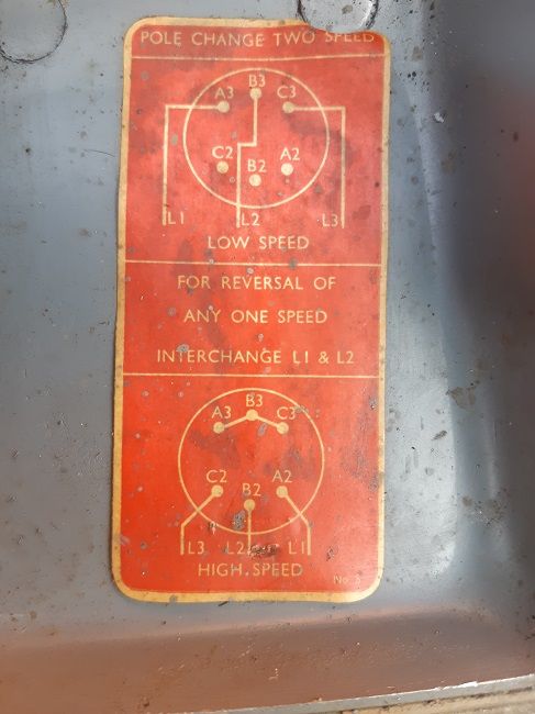
Here is a diagram from the motor. Does the connection instruction for the High Speed, the lower of the two diagrams, imply that when L1, L2 and L3 are connected to A2, B2 and C2,, A3, B3 and C3 are connected together?
I dont really understand how they are not connected together (for obvious reasons) in Low Speed, but are in High Speed. Does this have to be done in the switch? Thanks for guidance.
I have the Broook Motors book on Induction Motors (my father worked for them his entire career).
Pg 199 show precisely the wiring which Tom posted above. It is possible to wire up a star-delta switch to perform the two speed switching. Everything else can be left alone: the switch is interposed between the output of the existing contactor and the new two-speed motor. I can post a schematic if you're interested.
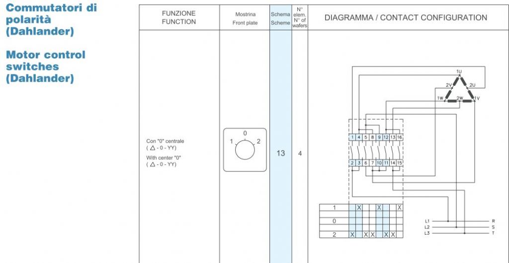
There's a supplier in Italy selling a star-delta rotary switch at a reasonable price
Common cam switches are fine for such duties too and may be less costly, maybe £5 to £15 range, depending on contact arrangements and whether they can be got naked without knobs, faceplate et al.
Connection layout for a cam switch at VN P11, top left, on this link **LINK** albeit with an off position in the middle which you don't want. Very expensive supplier!
Last cam switch I got was for a Bridgeport varispeed with a rather more complex set of connections. Took a deal of figuring out but I was able to find a standard part number rather than go the build your own route. Easily done but buying the bits separately comes a bit more expensive.
If you do use a common cam switch take care not to operate it with the motor running. Bade for the motor and terminal for the switch unless you are very lucky. The original on the a forementioned Bridgeport switch had sufferend in that way and been "creatively" reconnected so the machine could still run!
I have the Broook Motors book on Induction Motors (my father worked for them his entire career).
Pg 199 show precisely the wiring which Tom posted above. It is possible to wire up a star-delta switch to perform the two speed switching. Everything else can be left alone: the switch is interposed between the output of the existing contactor and the new two-speed motor. I can post a schematic if you're interested.
Hi John
It would be helpful to see the Brook motors schematic for the motor wiring if you can upload it.
Emgee
As Emgee says, John, it might help my cause (I need all the help I can get!).
If it is possible for you to upload a diagram it would be very interesting.
Having re-examined the Lovato switch data which I mentioned above, it appears that many of the change-over contacts are internally linked, so can't be used as such.
However, on the Lovato website there is a comprehensive list of their motor switches, and there is a three-postion pole-changing switch which does the job: it's schematic 13 and the switch reference is
GX1613U
There's one on ebay at the moment. You could tackle this with a cheaper / simpler switch but you'd then need additional contactors and both the cost & size would escalate.
I've scannned 40 pages of the Brook Motors book which include multiple motor configurations and the schematics of the old Brook control gear. There's a lot more data on their range of motors from the 1960's back, if anyone needs such info.
Given that contactors are relatively cheap these days consider fitting a simple change-over switch to control the actuator coils of a pair of contactors. One contactor carries the wiring for high speed and the other the wiring for low speed.
Big advantage for the novice or occasional electrician is that all the wiring arrangements are visible so its easy to trace and verify that its right. No teensy moulded plastic connector identification numbers to struggle to read whilst hoping the invisible innards of the switch are what you think they are.
Standard font for instruction leaflets seems to be 6 point. Not very mature eye friendly. If you get a leaflet. Modern trend seems to be to print on the inside of the box. Dark grey on grey.
Once again so many ways this can be done , Wish I had Toms Motor on a bench with a few contactor;s so difficult to find the easiest way when you are not there the obvious and easiest is always the last idea that works A simple change over switch and 1 Relay for Slow and 1 for Fast..
I am not into taking photos but I find the camera on an iPhone very useful for taking a picture of motor plates in difficult to view positions or any other info label for that matter, the zoom on the photo viewer is very handy if I haven’t got my eye crutches with me. Useful in shops too if you want to read a product label. Can be useful for wiring but not always clear where a wire goes so swap one at a time if possible or make a drawing. Lots of specs. now don’t fit wire numbers so Numbered multicore not too bad but panel wiring all same colour and no labels.
A three phase motor has 3 leads , connect each of your phases one to each lead and your motor will run if this runs o/k it may be running either slow or fast , which ever it is this will tell you which speed it is running at.
If the direction is wrong change over two of your incoming leads to reverse rotation. al O/k St test complete
disconnect your incoming supply and then reconnect to the other 3 leads your motor will either run fast or slow
2 test complete.,
Your Motor has two sets of windings one for slow and one for fast .
Hope this makes sence if not please come back regards Brian
A three phase motor has 3 leads , connect each of your phases one to each lead and your motor will run if this runs o/k it may be running either slow or fast , which ever it is this will tell you which speed it is running at.
If the direction is wrong change over two of your incoming leads to reverse rotation. al O/k St test complete
disconnect your incoming supply and then reconnect to the other 3 leads your motor will either run fast or slow
2 test complete.,
Your Motor has two sets of win
or fast .
I get that, and that is the kind of "walk him through it" instructions I need!
BUT, according to the motor wiring diagram, you have to link the low speed posts together while in high speed.
Hi Tom Are the following linked together A1 B! C! if so you may have a dual voltage motor , Is there anyone in your area who does motor repairs ? I feel if you take this motor into ther works they will be able sort this out quite easily.
I think Tom has this sorted . We've established that it's a pole-change two-speed motor, which required a slightly specialised switch to be interposed between the DOL starter & the motor.