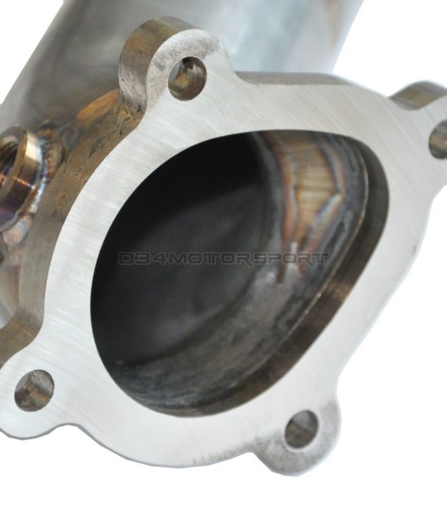
Ant, the flange assembly in the photo, looks suspiciously like the turbine outlet / exhaust front pipe for a turbocharger, and the ‘Egg’ shape formed to accommodate the gasflow from both the turbine outlet and a wastegate valve.
My guess for commercial applications, is that a press would be used similar to that used for making brake pipes.
The pipe would be clamped in specially constructed ‘Female’ split jawed jig, then a similar ‘Male’ press tool would be pressed into it – either by mechanical or hydraulic means.
Also possible that the flange is made as a separate component, then welded to the pipe end, which would simplify manufacture of the flange and press tools.
Back in the late 1970’s I was manufacturing turbo systems for automotive applications.
No one other than SAAB or Porsche had a turbo car on the road at that time, so everything had to be hand made, and the turbo’s & wastegates sourced from anywhere they could be had.(IHI, RayJay, KKK, etc).
Flanges had to be made to suit individual turbo types, and then adapted to fit standard manifolding, or a complete manifold made.
The flanges were generally flame cut from sheet steel (one offs) or cast iron to pattern for quantity, then finished by hand.
Pipe bends were available in various diameters, which then had to be shaped to the flanges similar to that shown above.
Generally, I just got the pipe end red hot, and hand beat the pipe end into shape to suit the flange, then when happy with the shape, trim the end with a grinder and electric (stick) welded together.
I never had one come apart, and those things used to get white hot on the dyno!
I’ll upload some photo’s of a Porsche 911 I did in 1980, also have some of a Mini 1100 Special, Landrover and other gear somewhere.! (long time before digicam’s unfortunately)!
Best regards
John
RJW.


