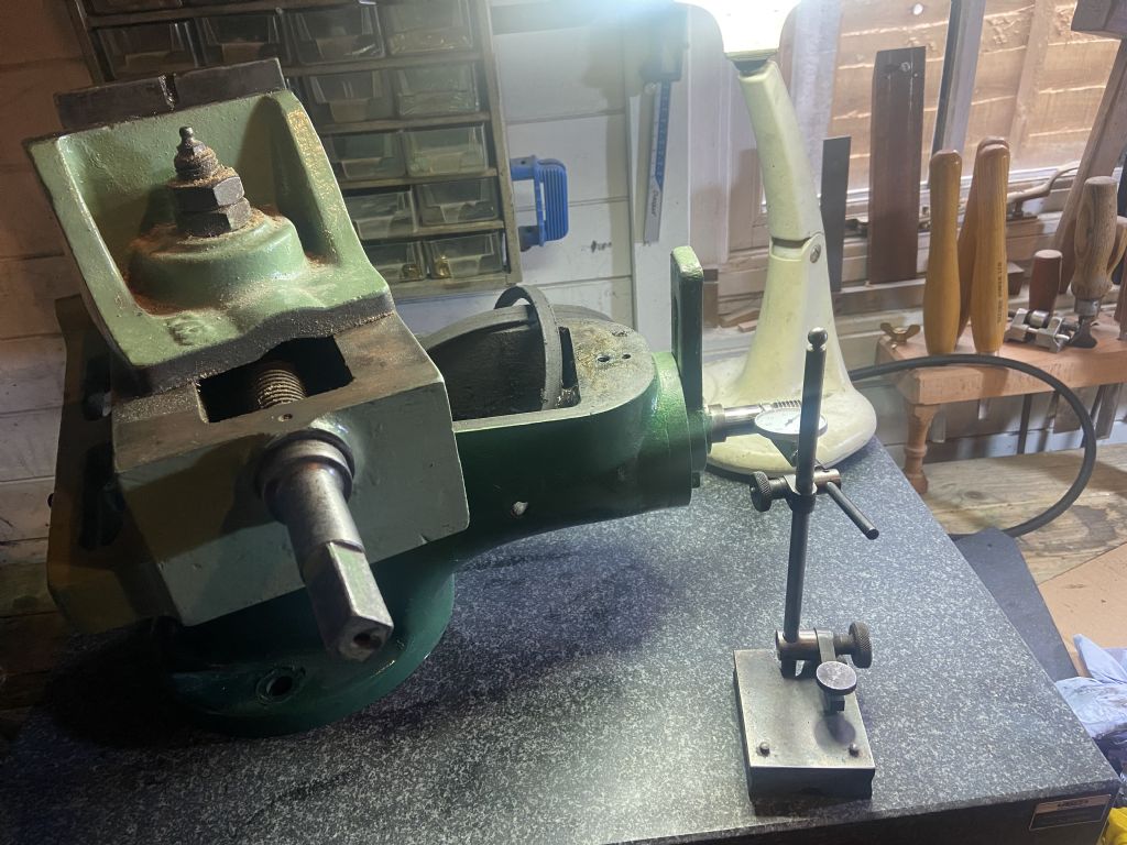
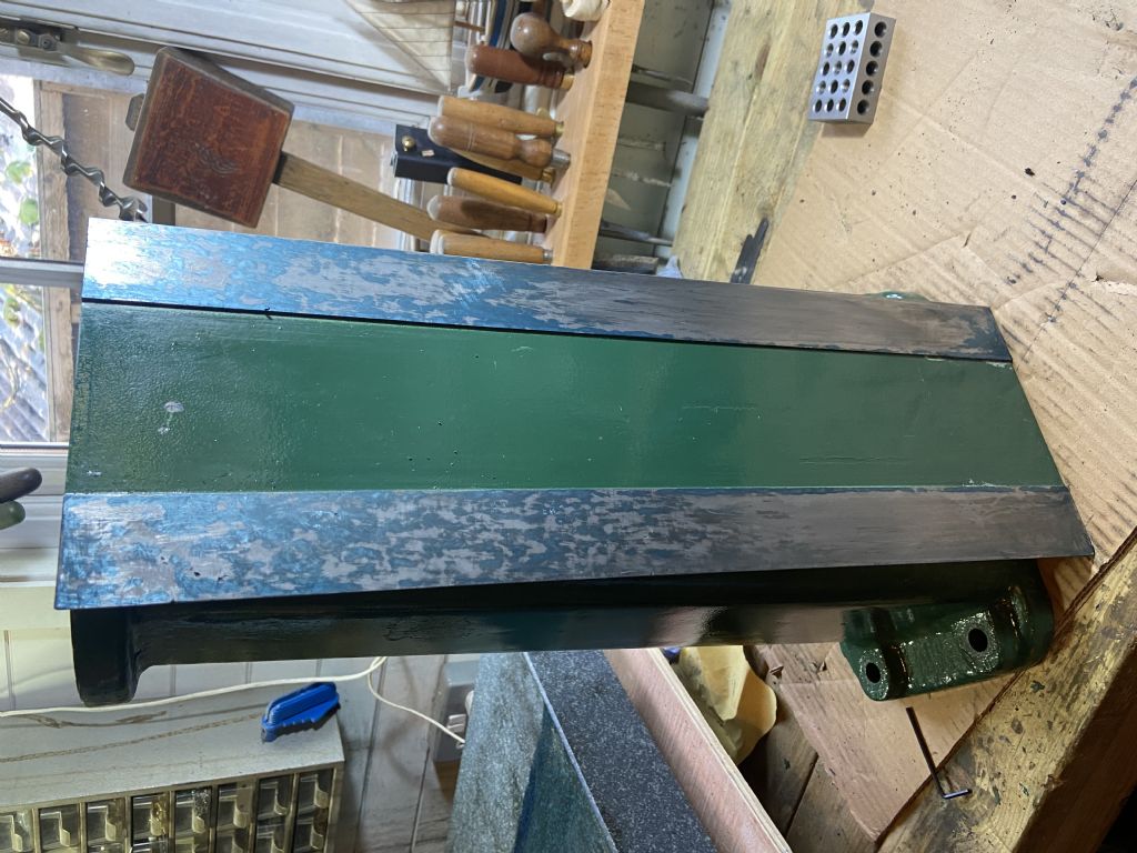
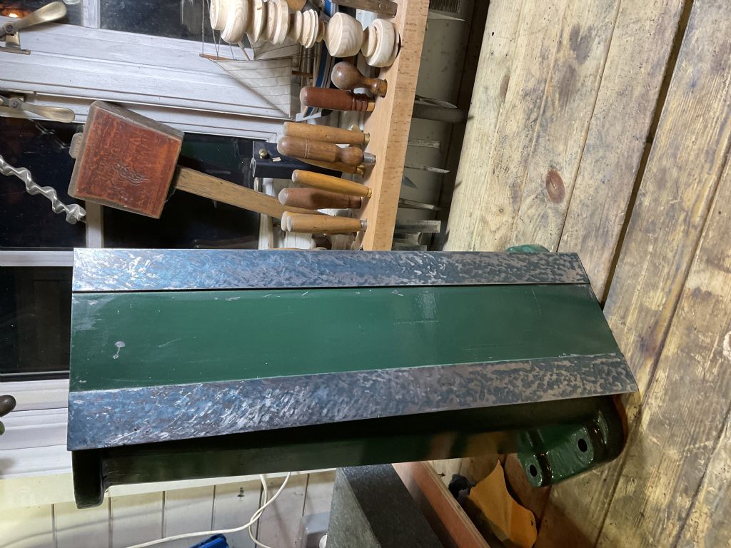
Steve, your explanation is fine; the problem is that we're coming at this from different directions and run the risk of talking at cross purposes. Also, according to my wife, I'm capable of misunderstanding the simplest of things. BTW, I note the nice granite square!
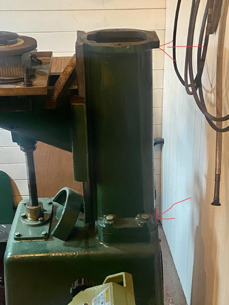
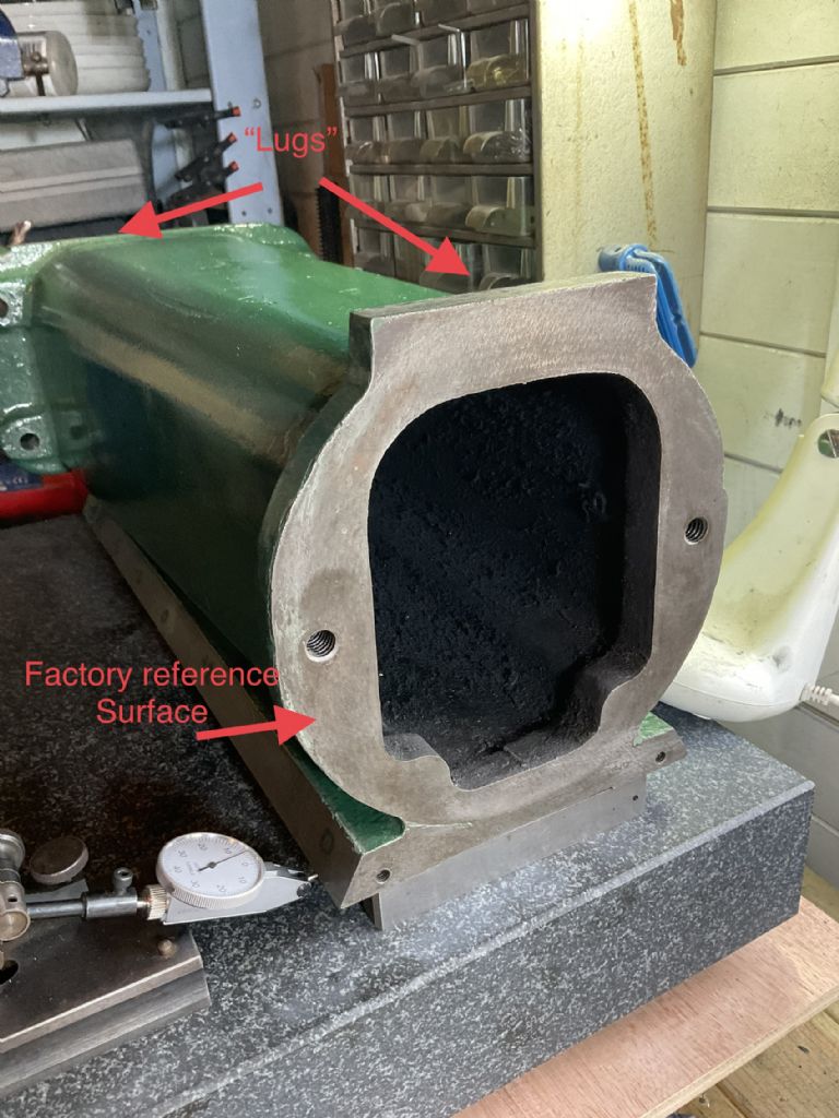
The fundamental difference in our points of view is that I believe your 'factory reference surface' (FRS) is a poor choice for a plane to which everything else must be scraped into alignment. It's unlikely to be 'surface plate' flat, and it sounds like you've already discovered that it's not at right angles to the front face ways. Because it's neither a guidance surface, not subject to wear, it was probably milled or planed, with a less good surface than the ways, and probably never was really well aligned.
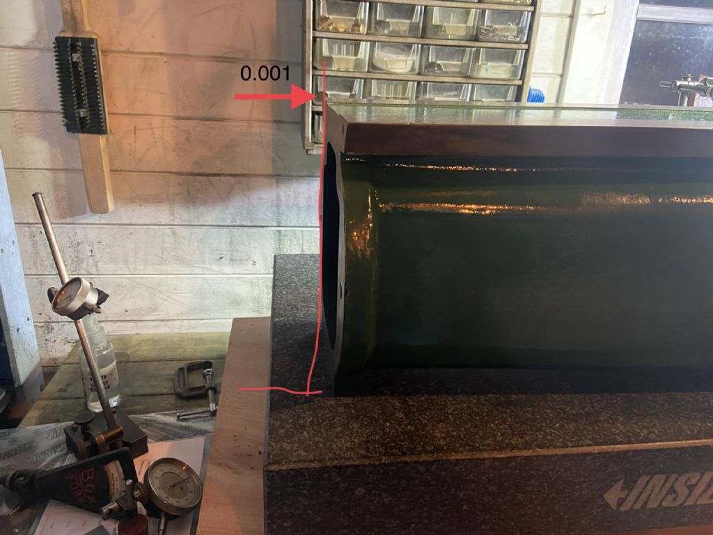
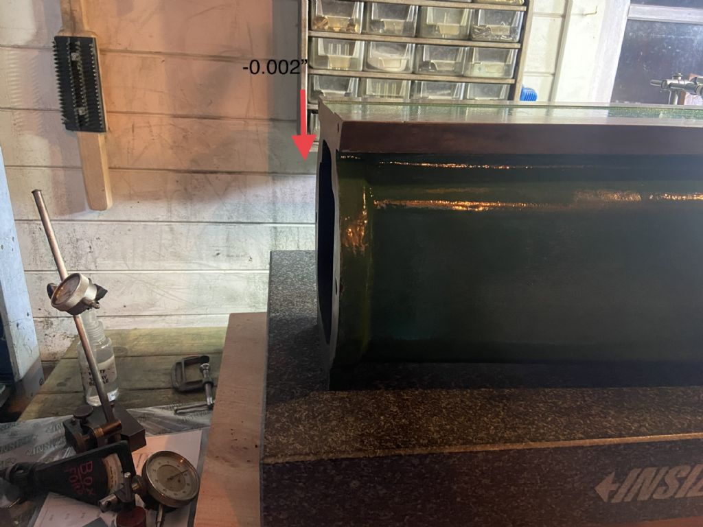
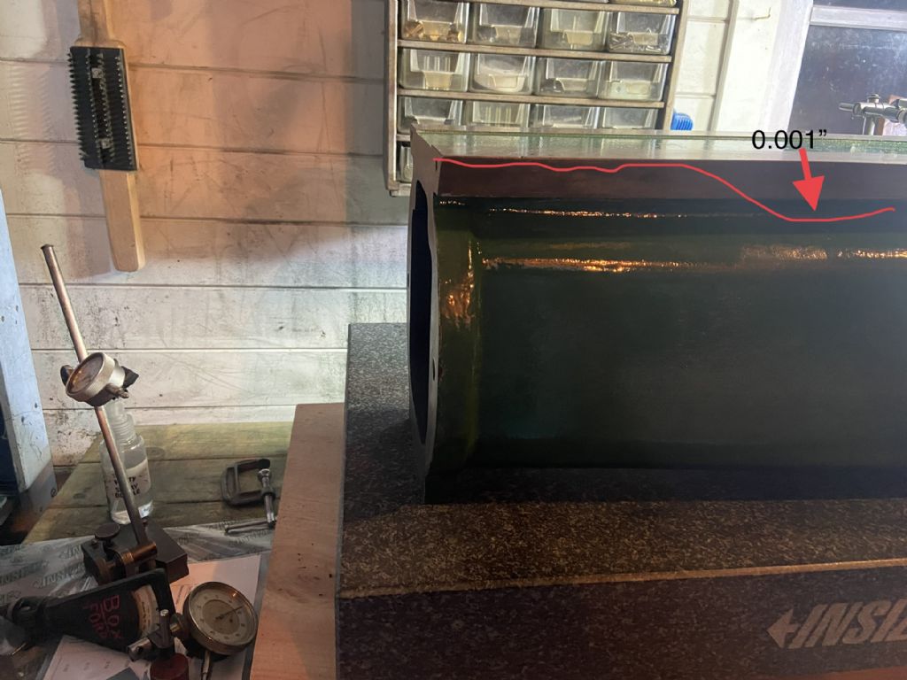
If you were to stand the column on the FRS and somehow measure the vertical 'tilt' of the front surface ways, you may then believe that you need to remove say 4 thou from one end of the ways. However, because the FRS is only about a quarter of the length of the ways, this translates to having to remove only 1 thou from one end the FRS – much easier! Also, the dovetails and front face ways, and their alignment to each other, should be pristine at either end of the column, and can act as references, so scraping 'tilt' out of the front face ways messes up the dovetails, more at one end than the other, making their re-alignment more difficult.
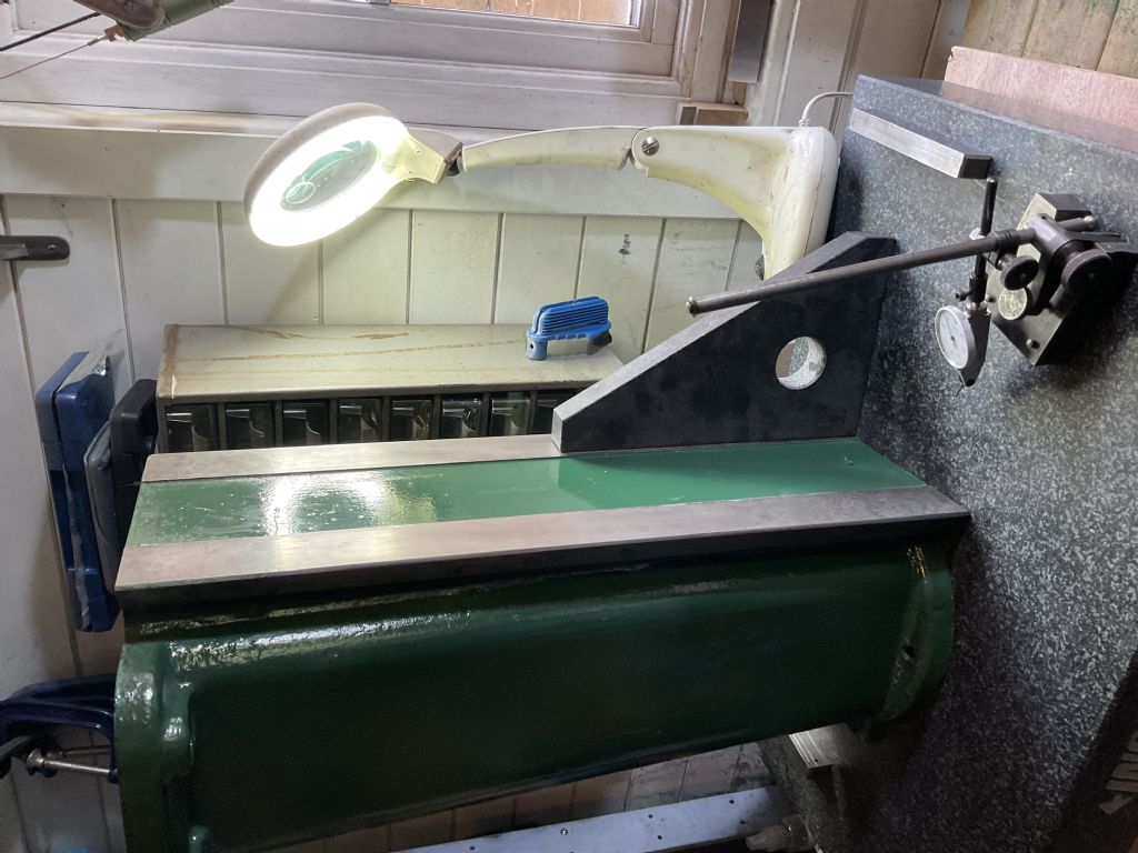
So, if you need to bring the worn front face ways flat, try to scrape a surface that effectively remains parallel to the plane passing through the unworn face at the ends of the column. Of course, you destroy this reference as soon as you scrape it, but that matters less than you might think. You can rest the column on the surface plate, on the lugs, if you believe they are – or have made them – reference surfaces, and measure the height of the front face. Or you could rest the column front face down, supported at either end, on parallels, and measure the gap twixt surface plate and face. But then, you have to be careful about keeping the places where the parallels will go parallel to each other. So measurement has its problems.
In fact, you can abandon measurement and just scrape the front face ways to the surface plate. You'll get a good idea of how it's going by the way the blue-marked areas move together (assuming the face is hollow). It's bad enough scraping the front face ways flat, without simultaneously having to worry about their relationship to the FRS all the time. No measurement…
Then, it's time to do the dovetails – always a challenge… That's my main reason for suggesting that the front face ways are worked first, with no real regard to the column ends – try to disrupt front face ways to dovetail surface alignment as little as possible.
Then, use this new, 'local'reference plane to adjust the base surface. That's easy for the 'front-to-back' right angle, but the 'sideways' alignment will require a gauge to be made that bears on the dovetail surfaces. (Sideways tilt doesn't matter so much at the spindle housing end, but, at the base, a Leaning Tower of Pisa looks bad…). When that's done, work the spindle housing end, ensuring the ends remain parallel (or at least the 'front-to-back' right angle). You'll need some sort of improvised gauge.. So, work from the most critical surfaces to the least critical.
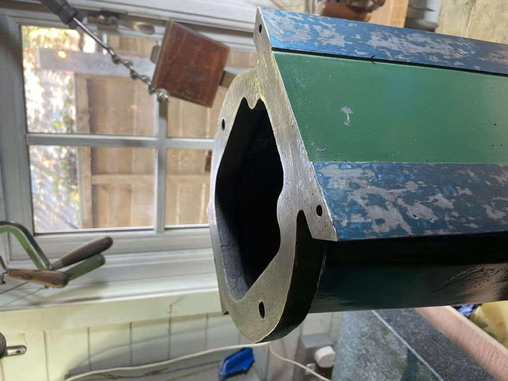
Incidentally, for bolting faces, as at the top and bottom of the column, there's no need to scrape for a high density of contact points, and the surface can be relieved in areas away from the bolt holes. Then, for correcting alignment, only small areas need to be scraped.
Hope that's clear and helpful. However, there's no 'right' way to do this, just a vast number of ways to make the job more difficult.
 peak4.

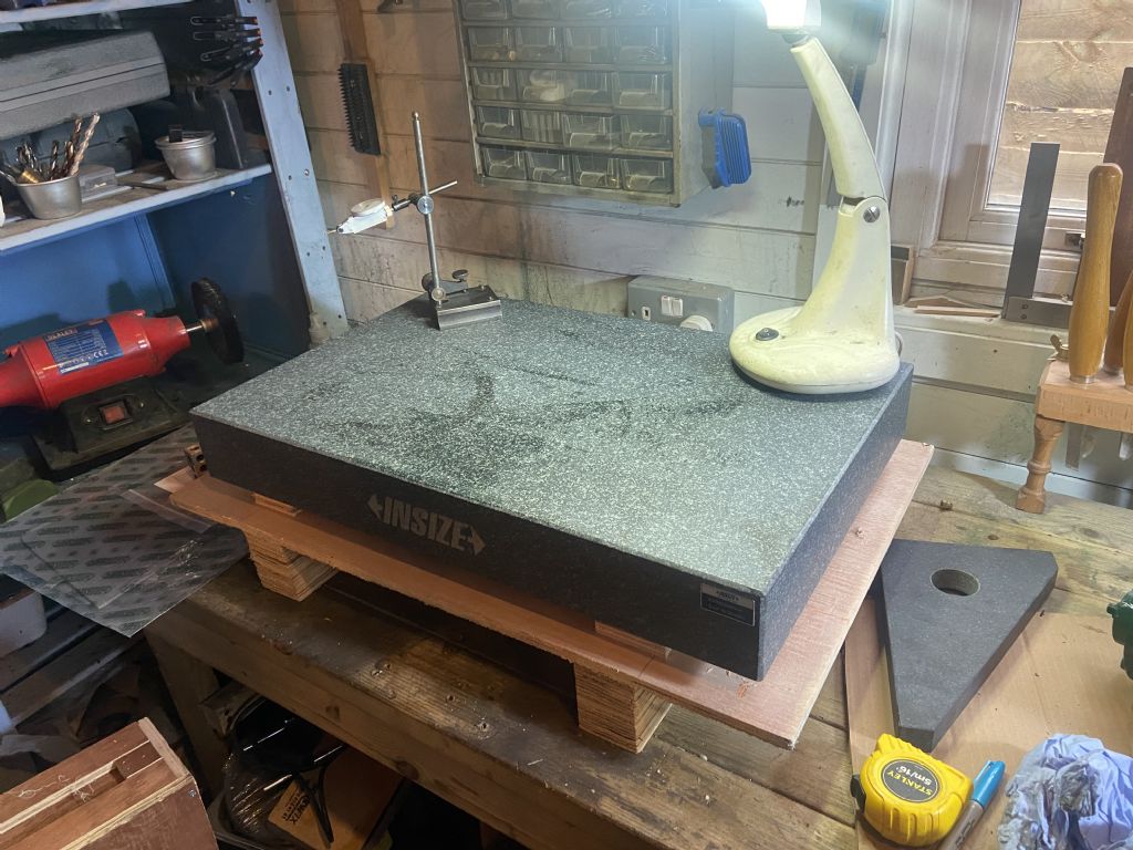
 and also it may be useful,to others attempting a similar project.