Surface finish when turning.

Advert

Surface finish when turning.

Home Forums Beginners questions Surface finish when turning.

Viewing 9 posts - 26 through 34 (of 34 total)
  • Author
    Posts
  • #552200
    Robin Graham
    Participant
      @robingraham42208

      Thanks for further replies.

      John (DMB) – I think I once made a tool similar to the one you describe (it made a shear cut and produced that feathery swarf), but I'd forgotten about it – happens all too often these days. Thanks for your suggestion.

      Diogenes – the OK finish on the already reduced diameter was largely due to Hermes, the God of wet 'n' dry. My lathe's gearbox doesn't allow the leadscrew and the power feed to be engaged simultaneously, so that's not the problem, but thank you for your input.

      Tony:

      "You are also only just 'skimming' the cold rolled bar stock. I have seen this effect on 3 phase lathes as well so not sure it's the motor?"

      Can you elaborate on that? Is that something to do do with a 'skin' on cold rolled stock? I'm not sure if it's germane to my problem – I saw the effect with deeper cuts, but posted the pic of a skim the hope of ruling out issues of lathe rigidity.

      Chris – twin smooth V belts. I have no idea how well the belts are matched though. I suppose if they're not well matched, it could be a cause of vibration. Thanks for pointing up that potential problem.

      John – the surface finish formula is interesting, but also (for me) frustrating – the author doesn't explain how he has arrived at it. There are are only three quantities in the formula – Ra number, feed rate and tip radius.. Presumably that means that other factors such as depth of cut and machine rigidity are negligible in his environment. Not so in mine! Maybe it's a CNC thing. I've no experience myself, but have seen the machines working and they seem to go for repetitive fast shallow cuts rather than hogging the metal off.

      Regards, Robin.

      Advert
      #552222
      Tony Pratt 1
      Participant
        @tonypratt1

        Robin, just saying I have seen that effect before & on 3 phase m/c's. If you get that effect on deeper cuts you can rule out the skin issue.

        Tony

        #552254
        Graham Meek
        Participant
          @grahammeek88282

          Going back to the original post. I would like to see a photograph of the toolpost set-up.

          My reason for asking is as follows.

          I have seen in the past where some folk in their pursuit to have interchangeable tooling, have gone for a unit which is far too big for the lathe in question.

          Such set-ups mean the main cutting forces on larger diameter work are not taken by the top surfaces of the bedways front and back, but by the front shear and the rear under-bed shear. The top rear bed surface taking no load at all. In this situation the carriage floats, which induces chatter. This effect would be reduced on smaller diameter work, ie 2.5" work as stated, because the geometry of the lathe tool is then working where the manufacturer intended.

          Generally,

          Light cuts and carbides do not usually go together, unless it is a tip specifically designed for it. I use Sumitomo T12A inserts which have a ground profile and a small tip radius. They work well on light cuts and leave an almost ground surface finish, especially on EN1A.

          Geared Headstocks struggle in the surface finish department. That is why most high end lathes use belt drives. My own Emco Maximat Super 11 which has ground tooth profiles on the headstock gears will produce the type of surface finish shown in the opening caption. Over the years I have learned how to overcome this. Nine times out of ten I go to a lower speed and it disappears.

          Regards

          Gray,


          Edited By Graham Meek on 02/07/2021 11:55:18

          #552327
          Robin Graham
          Participant
            @robingraham42208

            Tony – thanks,that clarifies your earlier comment.

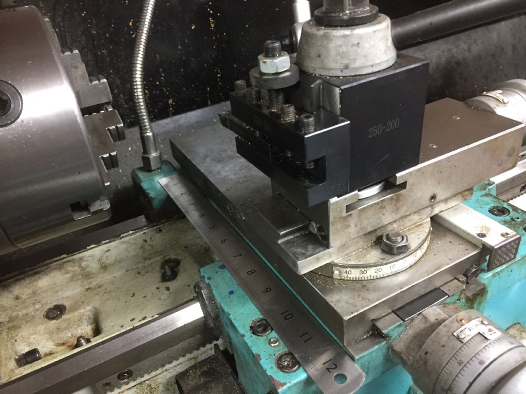
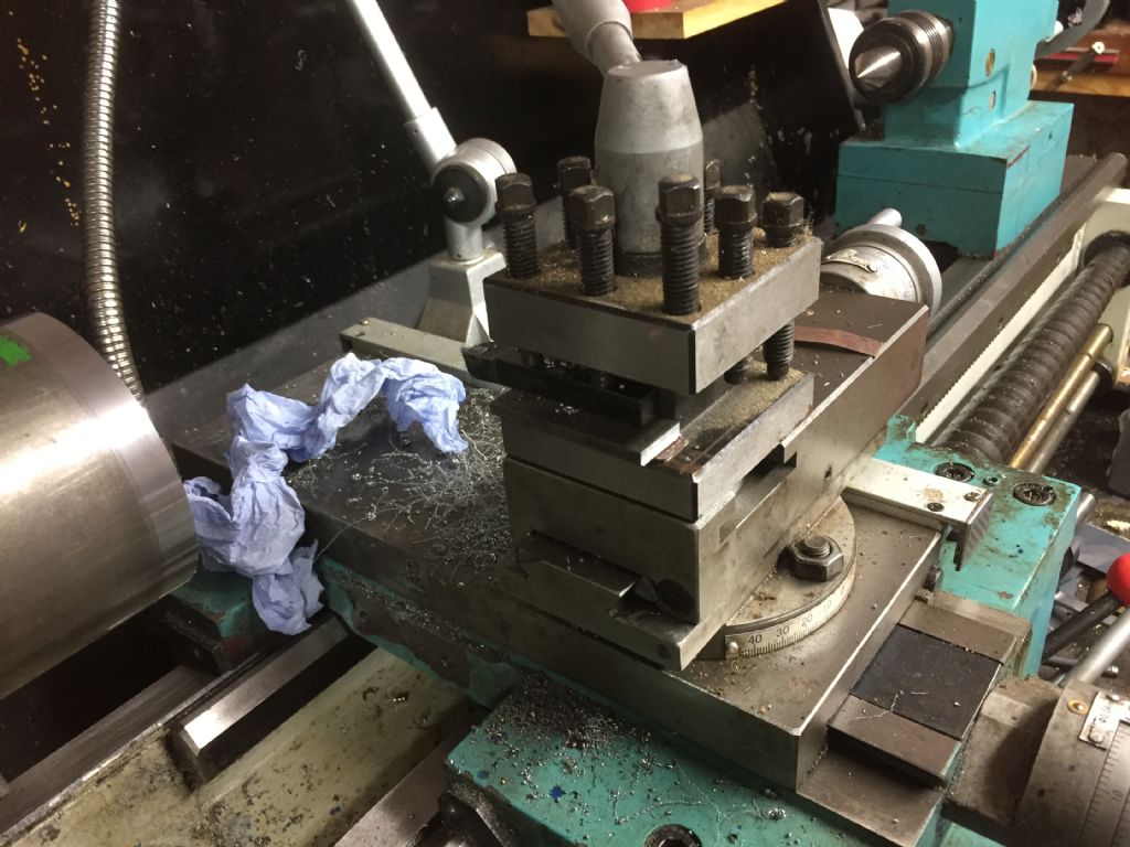
            Gray – thanks for your detailed reply. I was finding it very difficult to understand why the effect was more pronounced at larger diameters, but maybe you have explained it. Here is a photo of my QC tool post in a typical configuration:

            qctoolpost.jpg

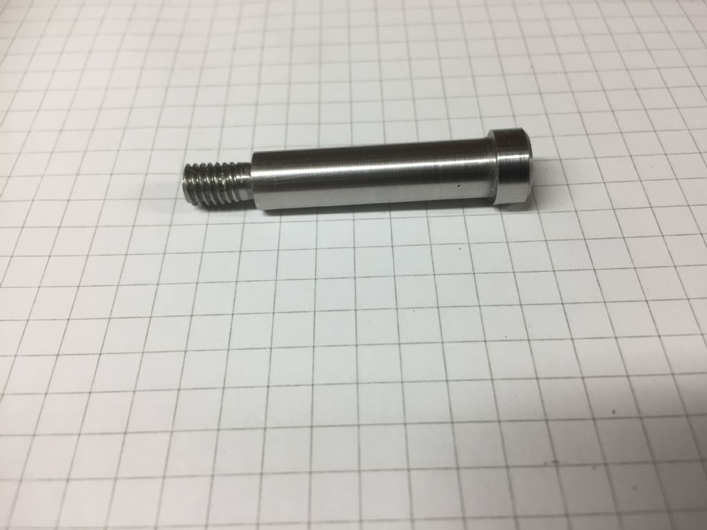
            Thanks also for you general comments. I have found that CCGT inserts (the ones I have are from ARC) are OK for finishing cuts in steel – this is an 8mm shoulder screw in silver steel I made tonight:

            shoulderscrew.jpg

            which was finished with a ~ 0.05mm cut. I'm happy with that sort of finish.

            I was interested in your comments about gear head machines as well – I had wondered if there was any point in converting the machine to 3-phase when there are other, perhaps more important, sources of 'noise' in the power train.

            Robin.

            #552351
            Howard Lewis
            Participant
              @howardlewis46836

              You appear to have solved the problem.

              Good!

              My Taiwanese lathe, (May be a close relative of what looks like an Axminster machine), has VFD, and surface finish is rarely a problem with a Tangential Turning Tool, or CCMT0604 inserts.

              It has to be said that I have halved the feed rate by making and fitting a 80T gear to replace the normal 40T input to the Norton box. This did involve relocating the closure for the gear cover.

              Howard

              #552381
              Graham Meek
              Participant
                @grahammeek88282

                Hi Robin,

                Glad to hear my few words have shed some light on the problem.

                From your photograph above the Main Body of your QC system is the full width of the topslide. A 4 tool Turret, (usually supplied these days) usually overhangs the width of the topslide by a small margin. On my Maximat it is about 2 mm.

                The Tool Holder length on your system sits outside the Main Block, and the cutting tool extends beyond the Tool Holder. From this, and because of all these projections, the topslide has to sit nearer the operator on larger work. Nearer than the Lathe manufacturer intended for that particular diameter of work when using the standard equipment.

                When working on smaller diameter work all the cutting forces are working between the bedways, where they should be.

                As a rough rule of thumb the tool holder length should be the same as the standard 4 tool Turret.

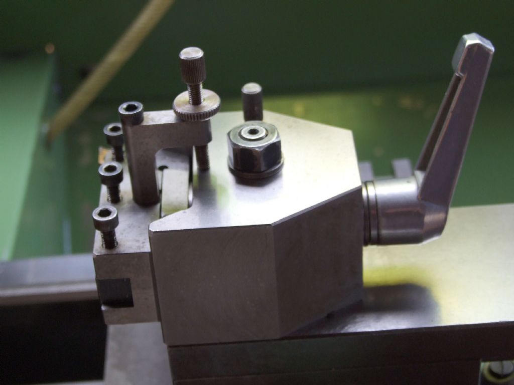
                fig 1 homemade interchangeable tooling.jpg

                Above is the Hardened & Ground Tool holding system I made for my Maximat back in the 1980's.

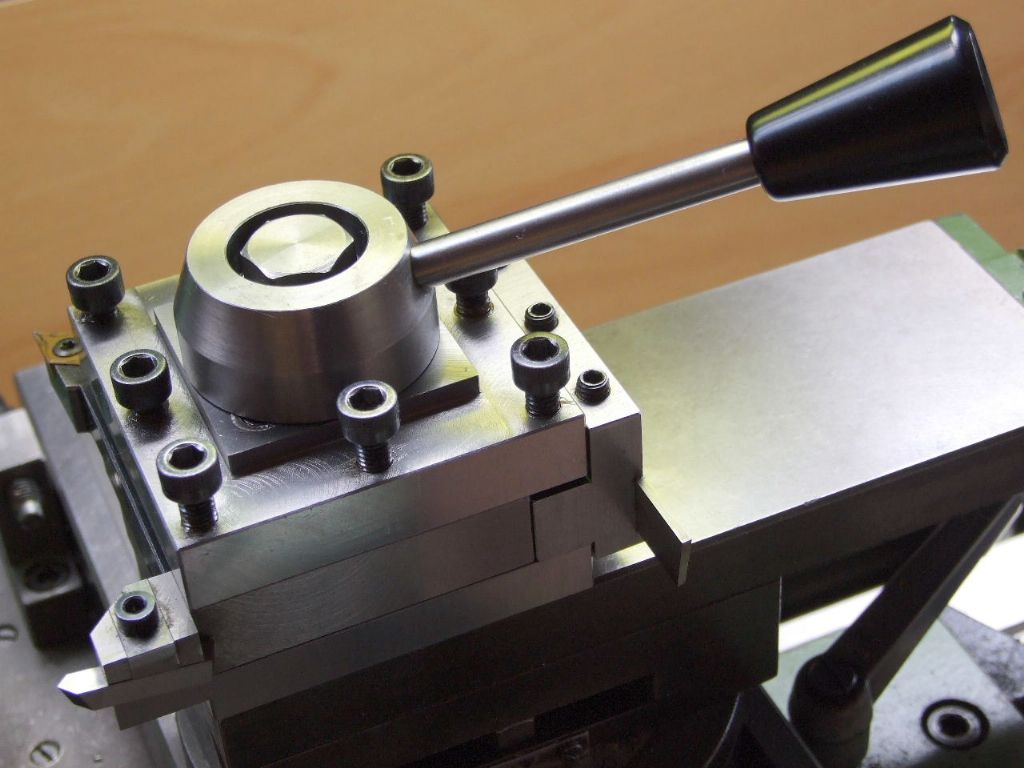
                Before I went over to the 4 tool Turret, (the Dark Side)

                fig 2 maximat 4 tool turret.jpg

                You will see the tool projection or overhang if anything is less with my QC system, as the length of the QC block is less than the width of the 4 tool Turret.

                Regards

                Gray,

                #552390
                Dave Halford
                Participant
                  @davehalford22513

                  Your tool is only held by two of the four clamp screws on the holder, that would cause trouble on my lathe.

                  #552498
                  soi keo blogfb88
                  Participant
                    @soikeoblogfb8835578

                    You are effectively cutting a screw thread by moving a cutting tool along rotating work at a constant rate.

                    #552636
                    Robin Graham
                    Participant
                      @robingraham42208

                      Thanks for further replies.

                      soi keo blogfb88 – thank you for taking the time to respond, and welcome to the forum. If you re-read my opening post you will see that I had already considered the possibility that I was cutting a screw thread before I posted, and rejected the hypothesis for reasons given in that post.

                      To wind this up (for me, for the present at least) I dug out the 4-way TP which came with the machine. When I bought the lathe (new) from Axminster it came with the QC mounted, and I just went along and used it without much thought.

                      I put the 4-way in place:

                      4-waytp.jpg

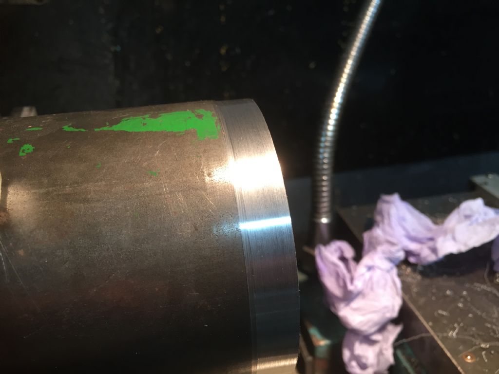
                      shimmed up a tool (PITA) and tried a cut under the same conditions as in my OP:

                      sf_with_4-way.jpg

                      OK, not wonderful, but no 'screw thread' or other weird patterns at different spindle speeds.

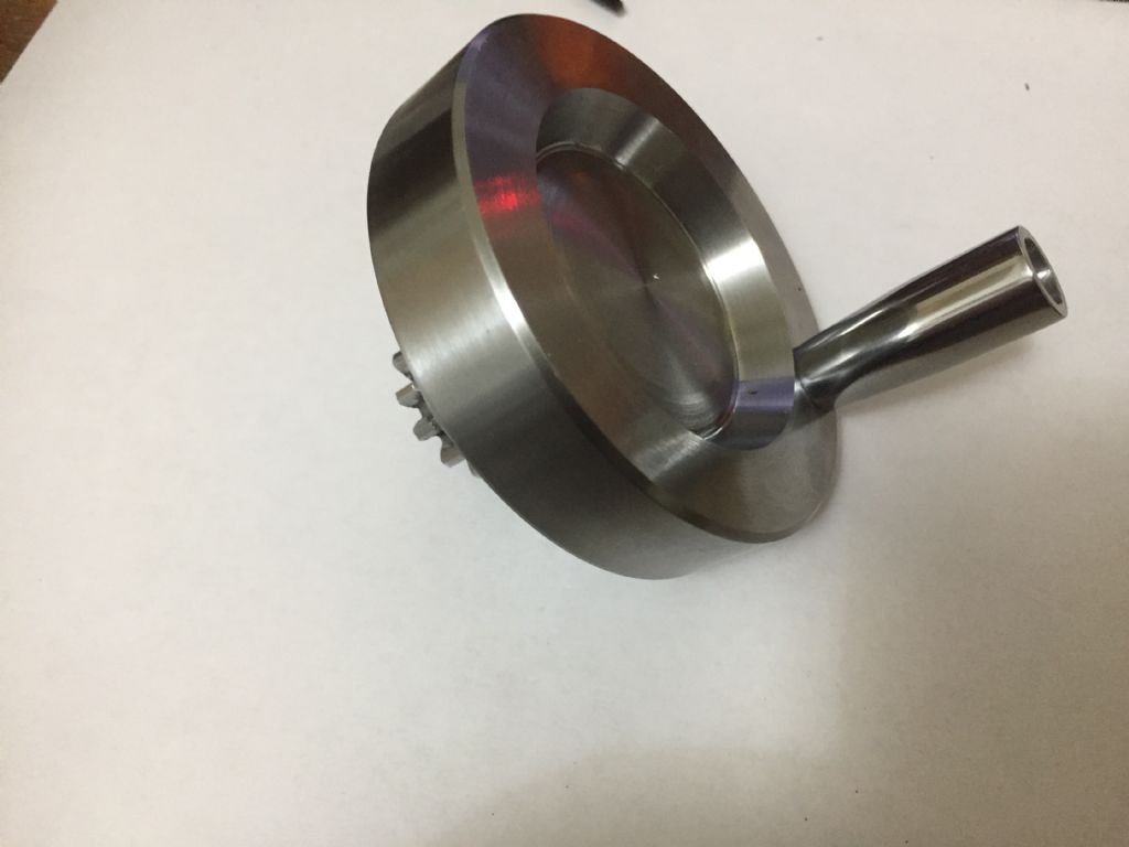
                      Eventually, after further experiments using the 4-way the part I was trying to make came out like this, straight off the lathe:

                      finishedhandwheel.jpg

                      Well, OK, I polished the winding handle, but the rest is as-turned. I'm pretty happy with that. Well, f*****g delighted actually.

                      Many thanks, and especially to Graham Meek who pointed me in a direction which wasn't on my compass, but seems to be the way to go..

                      Robin.


                      Edited By Robin Graham on 04/07/2021 23:10:21

                    Viewing 9 posts - 26 through 34 (of 34 total)
                    • Please log in to reply to this topic. Registering is free and easy using the links on the menu at the top of this page.

                    Advert

                    Latest Replies

                    Home Forums Beginners questions Topics

                    Viewing 25 topics - 1 through 25 (of 25 total)
                    Viewing 25 topics - 1 through 25 (of 25 total)

                    View full reply list.

                    Advert