Suggestions please.

Advert

Suggestions please.

Home Forums Hints And Tips for model engineers Suggestions please.

Viewing 25 posts - 26 through 50 (of 71 total)
  • Author
    Posts
  • #66310
    Sam Stones
    Participant
      @samstones42903
      Hi Graham,
       
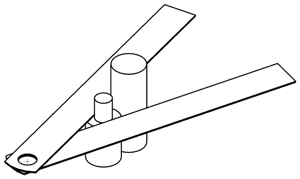
      Your `twin rule’ solution is a very neat idea, and puts more sense into my bit of geometry.
       
      I’m sure it will prove useful to others, especially if shown with a 3D picture.
       
      Thanks for your closing comment.
       
      Best regards,
       
      Sam
       
      Advert
      #66311
      alan frost
      Participant
        @alanfrost17805
        A simple solution ,but not too cheap is to buy the poor man’s projector , a magnifying loupe with the relevant graticule. get an illuminator a a few graticules and you can check all sorts of dimensions accurately.
        #66313
        The Merry Miller
        Participant
          @themerrymiller
          Another option I tried last night was to just take a pair of fixed joint “odd legs” or any other fixed joint calipers with straight backs.
           
          You then opened the legs fully such that the backs were almost in contact and then used those back edges for checking the angles.
          #66316
          mgj
          Participant
            @mgj

            I’d suggest you you enlarge to any convenient size on the wall using the shadowgraph technique. Make 3 spots on the wall with a fine point, measure sides carefully with say the points on digital calipers, and use the trigonometry wot is bilt into your calculator and which we were given as schoolboys. You will be accurate to several decimal places in less time than it takes to drink a cup of coffee, and be certain of the result., because any errors in measurement won’t at that size have much effect on the result, and in any case their effect will be reduced by the magnification factor.
             
            I know you trained as an engineer, so you won’t have to take your socks off to get an answer.
             
            #66317
            Sam Stones
            Participant
              @samstones42903
              Hi Graham,
               
              While you were fast asleep last night, I was hard at work cobbling out an interpretation of your smart method. Should anyone wonder what the blazes we were talking about in the distant future, they can view my renderings with jaw-dropping awe.
               
              If you are someone who has just tuned in, the steel rules are clamped together through their (already existing) holes.
               
              I must close for now, it’s almost lunch time here in Melbourne, and not a pot washed.
               
              Best regards to all,
               
              Sam

              Edited By Sam Stones on 31/03/2011 01:09:35

              #66320
              blowlamp
              Participant
                @blowlamp
                 
                Martin.
                #66334
                Ramon Wilson
                Participant
                  @ramonwilson3
                  Hi all, I’ve just had an email from Gray asking me to load this pic on his behalf.
                  He was trying to do so yesterday but was not able to do so for some reason
                   
                  I’m sure Gray will be on later to add more.
                   
                  Regards – Ramon
                   
                  #66339
                  Gray62
                  Participant
                    @gray62
                    Hi Graham,
                    I also have dificulties with visual acuity. ( Ihad a cornea graft about 6 years ago which improved this but still not perfect!)
                    As a result, I have great difficulty reading fine scales. I purchased a set of spectacle mounted loupes which give 2.5X magnification.
                    Whenever I do fine work, these are a fantastic aid to reading fine graduations and I find I can set almost any angle accurately.
                    Have a search on ebay, they are not too expensive and they greatly enhance our aging eyes
                    #66344
                    mgj
                    Participant
                      @mgj

                      Coalburner – like you my eyes are decaying too – I have a set of reading prescription specs with a x4 panel in the “bifocal” bit at hte bottom of hte lens. Work well. Opticians charged me for a pair of bifocals.

                      #66346
                      Terryd
                      Participant
                        @terryd72465
                        Hi Graham,
                         
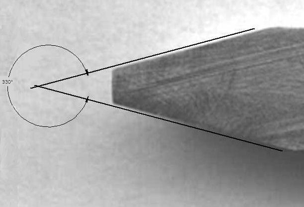
                        by adding lines to your scan after enlarging and importing into Deltacad I read the angle as 30 degrees. But I may not be accurate, have a look at the exported .jpg below any constructive comment would be gratefully accepted. Text is small but it reads ‘330 degrees’ i.e. 30 deg internal.
                         
                        Rgards
                         
                        Terry
                         

                        #66353
                        Tony Pratt 1
                        Participant
                          @tonypratt1
                          Graham, excellent ideas coming out of this posting! Very ingenious to use 2 rollers & 2 rules to get your angle, however I would stick to a sine bar and clock to check your tool it’s much more user friendly and from experience projectors can give spurious readings even the industrial ones made for the job.
                          Tony
                          #66360
                          Terryd
                          Participant
                            @terryd72465
                            Hi Graham,
                             
                            Send me a PM,.
                             
                            What browser are you using for posting. I think it is Google Chrome that has problems with pictures etc on this forum.
                             
                            Regards
                             
                            Terry
                            #66366
                            Steve Garnett
                            Participant
                              @stevegarnett62550
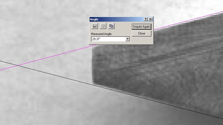
                              Graham, I loaded your jpeg into AutoSketch and blew it up so that I could see the jaggies along the edge and ran lines along them, which is as accurate as you can get with it, I think. Here is the result (only the end shown – the lines ran along the whole length):
                               

                              29.37 degrees.

                              Edited By Steve Garnett on 01/04/2011 11:26:38

                              #66373
                              MichaelR
                              Participant
                                @michaelr
                                Using a “Line of Cords” rule may be the way.
                                 
                                Stick

                                Edited By Stick on 01/04/2011 13:48:28

                                #66387
                                Sam Stones
                                Participant
                                  @samstones42903
                                  Hi Graham,
                                   
                                  Thanks for alloting me some credit wrt my `jig’. It’s very flattering.
                                   
                                  Here’s another clue about what seems to be happening (with respect to the efforts of others).

                                  Isn’t there a risk that the posted photograph of the tool bit is very slightly skewed away from the camera? Even if the camera is near perfect, the top face of the tool bit must be perpendicular to the lens axis. 
                                   
                                  Any tilt front to back, will increase the `optically’ measured angle, and therefore why it is that using the photograph (and CAD), is showing values greater than 29 degrees.
                                   
                                  Of course, any sideways tilt will reduce the CAD-determined reading.
                                   
                                  Regards to all,
                                   
                                  Sam

                                  Edited By Sam Stones on 01/04/2011 21:44:32

                                  #66388
                                  Steve Garnett
                                  Participant
                                    @stevegarnett62550
                                    Posted by Sam Stones on 01/04/2011 21:23:36:

                                    Isn’t there a risk that the posted photograph of the tool bit is very slightly skewed away from the camera? Even if the camera is near perfect, the top face of the tool bit must be perpendicular to the lens axis.
                                     
                                    Any tilt front to back, will increase the `optically’ measured angle, and therefore why it is that using the photograph (and CAD), is showing values greater than 29 degrees.
                                     

                                    I wondered about that when I did the measurement, I must admit. If you look at the other end of the tool, certainly it looks as though the upper side is aligned pretty well, but if that’s true, and this is on the lens axis, then the lower end has to have a slight error, as you point out. This is one of the reasons that Ramon’s idea of using the scanner is almost certainly the best option – no fixed axis point for a lens, so if the angle you want to measure is on the glass bed, then that’s exactly what you get – just that angle (within the scanner limitations, of course).

                                    #66389
                                    Les Jones 1
                                    Participant
                                      @lesjones1
                                      Hi Steve,
                                      The point you have just made (Which I had not thought of.) is another reason not to use a USB microscope as it will be very close to the object being measured thus increasing the error. If a camera must be used then it would be best to use it with the longest focal length setting. (Telephoto mode.) to minimise the errors.
                                       
                                      Les.
                                      #66394
                                      mgj
                                      Participant
                                        @mgj
                                        Errors in scanning and photos/printing. I had a think about this one because it worried me slightly – things didn’t gell, and there was a gap in the logic.
                                         
                                        If you simply scan an image, and then print it, you get a like for like transfromation of the pixels. The aspect ratio doesn’t alter. If there was distortion then it would show in the finished print.It would look odd. So the process is, of itself a simple translation and is inherently accurate. (Lets not get involved in the finer detail of digital capture). We know that must be true if the picture is printed 1:1 at say 300 DPI. You are using all your pixels, and each pixel has a position as part of its definition and its size is fixed by the magnification
                                         
                                        So where can errors come in.
                                         
                                        The common one is that the screen resolution is incorrectly set, so aspect ratio is altered. However that won’t affect the print – unless one does something to the print on screen to alter an error, and the printer will do what it’s told to do and give a “false” distortion. So unless oyu are sure your screen is distortion free and properly set you can’t trust it (unless you have ahigh end photo screen and if one does, you don’t need to be bothering with this!)
                                         
                                        The next possibilty is in the scanner. Scanners are generally designed to scan flat objects. The distance fom scanner head to object is usually very short so any error in placing/parallelism of the object represents a large % of distance and hence quite a lot of distortion can, not necessarily will of course, creep in. But , as has been suggested, if you can get the object flat (or the bit of it that one is interested in) then it will be distortion free, so long as the scanner drive belt is is good nick and hasn’t stretched.
                                         
                                        You are actually better off taking a photo, especially if you have a close focussing lens. BUT, the back of the camera has to be parallel to the plane, in both axes, or distortion WILL be introduced. (Though it is easy enough to take out in a proper photo editing suite that has a perspective/warp command, and some sort of straight edge truly at the vertical is included in the pic).)
                                         
                                        You can get errors in the lens, but in general they will be small, and largely disappear if the lens is stopped down, and the object pretty central in the frame.
                                         
                                        So on reflection I reckon the easiest way to get this angle is to take a (macro) photo, set the camera and object up properly with spirit levels as is normal practise for this kind of thing, enlarge as much as possible, and then use trig. Done properly thats the least errors for most magnification.


                                        Edited By mgj on 02/04/2011 00:35:21

                                        #66395
                                        Steve Garnett
                                        Participant
                                          @stevegarnett62550
                                          Oh, the murky world of scanning… Graham, don’t worry about the monitor – it will have a much greater resolution than the scanner does anyway, when you’ve zoomed right in to your image and are looking at those blocky pixels…
                                           
                                          But I said murky, and I meant it. With a scanner, the so-called ‘resolution’ obtained, when it is a very high pixel number, isn’t really the resolution of the scanner at all – it’s a number derived by interpolation. What this means is that all images are scanned at the scanner’s native optical resolution, and to make this seem greater, the in-between values are established from the values either side, and pixels resulting from this are included in the output. What this means in terms of measurement though, is that as long as you make sure you scan at at least the optical resolution of the scanner, that’s actually as good as it’s going to get, regardless of whether you set a higher pixel rate.
                                           
                                          And with most modern scanners, that’s pretty good. But with all scanners, it means that when you zoom right in, ultimately you don’t get a straight line but a series of pixel steps. That’s fine though, as they are pretty accurate steps! And if I run a vector line in CAD carefully along the top of them, and another one along the lower ones and measure the angle between them, it is going to be as good as you can get. And, as I indicated, you don’t get lens-based distortion. Normally taking a picture in this way of a 3D object would be pretty bad – it would distort it – but when it comes to an accurate measurement on the scanner plane, it’s exactly what you want. Also (perhaps controversially) it’s going to be easier to achieve a good result like this than it would be with a shadowgraph, because to get a good shadowgraph result the same issue occurs with the light source; you have to make damn sure that it’s positioned midway between the angle you want to measure and aligned parallel to the display, or you still run into the problem that Sam identified.
                                           
                                          As long as you use it with care, I don’t see any way to make a better measurement without spending an absolute fortune on some optical refractometry and a fringe-counter, and for these sorts of measurement that’s going to be a bit of a bugger to set up.
                                          #66397
                                          Terryd
                                          Participant
                                            @terryd72465
                                            Hi Graham,
                                             
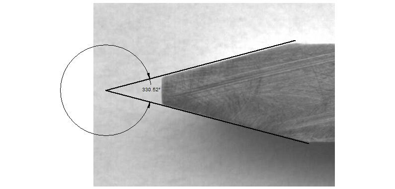
                                            I agree with Steve quite closely and make your angle about 29.48 deg
                                             

                                            Is that close enough?
                                             
                                            I imported you jpg from PS Pro into Deltacad after cropping and then added the angular dimension. I checked the accuracy by printing from each application and measuring and the result was the same in both cases i.e. both printouts matched.
                                             
                                            Best regards
                                            Terry
                                            #66399
                                            mgj
                                            Participant
                                              @mgj
                                              Resolution is a funny hting.
                                               
                                              Most screens are set to a resolution of 70-90 dpi. (tehy can do better of course, but that will give you photographic quality) Most scanners are scanning at a lot higher than that . Yes you can get interpolation at some resolutions with scanners, but only at the highest resolutions usually, and frequently only in one plane.
                                               
                                              “Jaggies” are called aliasing and are a function of digital capture. The thing is that, that to a digital interface, a pixel does not exist. Its just a wedge of data about luminosity and colour and mathematical coordinates regarding position. Its shown as a square on a screen because the screen has to find a way of presenting a point. On the scanner/camera the photosite can be any shape. Some are round, some are square I think (or were) and some are hexagonal. (My camera ones are hexagonal for several very good reasons, but they show as squares. ) Also interpolation doesn’t affect aspect ratio so it doesn’t lead to distortion. Its a gap filling exercise between known points – withn reason.
                                               
                                              We are generaly pushing the liits. If you set up your camera/shadowgraph or scanner with reasonable accuracy and follow the principles, you are going to get a pretty decent result. In the case of this exercise where we need a gear cutter, sensible precautions and a bit of magnification ill produce a cutter or measureent htereof which is far more accurate than is usable. If also this small error is constant and appears on every tooth then is won’t have an effect anyway other than to incraese or decrease stress levels withing the tooth by some tiny amount.Its not going to affect the drive in any meaningful way..
                                               
                                               
                                              Better to be approximately right than exactly wrong?
                                              #66400
                                              Ian S C
                                              Participant
                                                @iansc
                                                At one stage I contemplated obtaining an old overhead projector, with the object of using it as an optical comparitor. Another machine that might have posibilities is a micrfish reader, both these machines are becoming obsolete, but my source of supply has fallen over(literally). I can’t remember whether it was in ME or MEW but a good few years back there were plans for an optical comparitor. Ian S C
                                                #66402
                                                Steve Garnett
                                                Participant
                                                  @stevegarnett62550
                                                  Oh come on, guys. Go out and take a picture of a tall vertical building with a camera and see what happens to the verticals. Can you find a place where they come out parallel? Even the best lenses produce spherical aberrations, and only represent a view from a fixed point. So if you introduce a lens into a system intended to make an angular measurement, it will come out wrong. The huge advantage of the scanner is that it is using a linear grid-based method of acquiring the image (in just the same way that your digital camera does) without introducing a lens, and inevitable distortion. As for overhead projectors – well they all come with an adjustment called ‘keystone correction’, and this is an attempt to correct for exactly the same thing, in the vertical direction.
                                                   
                                                  I only referred to ‘jaggies’, because people can identify with the term easily. The word ‘pixel’ is a contraction of ‘Picture Cell’, and these represent the individual output of each sensor on the CCD device, so yes, they exist. The output of each cell is clocked out of the sensor, and digitised – how can they not exist? You wouldn’t get pictures at all if they didn’t!
                                                   
                                                  Anyway, if you want to use an optical system, or a single-point shadowgraph, you have to calibrate the whole system to minimise errors, at the very least. Using a modern scanner to all intents and purposes eliminates this major source of error completely, and is likely to give you a damn sight more accurate result.
                                                  #66403
                                                  Nicholas Farr
                                                  Participant
                                                    @nicholasfarr14254
                                                    Hi, with this question of distortions while scanning, you may be able to scan you rulers set by your two rollers, to the same settings that you have scanned your cutter at, you could then print this off on to a piece of overhead projector film and overlay it onto the print out of your cutter. Any distortions should be the same in both print outs. Of course you will have to be able to have two rulers or whatever else you may be able to use, that will lay flat on the scanner. This may be achieved by carefully cutting a suitable piece of card or the like to your ruler settings with a knife.

                                                     
                                                    Just a thought.
                                                     
                                                    Regards Nick.
                                                    #66404
                                                    Steve Garnett
                                                    Participant
                                                      @stevegarnett62550

                                                      Nick, have you looked at page one of this thread? That’s pretty much where I started from!

                                                    Viewing 25 posts - 26 through 50 (of 71 total)
                                                    • Please log in to reply to this topic. Registering is free and easy using the links on the menu at the top of this page.

                                                    Advert

                                                    Latest Replies

                                                    Viewing 25 topics - 1 through 25 (of 25 total)
                                                    Viewing 25 topics - 1 through 25 (of 25 total)

                                                    View full reply list.

                                                    Advert

                                                    Newsletter Sign-up