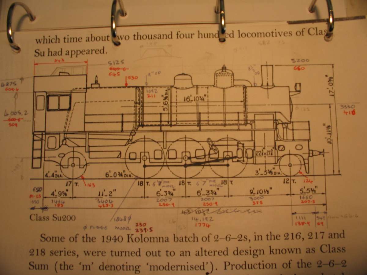
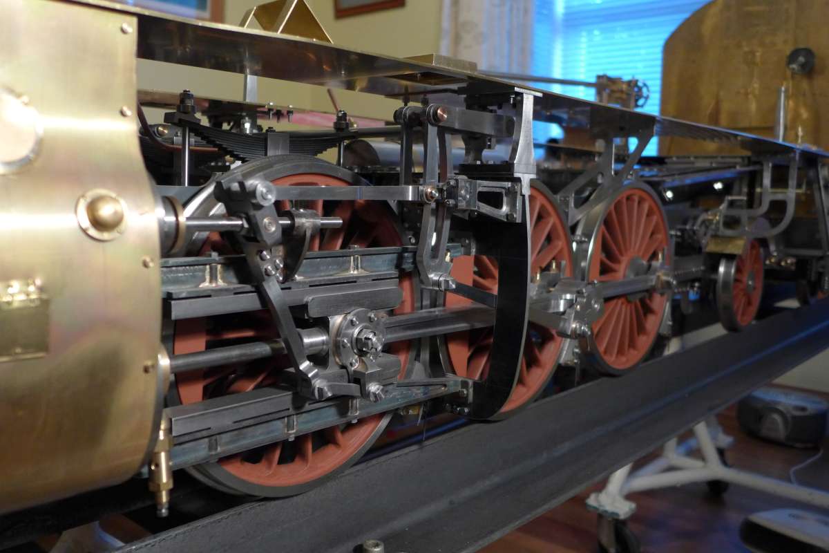
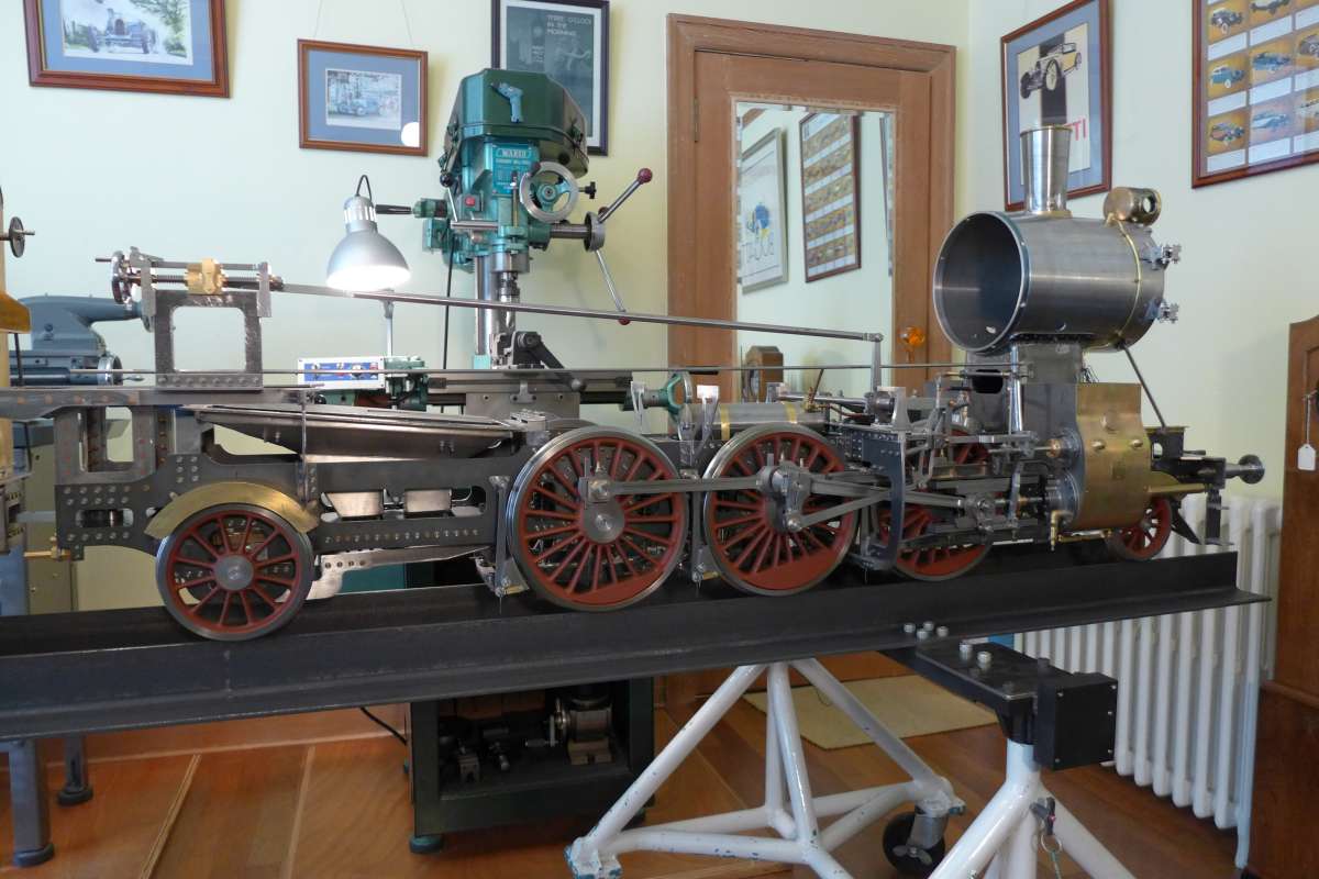
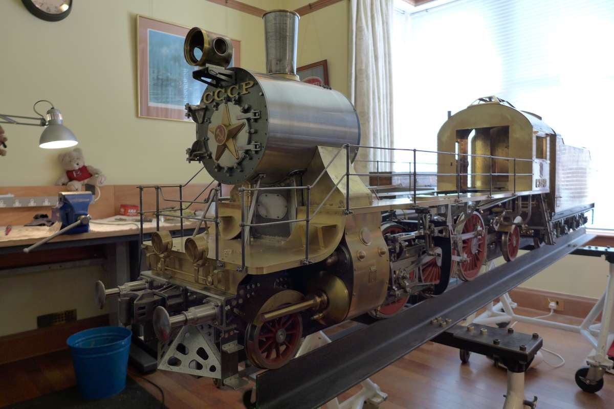
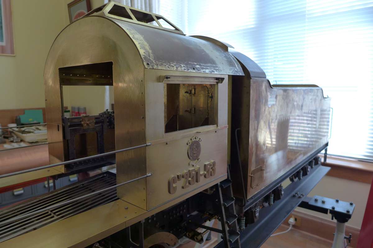
Su251-53
Su251-53
- This topic has 19 replies, 10 voices, and was last updated 3 April 2025 at 10:16 by
 parovoz.
- Please log in to reply to this topic. Registering is free and easy using the links on the menu at the top of this page.
Latest Replies
-
- Topic
- Voices
- Last Post
-
-
Pragotron Slave Clock
Started by:
renardiere7
in: Clocks and Scientific Instruments
- 6
-
6 July 2025 at 16:37
renardiere7
-
Twin Engineering’s heavy mill/drill quill removal
1
2
Started by:
Martin of Wick
in: Manual machine tools
- 11
-
6 July 2025 at 15:46
Pete
-
New member
Started by:
nige1
in: Introduce Yourself – New members start here!
- 3
-
6 July 2025 at 15:14
nige1
-
Starrett and other tool manufacturer wood boxes
Started by:
Ian Owen NZ
in: Workshop Tools and Tooling
- 11
-
6 July 2025 at 15:09
Clive Foster
-
M type top slide conversion??
Started by:
jimmyjaffa
in: Beginners questions
- 7
-
6 July 2025 at 14:20
David George 1
-
Boiler Design – issue 4765
1
2
…
7
8
Started by:
Charles Lamont
in: Model Engineer & Workshop
- 26
-
6 July 2025 at 13:05
lezsmith
-
Colchester Chipmaster Clutch question
Started by:
Peter_H
in: Manual machine tools
- 4
-
6 July 2025 at 10:47
Peter_H
-
Sanjay’s Banjo Engine
Started by:
JasonB
in: Stationary engines
- 3
-
6 July 2025 at 09:58
JasonB
-
In memoriam: Peter Neal
Started by:
jamesn
in: The Tea Room
- 1
-
6 July 2025 at 09:53
jamesn
-
Wickseed power hacksaw 8” information
Started by:
simonkeeligan@me.com
in: Beginners questions
- 2
-
6 July 2025 at 07:44
Nicholas Farr
-
Bentley BR2 Rotary Aero Engine
Started by:
notlobgp14
in: Miscellaneous models
- 4
-
5 July 2025 at 22:46
notlobgp14
-
Starrett micrometer.
Started by:
Graeme Seed
in: Workshop Tools and Tooling
- 7
-
5 July 2025 at 21:30
peak4
-
Dial test indicator vs Dial indicator
Started by:
martian
in: Workshop Tools and Tooling
- 17
-
5 July 2025 at 20:19
martian
-
Speed camera
1
2
3
Started by:
David George 1
in: The Tea Room
- 23
-
5 July 2025 at 19:40
John Haine
-
Any ideas how to repair this?
Started by:
Ian Parkin
in: Related Hobbies including Vehicle Restoration
- 11
-
5 July 2025 at 15:36
Pete Rimmer
-
Chucking Money Away!
Started by:
Chris Crew
in: The Tea Room
- 6
-
5 July 2025 at 12:55
Chris Crew
-
2 Machine lights
Started by:
modeng2000
in: Workshop Tools and Tooling
- 2
-
5 July 2025 at 11:58
Dalboy
-
Boxford lathe & vertical mill VFD conversion help with start stop
Started by:
Andrew Schofield
in: Beginners questions
- 8
-
5 July 2025 at 11:39
Clive Brown 1
-
1965 Colchester Chipmaster
Started by:
andyplant
in: Introduce Yourself – New members start here!
- 6
-
5 July 2025 at 11:09
Rod Renshaw
-
What Did You Do Today 2025
1
2
…
6
7
Started by:
JasonB
in: The Tea Room
- 33
-
5 July 2025 at 09:26
Nick Wheeler
-
Amadeal AMABL210E Review – Any Requests?
1
2
Started by:
JasonB
in: Model Engineer & Workshop
- 16
-
5 July 2025 at 05:49
Diogenes
-
ML10 backgear
Started by:
alexander1
in: Manual machine tools
- 3
-
5 July 2025 at 00:11
Bazyle
-
The Perpetual Demise of the Model engineer
Started by:
Luker
in: Model engineering club news
- 13
-
4 July 2025 at 17:06
JasonB
-
Advice moving 3x machines
Started by:
choochoo_baloo
in: Workshop Techniques
- 5
-
4 July 2025 at 15:46
Bazyle
-
Black plastic to replicate Bakelite
Started by:
Craig Brown
in: Materials
- 8
-
4 July 2025 at 15:35
nj111
-
Pragotron Slave Clock
Latest Issue

Newsletter Sign-up
Latest Replies
- Pragotron Slave Clock
- Twin Engineering’s heavy mill/drill quill removal
- New member
- Starrett and other tool manufacturer wood boxes
- M type top slide conversion??
- Boiler Design – issue 4765
- Colchester Chipmaster Clutch question
- Sanjay’s Banjo Engine
- In memoriam: Peter Neal
- Wickseed power hacksaw 8” information

