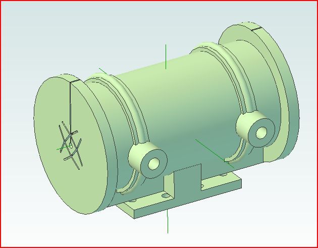
Stuart Victoria cylinder

Advert

Stuart Victoria cylinder

Home Forums Workshop Techniques Stuart Victoria cylinder

Viewing 11 posts - 1 through 11 (of 11 total)
  • Author
    Posts
  • #15942
    Andy Freeman 1
    Participant
      @andyfreeman1

      How to bore the cylinder?

      Advert
      #297367
      Andy Freeman 1
      Participant
        @andyfreeman1

        I am machining my first steam engine, a Stuart Victoria.

        The first cylinder I bored out I made a right dogs dinner of it! I used a mandril through the rough casting bore to position it central in a 4 jaw chuck. Anyway that resulted in a way off centre bore.

        Now I am on cylinder # 2. Looking at various videos and photos of how other people have done this, it seems the first operation is to machine the valve chest surface flat. I have done this and now have it on an angle plate on the face plate.

        The thing I am struggling with now is how the get the cylinder 'all lined up'. I can not really clock the outside diameter of the cylinder as it is not completely round. If I clock on the inside of the rough bore, that might be true on the outside face but the cylinder may not be aligned squarely along its axis. At least that's what I think. Maybe I am wrong?

        I have passed a 15mm dia bar through the lathe spindle and out through the cylinder to see if I can roughly eye it up as shown in the photo. This may look central on the outside face but maybe the inside face (against the face plate) is not centrerd?

        Its a bit of a difficult thing to explain but maybe someone understand what I mean and can point me in the right direction.

        Thanks

        cylinder holding small.jpg

        #297372
        Simon Collier
        Participant
          @simoncollier74340

          Andy, there a a few ways you can do this. First determine how much metal you have to play with, i.e., how much machining allowance is there on the casting? It looks pretty nice from the picture so I am guessing the bore is fairly parallel. Use a vernier to measure bore to port face, and bore to drain cock land, on each end of the cylinder. This will tell you how close to parallel the bore is to your machined port face. If the edges of the port face are to be machined, machine them square and parallel to the port face. Then clamp with these edges square to the face plate, face the cylinder end and bore. There must be plenty of step by step photo essays of this on the net for similar cylinders.

          #297399
          JasonB
          Moderator
            @jasonb

            Usual way is to plug th ends with a bit of hardwood and file flush to the cylinder ends. Use odd leg callipers or something similar to strike a series of arcs from the edge of the flange, if you do say 4 arcs you will most likely end up with a small square or rectangle scribed onto the wooden plug. It is then far easier to eyeball the centre of this square and put in a punch mark.

            Blue the ends and area around the drain cock bosses. Then with the cylinder port face on a flat surface use a square to scribe lines vertically up from your ctr mark and joint them with a line across the cock bosses.

            You can now mount it as you show on teh angle plate and get the punch mark to run true while also holding a square on the faceplate to check your scribed line runs at right angles which will put your casting on teh lathes axis.

            cylinder layout.jpg


            J

            Edited By JasonB on 10/05/2017 09:26:13

            #297406
            Anonymous

              I'd be inclined to use a thicker clamp bar. The one shown will just bend rather than clamp.

              Andrew

              #297415
              Martin Kyte
              Participant
                @martinkyte99762

                I agree with Jason (and Andrew). Bung up the bore with wooden plugs so you get a surface to mark the centres. Put your centres in by you own preferred meathod, odd legs, circular template etc. Now stick the thing on a surface plate and check your reference face against the centres as Jason has suggested. You may well have to file the port face/ steamchest flat so the centres sit at the same hight. Do as much as you can on the surface plate first to satisfy yourself that everything is as you would wish.

                I have to confess to being impatiant with this preparation stage and I always regret not taking more time over it. I really does pay dividends later. Castings are awkward compared to stock material, you have to create your own reference faces. I am getting better at it.

                regards Martin

                #297417
                Nigel McBurney 1
                Participant
                  @nigelmcburney1

                  Agree thicker clamp required,possibly wider so that it grips on the drain cock bosses,this area of the casting is stiffer and not so likely to distort the casting ,if the casting distorts under too much pressure then the machined cylinder bore may end up oval,after roughing the bore check that the casting has not moved due to the intermittent cutting of the boring tool on the rough cast surface.

                  #297428
                  mechman48
                  Participant
                    @mechman48

                    Agree that a thicker clamp is needed; possibly one from the clamping kits used for milling machines if you have a set, will also help to offset the imbalance that the angle plate will create as it spins so you would probable need some form of weight fixing opposite the angle plate.

                    George.

                    #297430
                    Ian S C
                    Participant
                      @iansc

                      The clamp bars I make are 8 mm/10 mm x 20 mm strips on edge with a 10 mm + gap to take the 10 mm studs from my clamping set for my mill.

                      Ian S C

                      #297457
                      Raymond Griffin
                      Participant
                        @raymondgriffin40985

                        My article “Boring castings”, published in Model Engineer Vol 217, No. 4538, 8-21 July 2016 could be helpful. I can send a copy by e-mail if required. Your setup looks flimsy for the task. Think about buying a Keats angle plate; they are cheap and effective. Mine came from Kirjeng. If angle plate not on, beef up your retaining bar strap, preferably for one with a V shape. The bar through the hole in the casting will not work as cast holes are rough and rarely central. The photo here shows a Stuart steam hammer casting; similar to the Victoria I have made the double Victoria, so understand the problem.

                        photo 11.jpg

                        #297462
                        JasonB
                        Moderator
                          @jasonb

                          As you have already machined the port face your angle plate is best, a keats plate will not make it easy to set the machined face at right angles to the faceplate, would have been OK if boring and facing one end was the first op.

                          A bit of angle can also be used as a clamping plate if you have something laying about and a few change gears make good counter balance weights. This one is a bit larger, 10" faceplate for scale.

                        Viewing 11 posts - 1 through 11 (of 11 total)
                        • Please log in to reply to this topic. Registering is free and easy using the links on the menu at the top of this page.

                        Advert

                        Latest Replies

                        Home Forums Workshop Techniques Topics

                        Viewing 25 topics - 1 through 25 (of 25 total)
                        Viewing 25 topics - 1 through 25 (of 25 total)

                        View full reply list.

                        Advert

                        Newsletter Sign-up