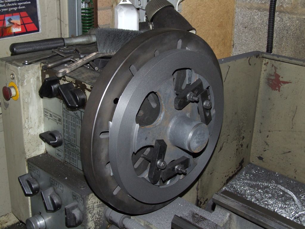
You are not alone. I noticed that parting had become a bit noisy today – then discovered that I could move the cross slide sideways about 0..5mm! Not sure how I managed to part 2" a week ago…?
Measure up carefully, you may well be able to rescue your cylinder. Keep it anyway, as one day you will make a steam engine to your own design, and then you can use it.
There's a thing called a 'Keats Angle Plate' that makes mounting cylinders on faceplates a doddle (wish I had one). Even without one, an ordinary small angle plate plat can be a big help – mount the cylinder with the port face against the block.
Make sure the boring tool can go right through the cylinder without damaging teh faceplate.
A big thanks for that, it looks like just what I need to make things a bit easier with the cylinder but useful for other things too by what I've read – I'm going to get one…
No problems so far, need to drill and fit the grubscrew next.. It was a bit awkward not having suitable packing and I was a bit worried of overtightening – but I've managed (I've not accumulated much in the way of offcuts etc yet…)…
The Flywheel faced and bored the 1st side.
Setting up to do the reverse side.
The Flywheel, needing to drill and fit the grubscrew next.
Looking good so far. My own preference is to machine those six lugs inside the rim off, never known why Stuarts cast them in but don't worry now.
If your drill and tap are not long enough then use the drill to make a hole in a bit of say 6mm spare rod and locctite the drill into the hole. When finished a bit of gentle heat will get it out again. Like this
Also worth looking out some shorter studs for clamping as it will allow you to get in closer with the toolpost so less overhang not to mention a lot safer as they can't be seen when spinning round.
Instead of studs, perhaps use bolts with low profile heads. When clamping things like flywheels to face plates, its best to put packing between the spokes and the face plate, clamping pressure can easily breakthem , they are cast iron, so relitivly brittle. My Stuart S9's flywheel doesn't have those 6 lugs on the inner dia of the flywheel rim, perhaps not 'all' Stuarts have them. Ian S C
I don't recall them being on my beam when I made that though it was about 30years ago when I was in my teens. But I used a couple of the same 7" flywheels on a scratch built hit and miss a few years back and that had them, they machine of easily enough as you can see. The No9 has a smaller flywheel so not sure if any of the 5" ones have the lugs
No problem with this but I have ended up with a bit of a rough edge around the hole. I guess this has something to do with drilling in at an angle (the drawings show to do this) – I think if I was doing it again I would try a slower speed (the drill was set at its highest) also a smaller drill to start (the hole was for 2BA thread and I used two drills, 2.5mm and 4mm), maybe a bit of tape over the boss to start….? It doesn't really show unless you look for it, but that's not the point of course..
You could always lightly countersink the hole to clean up the edges.
Talking of cleaning, it might be worthwhile fettling the castings before machining, that way you don't run the risk of damaging a machined surface if doing it afterwards.
Check that the 'cast-in' steam passages in the cylinder block have been properly formed and are clear of any blockages. On a casting I had of the same type for a beam engine, I finished and assembled the engine only to find one of the passages had not been cast all the way between the portface channel and the cylinder end. It wasn't just a matter of cleaning dirt out, there was cast material in it and required some awkward drilling and remedial work to rectify.
When drilling on anangle I tend to make a flat area about the intended size of the hole with a small slot drill, also when drilling on the side of round material I start the hole with a centre drill.
What I found with the Victoria was that the castings are actually quite soft, so you need to take care not to overdo things when cleaning the up, it's easy to take off far too much material.
Thanks everyone, some really useful tips again. Hoping the replacement cylinder will turn up soon as I would like to have another go at that next (with the new Keats Angle Plate hopefully making things a bit easier..). Meantime though I will take a look at some of the smaller bits and pieces – the bar guides next…
My inexperience really showing through here again with such a very straight forward looking task and I was lucky to get away without having to redo – but finished they do look ok and fit well and look parallel when over the studs in the base. After facing off to length in the lathe then marking out I initially clamped the bar to the drill table with the end for drilling simply overhanging one of the table slots – I guess even with such a short overhang the pressure of drilling was causing some flexing of the bar – within seconds on the first hole the drill bit had snapped and left a bit jammed in the hole. Luckly it was just the tip and a very small drill (1.5mm, finished size was to be 2.6mm). Things were much better after supporting the end of the bar on the lip of the slot – but there was still still some pretty loud 'singing' when drilling, I'm sure the bar must have been still moving slightly and there was somehow a far better way of doing this…
The Upper Guide Bars have a taper on the top also with a flat section for the oil cup – which I don't know how best to tackle so I may have to leave them square, my filing is not up to doing it that way I'm sure, I can I hope though mill out the recess on each end. I also don't know how to best go about cleaning / polishing the metal to anything like a 'display' finish… Not too worried about these things though at the moment on this 'learning project'..
The Lower Guide Bars cut and faced to length and marked out for drilling.
Drilling the Bars.
The Lower Guide Bars Completed.
The Drawing for the Upper Guide Bar in case anyone can suggest how best to do the taper…
The replacement cylinder finally arrived and I was hoping that with the Keats Angle Plate it would be much easier to setup, but no not for me! I'm sure it will come in useful from time to time but as the center of the bore had to be offset on the Plate due to the shape of the Cylinder Block I found it more difficult and returned to the ordinary Angle Plate Setup. This gave me a real headache again until (and it seems blindly obvious now) I realised that it was no good trying to setup the bore to run true as this as supplied was not central through the block – it was the outside of the flanges that needed to run true…. I then found it much easier to setup on the faceplate off the lathe and then take the whole lot to the lathe. Not sure what is the normal way to do this but I had no joy with the DTI as the outside surface of the casting was so rough, I used some parallells and the circular markings on the faceplate to get the flanges running true – to the eye anyway. The result seems to be ok other than lots of scuff marks on the Cylinder Ends from so many in and outs in various attempted setups – lots of lessons learned and I'm sure I would not repeat next time… I'm hopeful that the end face should be square to the bore at the gland end..
So its so far so good with the Cylinder and on to the Steam Chest next.
The replacement Cylinder as supplied – needed quite a bit of filing, the tops in particular of the 'waste' material seemed to be incredibly hard…
The Keats Angle Plate – Not successful for me due the bore being offset in the block and making setup difficult..
The Final Setup used for boring.
The Final Bore.
2nd attempt (top) and the result of incorrectly (and wrongly) setting up on the bore itself the 1st time around (bottom).
You can use a straight strap with the keats angle plate, and fit the cylinder with the round part in the 'V' and the valve face held by the strap, but your setup with an angle plate is at least as good.
Allan: Looking good, and you're learning too! There's nothing wrong with setting up a casting on the faceplate horizontally, before attaching to the lathe. That's exactly how I set up this casting:
It was set in roughly the right place, the clamps nipped up and then fitted to the lathe for final adjustment. It had proved impossible to set it in place with the faceplate on the lathe, due to gravity playing an unwanted role.
Final adjustment was done by eye, using the cutting tool as a reference point. That's more than good enough for a casting, as long as you choose the correct reference. You correctly identified the outside of your cylinder as the important reference, not the bore. I only use a DTI on machined surfaces, never on a casting.
One way I use to mount things on the faceplate while it is on the lathe is to lock the tail stock, and place a stick of wood between that and the bit to be fitted to the faceplate, with it wedged that way you have two hands free to fit the clamps to hold things in place. Mounting of lathe is proberbly the easiest. Ian S C
Thanks everyone. Andrew, yes I'm glad to say I am leaning which is by far the main thing for me at the moment – not only from doing and making mistakes but equally from all the kind help and comments on here…