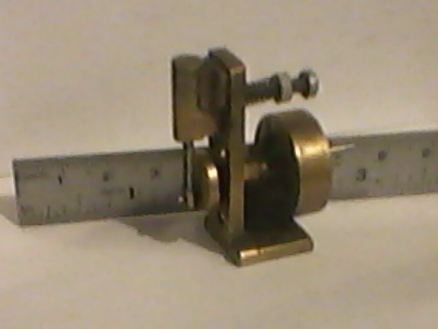
Think i would have worked from the flat side, with packing under the short boss. The thing I'm puzzled about is why you removed the rib between the bosses, just my thoughts, I'd have to see the whole engine to really judge it. Ian S C
Rular – One, such as a monarch or dictator, that rules or governs. 2. A straightedged strip,
as of wood or metal, for drawing straight lines and measuring lengths.
Think I need to take just a couple of thou off the bar supplied for the crankshaft shaft to clean it up and fit the bearings. So I have the bar mounted in the lathe, it has about 5 and a half inches out of the chuck. I've not tried anything that long before. I've managed to set it at the chuck so the dti doesn't move (just a tiny flicker but not moving halfway between the 0.01mm divisions. The tailstock end of the bar has 1 thou deflection over a full revolution but if you slide the dti over the top of the bar for the entire length there is 3 thou difference. It is only a very small (and cheap) Lathe at the end of the day I suppose, I'm hoping that will suffice. I presume I can't take just a couple of thou off the bar though given the 3 thou deflection – have to see how I get on…
(Could someone please yell at me if I'm about to turn a disaster – thanks!)
Cheers
Allan
ps I've just had a thought – I haven't checked the actual diameter of the unturned bar to see how accurate it is end to end – may have something to do with it of course…
Yes I may have made a mistake there – the Stuart drawings don't show the rib and is why I removed it – I have since seen a picture of another model with this left on..
I may yet order another crank from Stuart, think I may make a better job of it second time around now..
The 0.003" along teh bar suggests the tailstock is not inline with the headstock and if you make a cut you will end up with a bar that tapers 0.006" over its length.
Just going to have my dinner then I'll suggest what to do if nobody else does in the meantime.
Just read your post again as the difference is along th etop there is not a lot you can easily do to improve things. Make sure there is no swarf traped between the bed & tailstock, try taking out the centre and putting it back in another position as it may not be perfectly true and at the same time check there is no muck in the taper socket stopping the ctr seating correctly.
The other thing to think about is is turning the rod down the best option. Its likely to be an imperial bar of nominal 7/16" dia which usually comes out a thou or two under size so rather than try to take it down to 11mm and not get such a good finish on the bar you may be better off reaming the holes out to 7/16"
Having sweated blood to turn crankshafts parallel over several inches, I wuld say a beginner is likely to make it too small before getting an ideal finish and suitably parallel. I would just polish the bar up and be happy.
As I recall the stuart 10 uses 7/16 bar straight out of the box.
The shoulder between the two diameters is not as square as it should be I think.
The micrometer readings for the ends of the main diameter came out at 10.95mm for the crank end and 10.97mm for the other – I think beginners luck was at work..The fit in the bearings seems nice – maybe too close.
Turning the small diameter on the shaft.
The shaft, just needing the crosspin hole. (the brown colour is just a reflection..)
Can anyone please tell me if it would be ok to fit the crank to the shaft and then drill through both to fit the crosspin (in the small diameter) or should both be drilled separately – it would seem easier to drill both at the same time? Thanks.
Allan Is there any reason why you have such a long piece sticking out of the chuck ? A centre in the tail stock and the tail stock seems to be extended will flex You shoyuld turn as near the chuck as possible Just a suggestion
Sorry, the description for that photo is misleading – I had to turn down the entire length. The supplied bar for the shaft was I think 11.1+mm, I only had an 11mm reamer for the bearings so I had to cleanup a little. I could maybe do with an adjustable reamer set..
The tailstock is extended to reach over the saddle in order to get the tool to the end of the bar – the Lathe is very small and sometimes a bit short on space. Although that being said I am very very pleased with it – SIEG SC4.
You say ;- " I could maybe do with an adjustable reamer set.."
My personal experience of adjustable reamers is that they are inventions of the devil and my advice is to shun them! However there may be others here who would advise differently and, if so, I too would be pleased for those comments.
Roy is quite right and I'm pretty sure that you will find that the sizes for the Victoria are Imperial thus 11.1 mm = 7/16 in.
A lot of the Stuart engines have common parts and , many years ago *, I built the Stuart Turner "Real" – I think the flywheel is the same as the Victoria – and it certainly has a 7/16 in hole.
[ * "Many years ago" – I entered my model "Real" in the Midlands Model Engineering Exhibition – there is a little plaque, awarded to all entrants, on the base saying this was 1983 – how time flies! I would post a picture but when I look at it closely it's in a disgustingly dirty state – so perhaps not! ]
Thanks for the info, I have been converting all measurements into metric since what little drills etc I have are all in metric, but I am beginning to see that sometimes it pays to think and stay in imperial…
Roy you are quite right I am a complete novice to model engineering, but have had a lifelong interest / passion for the 'old' mechanical world, especially steam – I've never had the chance to attempt Model Engineering until recently – all my working life I (like all too many nowadays) I have always worked all the hours going with no time for anything else..
I did about 35 or so years ago have an apprenticeship as a fitter / turner with British Steel and spent a couple of years training on the Lathe etc – but apart from remembering that I loved it I have forgotton all the info (but not the people) – I had to leave to find better paid work at the time.. Every now and then I come across or do something that I can remember and it brings back some great memories.. There were a lot of very skilled men there then (all over the country in those days..) – can't help but feel sad they and the skills have mostly dissappeared. There are many extremely skilled people on here of course – I dont know how much longer they will put up with my endless simple questions!
This is my first real project although about a year ago I did complete a 'simple oscillating steam engine' from bar stock and plans that I found on the internet – this is my first to include any castings and fittings etc… At the risk of it lowering the tone of the site there is a pic below, a simple thing I know and not very well done, but I absolutely loved doing it. A house move has come between now and then..
Just to say that I've been waiting for a new crank to arrive, after being made aware on here how important it is to get the bores parrallel I was not confident I had done so at my first attempt – I had done it on the drill – although it looked ok to the eye (mine anyway). I can see that I would have been better to have set it up properly on the Lathe and done it there. Hoping it may arrive today or very soon as it's been ordered a few days now….
Heres one I built a good many years ago, it's similar to one that featured in an article in ME, think it was called Grandma's / Aunties (something like that) broach, it has a 3 mm bore, and a 6 mm stroke, the flywheel is 22 mm dia, and give it 40 psi and it buzzes like a bumble bee. I had it in a little tin boat, and sailed it on the lake at the local Recreation Centre, It would do the length (about 100m)on a filling of the little boiler. Ian S C