Stuart victoria

Advert

Stuart victoria

Home Forums General Questions Stuart victoria

Viewing 23 posts - 76 through 98 (of 98 total)
  • Author
    Posts
  • #525720
    Former Member
    Participant
      @formermember12892

      [This posting has been removed]

      Advert
      #525726
      Howard Lewis
      Participant
        @howardlewis46836

        Ignoring, for the moment, the various Design Changes to components, and working from basics..

        ASSUMING that the cylinder centreline is the same height from the bedplate as the Crankshaft centreline, the piston stroke will be twice the throw of the crankshaft ( [Crankpin center to Crankshaft centre] x 2 )

        To allow the engine to rotate, the distance between the standards for the Slide Bars must be greater than the Stroke. This difference will be twice the design clearance between Crosshead and Slide Bar standards.

        The Con Rod Centres should be Crank Pin Centre to Gudgeon Pin centre, with the Cross Head clear of the Slide bar Standards by the designed Crosshead to Standard clearance, at Inner and Outer Dead Centres.

        The Piston Rod length should be such that at Inner or Outer Dead Centre, the Centre of the Gudgeon Pin bore just provides the clearance at each end of the cylinder.

        Some designs might attempt to cater for the difference in effective Piston area, on each side, by allowing more clearance on the Piston Head side than on the Rod side. The rights and wrongs of this approach should not enter into this discussion, unless the basic design dimensions suggests that this is the case here.

        Far easier, (but theoretically wrong, perhaps ), to aim for equal clearance at both ends.

        Having taken some dimensions, it should be possible to find the dimensions for Con Rod Centres, and Piston Rod length, for THAT particular engine, which may differ from the dimension shown on a drawing, especially if the drawings are at different Design Change levels.

        HTH

        Howard

        #525735
        Ramon Wilson
        Participant
          @ramonwilson3

          Posted by Howard Lewis on 08/02/2021 16:05:10:

          Ignoring, for the moment, the various Design Changes to components, and working from basics……

          …. Having taken some dimensions, it should be possible to find the dimensions for Con Rod Centres, and Piston Rod length, for THAT particular engine, which may differ from the dimension shown on a drawing, especially if the drawings are at different Design Change levels.

          Well I never Howard – who would have thought it could be so fundamentally straight forward laugh

          Sorry Howard – could stop myself wink

          Best regards – Ramon (Tug)

          #525968
          Howard Lewis
          Participant
            @howardlewis46836

            Well Tug,

            There has been a lot of toing and froing about the dimensions on drawings, which seem to take little account of what mixture of parts are actually in THIS particular engine.

            The lack of errata for the drawings (ie documenting Design Changes ) is NO help, and may well account for the problems.

            I have seen a LOT of Design Changes and keeping all the parts compatible can be quite daunting.

            I have come across some right hybrids; Bolts with A/F heads and Whitworth threads was one, liable to result in damage to one or other of the mating parts.

            An engine that failed despite everything being correct to drawing; until it was pointed out that two parts of an assembly have moved relative to each other!.

            Hence my suggestion to start measuring to find out what dimensions the parts should be.

            The problem really seems to be to arrive at a set of components that actually allow THIS particular engine to function.

            If all else fails, go back to first principles. Fine tuning can vastly improve function

            Howard

            #525977
            Former Member
            Participant
              @formermember12892

              [This posting has been removed]

              #525983
              JasonB
              Moderator
                @jasonb

                Howard. I think Ramon's comment was based on the fact we have been saying to make the piston rod and conrod length to suit what has been built for the last 3 pages of this thread.

                The discussion of drawing is to try and see where the error may have come from in the first place so that others can avoid the same problem..

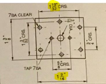
                Even with the correction sheets I have found errors that they don't seem to cover, anyone able to make this to the sizes shown?

                vicky cover.jpg

                Edited By JasonB on 09/02/2021 18:38:01

                #526008
                Howard Lewis
                Participant
                  @howardlewis46836

                  Jason,

                  Coming from a high volume manufacturing background, it saddens me that there seem to be so many comments about inaccuracies in model engineering drawings (Almost as many as my typos )

                  No wonder that so many models, supposedly made to the same plans, differ, apart from the modeller putting his or her particular shine upon it as well.

                  I can understand someone not familiar with caucasian numerals confusing a badly written 0 for a 6 or vice versa (Am sure that accounts for some of the errors in the chart that came with my HV6 )

                  Howard

                  #526012
                  JasonB
                  Moderator
                    @jasonb

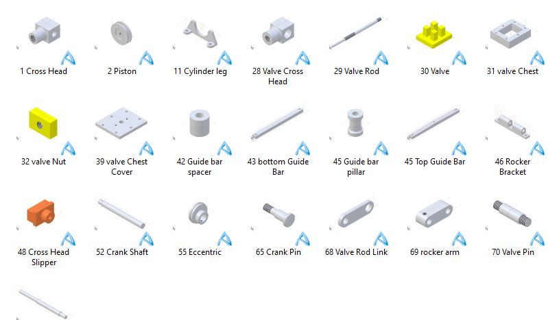
                    So far it's the only error that has jumped out at me having started to draw up the parts from the more recent drawings though I have yet to assemble it on screen.

                    vicky parts.jpg


                    Biggest problem will be deciding do I make it with parts as per Stuarts, make small alterations for what I would prefer to see or do a lot more extensive reworking. Either way I think I will stick with imperial as most builders buying a kit will be loath to put all the stock and fixings into the come in handy box. If Stuarts were able to offer a "castings only" it then that would be a different matter. I must say although I'm happy to work in both trying to sort these drawings out with all there fractions would have ben a lot easier if it were metric as it's easier to do a lot of it in your head.

                    Maybe a metric version will be the reserve of the fabricate and cut from solid brigadewink 2

                    Edited By JasonB on 09/02/2021 19:41:29

                    #526016
                    Former Member
                    Participant
                      @formermember12892

                      [This posting has been removed]

                      #526017
                      Andy_C
                      Participant
                        @andy_c

                        Jason, the size shown on my set of drawings is very clear and reads 1 9/32 and 1 9/16 respectively referring to your highlighted dimensions.

                        #526020
                        Former Member
                        Participant
                          @formermember12892

                          [This posting has been removed]

                          #526033
                          David Caunt
                          Participant
                            @davidcaunt67674

                            Jason,

                            The 1/32" would hardly take the 7BA clearance holes. Not looking for anything else.

                            Dave.

                            #526042
                            Ramon Wilson
                            Participant
                              @ramonwilson3

                              Hello Howard,

                              Yes Jason is right – that was very tongue in cheek and irresistable I'm afraid but no offence was meant I assure you.

                              From the outset I saw this as fixable as is without recourse to sorting out the errors in the drawings.

                              I do agree though, and it has not been only my thoughts on the matter over the years, that the drawings we find ourselves with are at time less than favourable to say the least. Possibly an acceptable irritation for those with the skill and knowledge to see the errors but many have been caught by mistakes – but, 'tis a true old saying if you haven't made a mistake you haven't made anything and drawings do have mistakes despite the best will of the designer at times.

                              The finest drawings I have worked to from a ME point of view were those provided for the Lang Bridge engine by Helix Engineering – absolutely faultless. I won't comment on the most frustrating but theres certainly been a few to fit that bill.

                              Hopefully Arthur will get his Victoria running which is to me the main aim – irrespective of dimensional accuracy – which for me is far more important than knowing that everything is as designed to the 'n'th degree.

                              I think we are all singing from the same hymn sheet on Arthur's behalf for that.

                              Regards – Ramon (Tug)

                              #526063
                              JasonB
                              Moderator
                                @jasonb

                                Andy, Br, David. The valve chest cover drawing is correct on the older version being 1 9/32" rather than 1 19/32" which allows the holes to be drilled within the plate rather than outside it!

                                #528373
                                JasonB
                                Moderator
                                  @jasonb

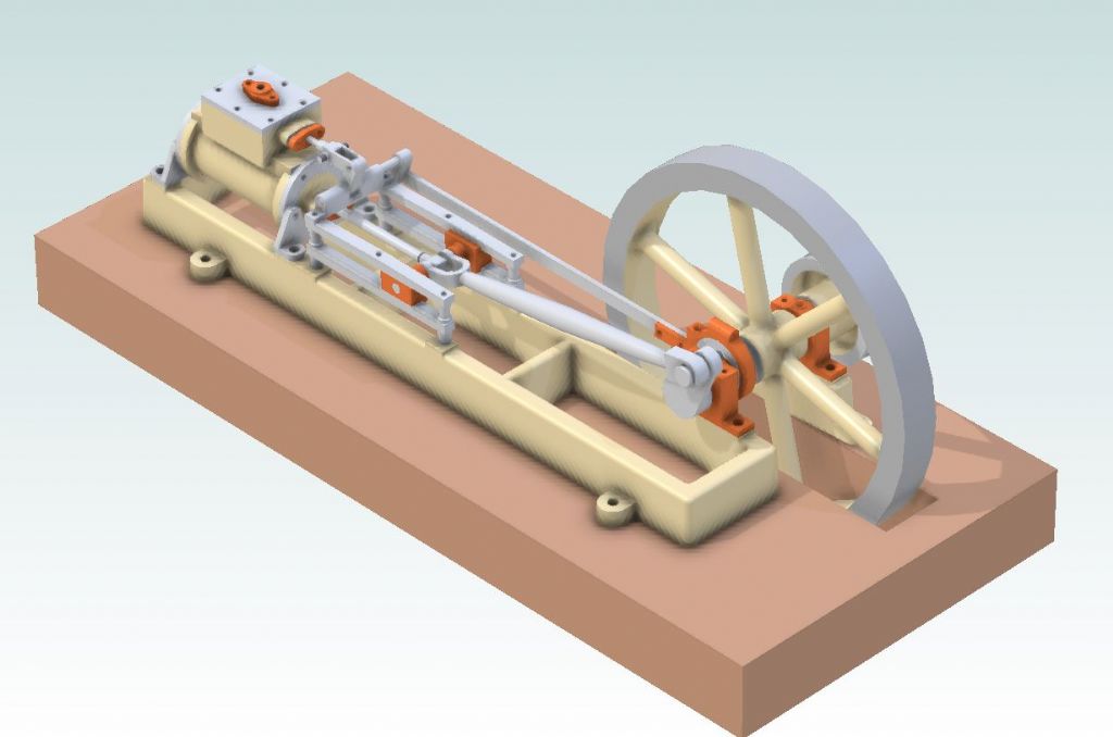
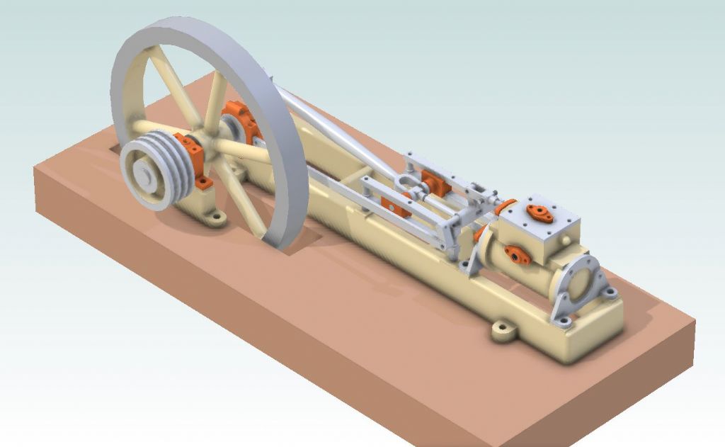
                                  Well thanks to a very generous forum member I have been able to get my grubby little mitts on a set of Victoria castings and model it in 3D using Alibre. I'll post a few dimensioned drawings of the base, conrod and piston rod assembly in the next few days as that is what this thread is concerned with then post some more once the new forum software is up and running. here is a little of what's to come.

                                  vicky1.jpg

                                  vicky2.jpg

                                  #535254
                                  JasonB
                                  Moderator
                                    @jasonb

                                    Well I decided to prove my drawings before posting and as the Change in software is imminent will probably hold off until then.

                                    Looking at the dates on my photos I first started on the main bed casting on 26th of Feb and today had enough done to see if the engine ran. There was some work already done but I have reworked quite a bit and also had to make a few missing bits from scratch so probably a similar amount of work to starting with a virgin kit.

                                    In the video it is just running as a quick trial so no rings, gland packing or gaskets and the outrigger bearing is not held down so it starts to move about a bit at speed and knock but who wants to run them like that anyway when a slow tickover is as nice to watch as any clock or pendulum.

                                    #535504
                                    Ron Laden
                                    Participant
                                      @ronladen17547

                                      Lovely Jason and I agree much nicer at tickover something very satisfying about it.

                                      Ron

                                      #535520
                                      JasonB
                                      Moderator
                                        @jasonb

                                        Thanks Ron

                                        #535554
                                        Roderick Jenkins
                                        Participant
                                          @roderickjenkins93242

                                          Sweet smiley

                                          Rod

                                          #535562
                                          mechman48
                                          Participant
                                            @mechman48

                                            I like it, smooth running.. not the Jamaican bob sleigh team… or was that 'cool running'?..devil

                                            George.

                                            #535571
                                            Ron Laden
                                            Participant
                                              @ronladen17547

                                              Jason, would it be considered as a long stroke engine it seems to have a fair length of stroke and the cylinder looks a decent length to, just wondered.

                                              Ron

                                              #535573
                                              JasonB
                                              Moderator
                                                @jasonb

                                                The majority of "mill" engines were quite slow running and always tend to have a long stroke in relation to the bore, in this case it's double with a 2" stroke and 1" bore. The one that is just about to start being serialised in ME is 46mm stroke x 24mm bore so again similar long stroke.

                                                The higher revving engines would tend to be very close or even square with equal bore and stroke

                                                #539189
                                                JasonB
                                                Moderator
                                                  @jasonb

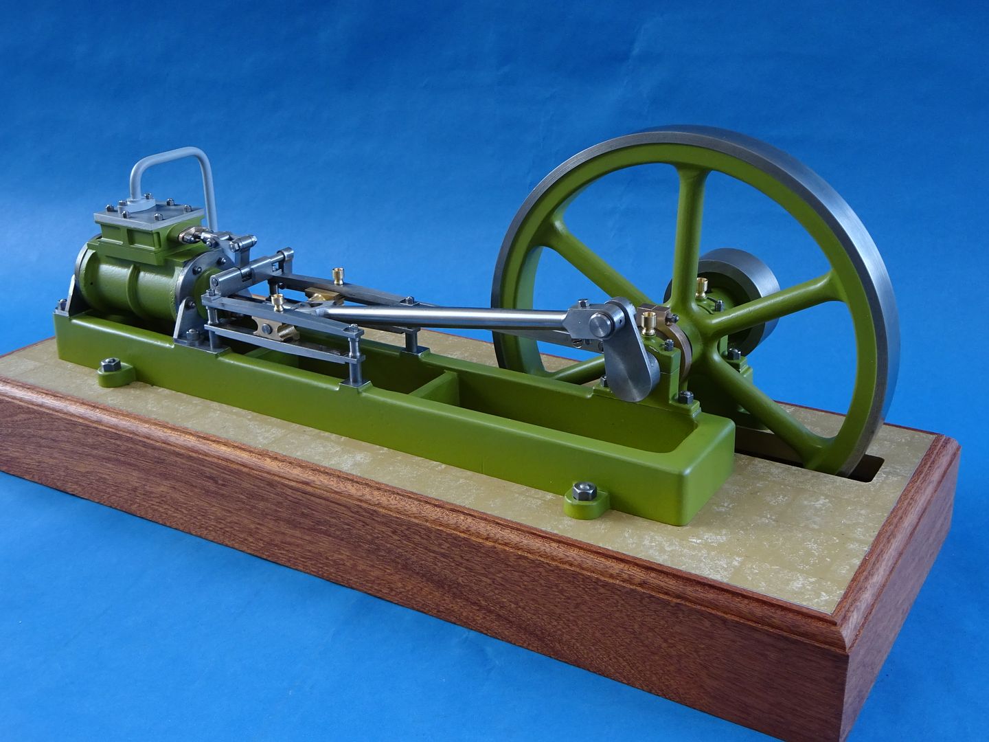
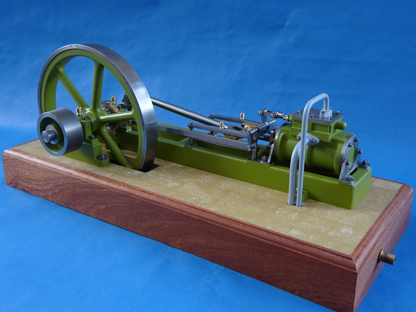
                                                  Well I had a change of plan on the colour as the cream I had thought of using is no longer available so found a tin of something suitable in the back of a draw and sprayed that on then stuck it on a base.

                                                  The eagle eyed will see that I have added a bit of extra detail to the cylinder and valve chest as well as getting rid of the bolt together eccentric rod, apart from that it's fairly stock except for the corrected dimensions which will hopefully follow soon.

                                                Viewing 23 posts - 76 through 98 (of 98 total)
                                                • Please log in to reply to this topic. Registering is free and easy using the links on the menu at the top of this page.

                                                Advert

                                                Latest Replies

                                                Home Forums General Questions Topics

                                                Viewing 25 topics - 1 through 25 (of 25 total)
                                                Viewing 25 topics - 1 through 25 (of 25 total)

                                                View full reply list.

                                                Advert

                                                Newsletter Sign-up