Stuart Twin Victoria (Princess Royal) Mill Engine

Advert

Stuart Twin Victoria (Princess Royal) Mill Engine

Home Forums Work In Progress and completed items Stuart Twin Victoria (Princess Royal) Mill Engine

Viewing 25 posts - 201 through 225 (of 1,206 total)
  • Author
    Posts
  • #550479
    Clive Brown 1
    Participant
      @clivebrown1

      Apologies, I hadn't twigged that your proposed feet were integral with the cylinder. I was going by my "single". Should've looked at the diagrams more closely,embarrassed.

      In fact, from looking at Google images, are both types of foot used for the twin?

      Advert
      #550482
      Dr_GMJN
      Participant
        @dr_gmjn

        Clive, this is the “Princess Royal” version of the Twin Victoria, which has quite a few modifications to the standard model (as explained in the first post). Cheers.

        #550484
        Clive Brown 1
        Participant
          @clivebrown1
          Posted by Dr_GMJN on 19/06/2021 19:09:23:

          Clive, this is the “Princess Royal” version of the Twin Victoria, which has quite a few modifications to the standard model (as explained in the first post). Cheers.

          Thanks, must read complete threads in future before jumping in. Even if it means changing the habits of a lifetime smiley.

          #550486
          Dr_GMJN
          Participant
            @dr_gmjn
            Posted by Clive Brown 1 on 19/06/2021 19:28:17:

            Posted by Dr_GMJN on 19/06/2021 19:09:23:

            Clive, this is the “Princess Royal” version of the Twin Victoria, which has quite a few modifications to the standard model (as explained in the first post). Cheers.

            Thanks, must read complete threads in future before jumping in. Even if it means changing the habits of a lifetime smiley.

            Nothing much apart from questions from me for the first 7 pages I’m afraid…

            #550491
            Dr_GMJN
            Participant
              @dr_gmjn
              Posted by JasonB on 19/06/2021 13:07:29:

              That's it. The intermittant cut should not be an issue and if you had the "spacers" a little closer together in your sketch then the final cuts will be constant.

              A loose packer at either end will spread the load rather than push against the central soldered in packers, infacct arranged that way you could use superglue rather than solder as then it is only a case of stopping the bits sliding about when initially clamping.

              clamping2.jpg

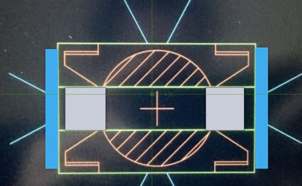
              Actually I was thinking more of the horizontal beams being weak towards the final cuts. I could also use spreaders on the upper and lower bars to spread the clamp force there.

              #550728
              Dr_GMJN
              Participant
                @dr_gmjn

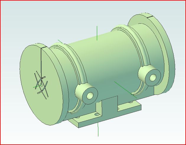
                So I've been pondering the workflow for the cylinders again. I know I've asked about this before, but it's a bit confusing because there are a lot of things that need to be assembled and aligned, and I don't want to end up with cylinder feet that have to be noticeably asymmetric to correct things:

                a) The cylinder axis needs to be aligned with the bed, vertically, horizontally and longitudinally.

                b) The valve face needs to be horizontal and flat (and there's hardly any machining allowance on it).

                c) The feet have to be fixed to the cylinder in such a way that their lower spigots fit snugly between the beds ( I assume), aligned with the existing holes in the bed, and also make the cylinder axis conform with a).

                Current thoughts are:

                1) Make the upper features of the feet exactly to drawing (width, length, circular cylinder seatings, milled bolt recesses and drilled mounting holes, tapered sides drilled, and drilled tapping sized holes for cylinder bolts), but leave the undersides flat, ie no spigot features.

                2) Plug the cylinder bore with centre drilled wooden plugs both ends. Check that the o/ds of the cast flanges are more or less concentric with the plug o/ds (this will make the fettling for fitting the cylinder cladding easier).

                3) Temporarily attach feet to bed, then add the cylinder on top. Confirm that the cylinder axis is aligned with the bed (using the mill DROs, in conjunction with the centre drillings and perhaps a rod through the holes), and – very carefully – ensure that the roughly flatted cast valve face is also nominally horizontal. Then apply JB Weld and allow to cure.

                4) Once set, drill all the way through the cylinder to tapping size using the feet holes as a jig, open up the holes in the feet to be clearance, tap the cylinder, and add the bolts – coated with JB Weld. Once set, remove any bolt ends protruding into the cylinder with a file.

                5) Setup the cylinder on the lathe cross-slide, sitting on its feet and again using the centred wooden plugs as an alignment guide, bore the cylinders.

                6) Fly-cut the piston-rod ends of the cylinders in the same setup.

                7) Transfer the machined cylinder to the mill, and setup on it's feet and mill the valve face, which in theory should be nominally flat, as per 3)

                8) Turn upside down so they cylinder sits on the valve face, align longitudinally, and machine the feet undersides to be a snug fit in the beds.

                That should get me in the ballpark of them being right by default, but I'm a bit concerned that the side-to-side alignment will have no adjustment. I'm assuming that the lower spigots on the feet are intended to be a fit on the beds (otherwise what's the point of them?). Obviously any horizontal drop or rise of the axis can be corrected with shims or more machining if necessary, but in theory I guess it should be right.

                I assume as per usual I'm over-thinking this, so any comments much appreciated!

                #550733
                JasonB
                Moderator
                  @jasonb

                  I think I would only do the arc, 2 "D" shapes and the angled cuts on the feet and get them fixed in position, leave trimming to O/A length, the stepped bottom and the 4 fixing holes until the cylinder has been bored then you can pick up it's position and get the heights and hole positions set from there. Basically create the "casting" first them machine it

                  I don't think the step on the bottom is to provide sideways location as at 1 5/16" it's a lot narrower than the gap between the bedplate casting which is about 1.400". Most likely there to stop the feet becoming too flexible as there would be little material left if they were just flat bottomed.

                  #550741
                  Ramon Wilson
                  Participant
                    @ramonwilson3

                    'Yep' agree with Jason here Doc G, get the feet (over thick) well established to the casting before machining anything yes

                    Said it before but it's worth saying again – personally I would then do the bore(s) first then bring every thing to it – both ends on the lathe held on a mandrel, valve face and feet height on the mill – preferably held on a mandrel or with one face bolted to a good angle plate – all faces, depending on the accuracy of the mandrel true to the bore position. This is a much better way of achieving surfaces true to the bore rather than the bore true to the surfaces much better accuracy and with minimum set ups.

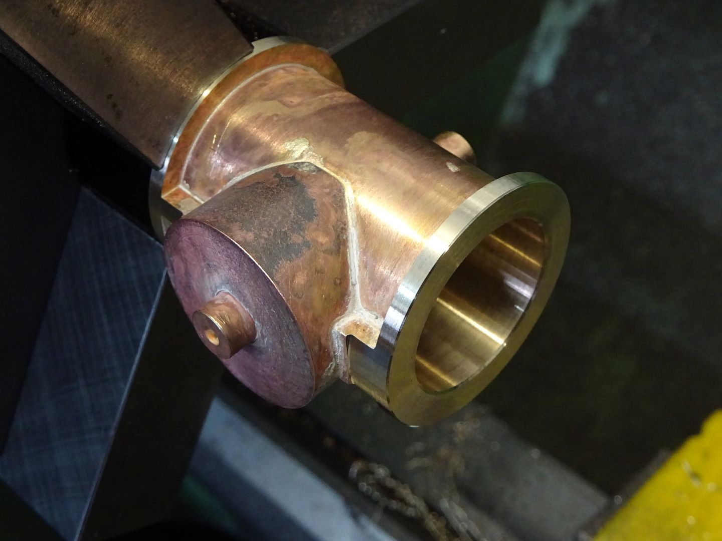
                    All the above ops were done on this Mc Onie cylinder as suggested

                    Hope that helps some Doc

                    Ramon

                    #550752
                    Dr_GMJN
                    Participant
                      @dr_gmjn

                      Jason, Ramon,

                      Thanks both – I know we've been here before, but I'm still not 100%, and this time it's for real. I think basically what I've suggested is what you're suggesting, ie fit the feet to the cylinder, then machine the bore, faces, valve face and finally the feet (or the feet then the face). The methods of doing it are slightly different though.

                      The reason I suggested temporarily fitting the feet to the bed, then confirming the cylinder was square on them before JB welding, was I thought it would at least eliminate the alignment being grossly out, which in turn would mean asymmetric feet somewhere or other.

                      I take Jason's point about leaving the feet overall length until later, and also the spigot not being a tight fit. I think I've confused myself by drawing my own beds, and assuming they were a snug fit. no problem there though, it simplifies things a bit.

                      So that leaves me with a few unknowns – or at least things to confirm:

                      1) Is the centre-marked wooden plug method sound for initial setting of the cylinder on the lather for boring? Thinking put two centres in the head and tail stock and pack/align the cylinder to those? Might use the vertical slide and lock the gibs.

                      2) I'm assuming for milling I clamp the mandrel to the angle plate, check it's level, then datum off it by touching with the cutter on the top to get it's axis position, then clamp the cylinder to it? Then offset for the feet/valve face cuts assuming the mandrel/cylinder axes are coincident?

                      3) Assuming 2 is right, I'd want to mill the valve face first, because I've hardly got any machining allowance there and would want to double-check all around with a height gauge that I'm taking a more or less equal amount off, and not going to crash into the cast inlet port pad. Could do a rough vertical measurement on the feet at the same time as a sanity check But then how do I spin the cylinder to get the feet uppermost, with the valve face exactly parallel with the bed? Clamp the machined face direct to the bed and somehow re-align the cylinder axis?

                      Sorry for the questions, but must admit I'm confused about the alignment details rather than the overall concept of what to do.

                      Thanks.

                      #550760
                      Ramon Wilson
                      Participant
                        @ramonwilson3

                        Hi Doc, I can see your concern but I'm sure you can overcome ityes

                        Okay, lets assume you had bought cylindercastings with integral feet – the first thing would be to create a datum and the largest area would be that covered by the feet . This could be filed or machined to give a reasonable flat surface (but not as yet finished) from which to put in your bore. You would use this face to set up either on an angle plate on the face plate or better still on an angleplate/vertical slide on the cross slide for between centres boring. To my mind you need to create this situation before anything else ie fit the feet firmly in situ with JBW and let it really set before further machining to create that initial datum.

                        If the hole as cast is reasonable then using plugs to get a centre relative to the outer circumference of the cylinder ends is fine but bear in mind getting the bore central to the casting is more important than getting the 'as cast' bore central to the boring bar.

                        Once that bore is finished you now have a datum from which all other faces can be made true. The ends are faced (not fly cut) on the lathe on a mandrel. Mount the mandrel on the mill as suggested and centre the spindle across its diameter. Mount the cylinder as fair as you can with the valve face underneath – still untouched – level with the table. Use a parallel to near fill the space and eye the gap – you'll be surprised how close you can get and certainly close enough here. Bring the feet to a true dimension to the bore – you would need to take care that when JB Welding them in place you ensure a reasonable degree of symmetry to prevent odd thicknesses – and you now have the bottom face true to the bore and at the right height dimension. Remove from the mandrel and clamp to the table (or bolt to a sub plate using the mounting holes in the feet) and take the final cut over the valve face to finish size. Whether you chose to use a fly cutter or small end mill to do this op is up to you but a 6mm cutter over lapped say 4-5 mm will ensure you have a 'flat' face albeit not so pretty.

                        If you find you don't have enough to clean up to size then you could mill it lower and fit (JBW) a false face and re-mill(best) or change the thickness of the valve chest and possibly the valve to suit (not so best)

                        Hope that helps – main thing is to 'have it right' in your own mind before making those first cuts


                        Ramon


                        Edited By Ramon Wilson on 21/06/2021 17:35:24

                        #550765
                        JasonB
                        Moderator
                          @jasonb

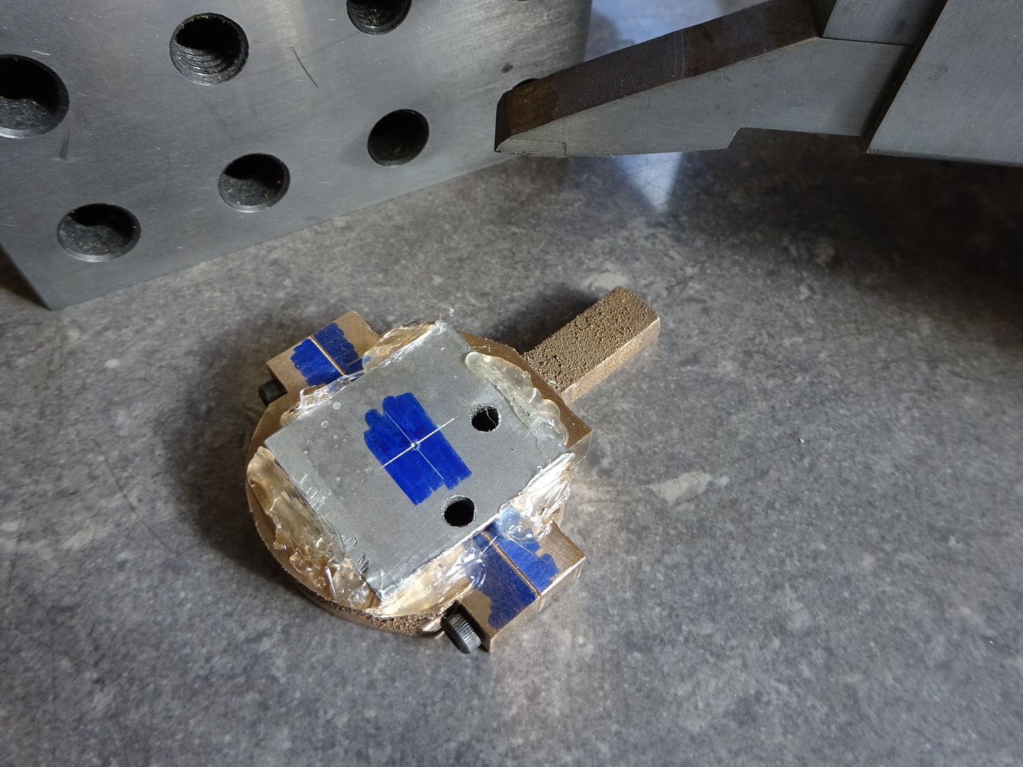
                          Another option to plugging the ends is to stick a thin bit of scrap sheet to the ends with hot melt glue, I use this quite often when there is a hole where I want to put a mark such as the ecc strap on the Victoria.

                          #550767
                          JasonB
                          Moderator
                            @jasonb

                            Just to add, if you are not familiar with the usual way to find the ctr of the casting then striking 4 arcs of aprox half dia will get you close and you them place your ctr mark in the middle of the arcs. If you don't have odd leg callipers then find a bit of bar aprox half flange dia and use that to scribe 4 lines with bar and cylinder on a flat surface. If you have  ascribing block or height gauge that can be used too do the same sort of thing.

                            cylinder layout.jpg

                            Edited By JasonB on 21/06/2021 18:50:35

                            #550805
                            Ramon Wilson
                            Participant
                              @ramonwilson3
                              Posted by JasonB on 21/06/2021 18:29:05:

                              Another option to plugging the ends is to stick a thin bit of scrap sheet to the ends with hot melt glue, I use this quite often when there is a hole where I want to put a mark such as the ecc strap on the Victoria.

                              That's a good tip Jason, well worth keeping in the memory bank yes

                              #550808
                              Dr_GMJN
                              Participant
                                @dr_gmjn

                                Thanks both – is aluminium ok to make the mandrel?

                                Also, I think Jason mentioned fly-cutting the piston-rod end of the cylinder in the lathe, in the same setup as for the boring?

                                #550815
                                Ramon Wilson
                                Participant
                                  @ramonwilson3

                                  In this instance I don't see why not Doc, but I would advise never to make an Ali mandrel to hold an Ali part, the chances of pick up and seizing are potentially far too great.

                                  Why would you want to fly cut the ends when it can be held on a freshly turned mandrel and both ends faced correctly, perfectly square to the bore? Not saying flycutting it it can't or shouldn't be done just not quite sure I see the reasoning behind doing it that way.

                                  Been re -machining a commercial glow motor crankcase today. One mandrel made to suit the main crankase bore and all ops done from that – much the same really


                                  Edited By Ramon Wilson on 21/06/2021 22:48:36

                                  #550824
                                  JasonB
                                  Moderator
                                    @jasonb

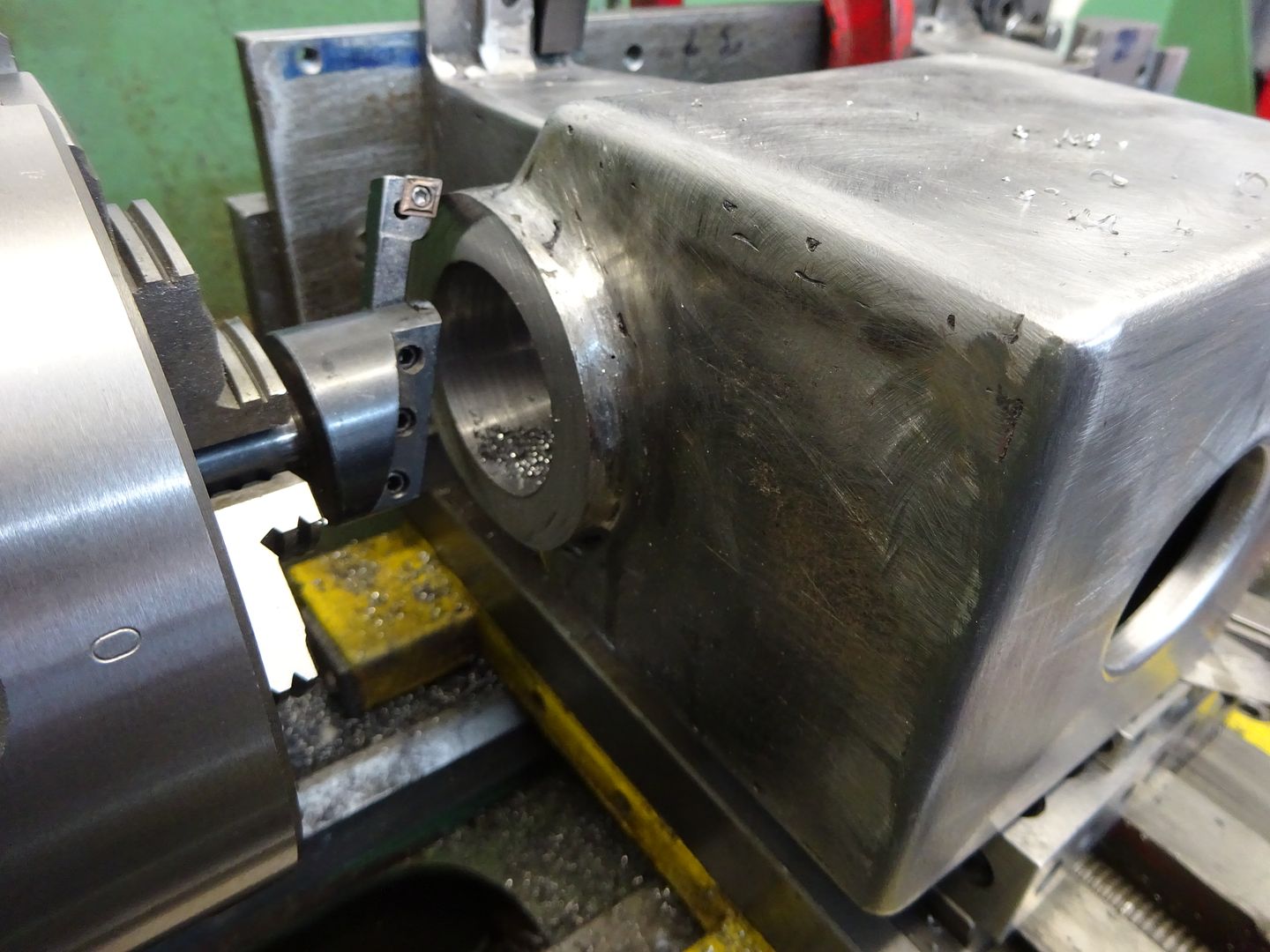
                                    Probably comes from me doing a few larger bores where the casting is too big to turn so the end of the cylinder was flycut at the same setting as that for boring. Bon critical end can be done in other ways such as with cylinder clamped vertically to mill table with flycut end at the bottom so should be true to opposite end. I also tend to do this sort of size cylinder in the 4-jaw so again easy to turn the critical end while it's still in the chuck.

                                    Other reason is it saves making a mandrel and with some of my bores 5-6" long and close to 2" dia thats a big bit of metal.

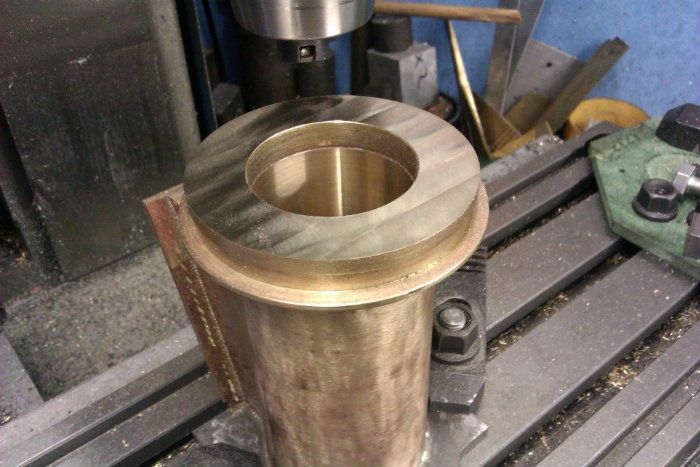
                                    This one was flycut after boring

                                    Don't think I would have enjoyed turning this on a mandrel even if I had a lathe big enough to swing it

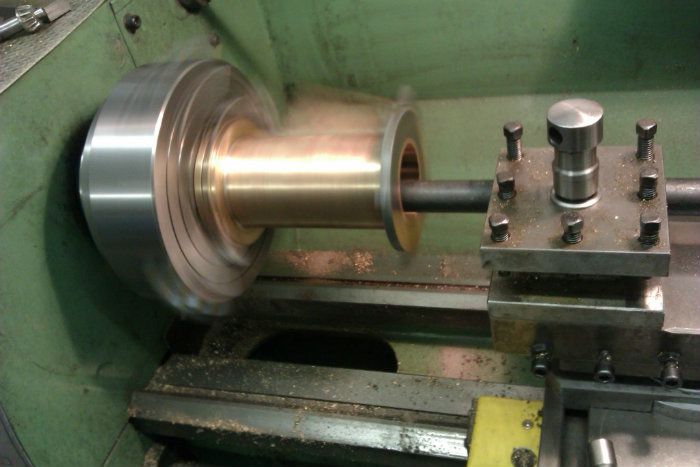
                                    large steam cylinder being bored on the lathe and was also faced at the same setting
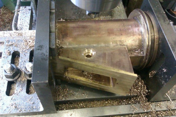
                                    Then clamped to mill table to do the other end
                                    Other ops done with pair of angle plates as mandrel at one end would have quite an overhang
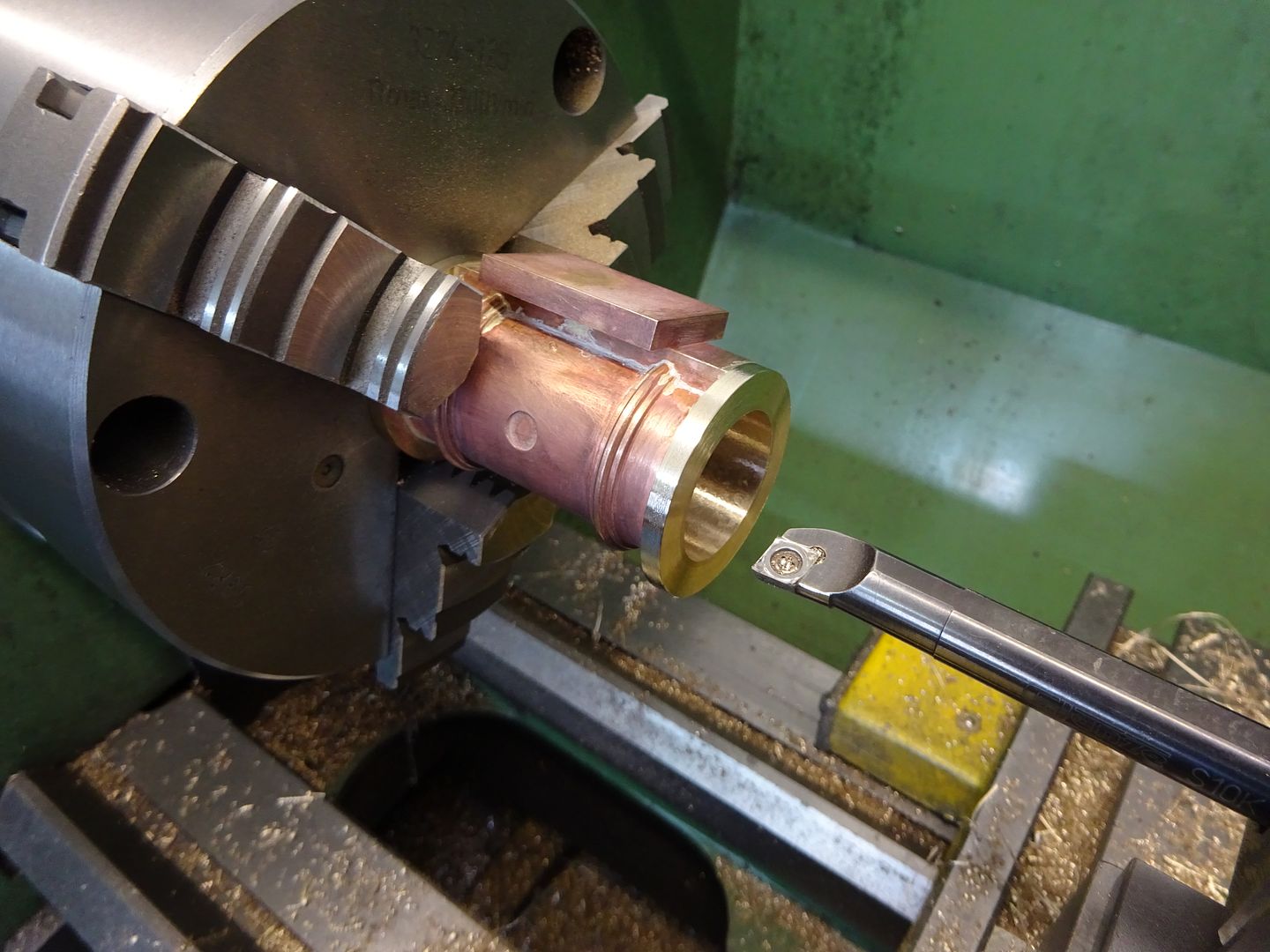
                                    But on these smaller size cylinders as said I tend to use 3 or 4 jaw chuck and bore, face and tidy OD of flange all in one go
                                    Then with machined flange back against chuck face or in soft jaws finish the other end to length
                                    This way seems to work for me and the Mandrel method does for Ramon so take your pic as to what to use. Choice can often be affected buy each individual part and what machines and tooling you have, Ramon's mandrel method also suits making multiples parts well which he often does as you only set the mandrel once and swap the parts over for each op.

                                    #550833
                                    Dr_GMJN
                                    Participant
                                      @dr_gmjn

                                      OK thanks guys – I can now get on with the cylinders. I think the main hurdle – or at least new process – for me to get right is the between centres boring, which I'm keen to try.

                                      First job though is to make the feet.

                                      #550835
                                      JasonB
                                      Moderator
                                        @jasonb

                                        Talking of the feet, I just realised the thicker stepped bottom gives enough depth for the drain cock holes, if they were flat right across there would not be much metal to get a decent depth of thread into.

                                        I see TC suggests either option for doing the flanges and suspect a lot of cylinders have had them turned at the same setting as boring as all the books on making the engines that use this cylinder casting do it that way

                                        #550837
                                        Ramon Wilson
                                        Participant
                                          @ramonwilson3

                                          Yes Jason, quite see your point – as usual it's 'horses for courses' and I had overlooked that you do tackle much larger parts than I usually do – looks at times you are pushing your lathe and mill capacity to the limit with great results yes

                                          The ability to change parts or remove and replace is definitely a bonus when using mandrels as you say however.

                                          Looking forwards to more progress Doc

                                          Ramon

                                          #550884
                                          Dr_GMJN
                                          Participant
                                            @dr_gmjn
                                            Posted by JasonB on 22/06/2021 08:28:05:

                                            Talking of the feet, I just realised the thicker stepped bottom gives enough depth for the drain cock holes, if they were flat right across there would not be much metal to get a decent depth of thread into.

                                            I see TC suggests either option for doing the flanges and suspect a lot of cylinders have had them turned at the same setting as boring as all the books on making the engines that use this cylinder casting do it that way

                                            I think if the feet were cut straight across, the cut would intersect the circle, and you’d have two halves rather than one foot (see 2D CAD a few posts back). I’ll have to double check that, because the remaining material still looks thin. That’s why I was asking about clamping the three bits in the Chuck – by the time the circle is bored out, it looks to me like the pieces could bend under the Chuck jaw loads. A spreader would help with this, similar to what you had at the sides of the three piece assembly.

                                            #550886
                                            JasonB
                                            Moderator
                                              @jasonb

                                              There won't be much meat, maybe 2mm so would not hurt to slip a bit of packing in each side.

                                              I don't think you have a boring head otherwise it could be done in the mill and the vice jaws would grip along the whole length rather than just a point load on the thinnest part, you could even get away without soldering with that setup.

                                              #550930
                                              Dr_GMJN
                                              Participant
                                                @dr_gmjn

                                                No, I do t have a boring head.

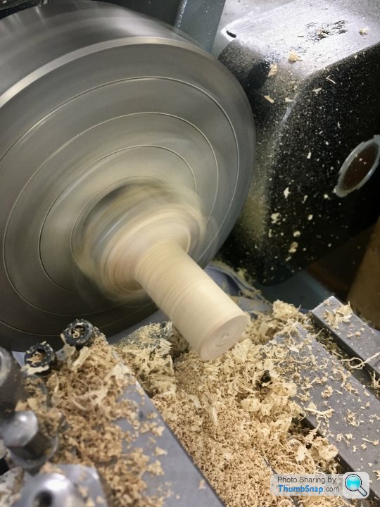
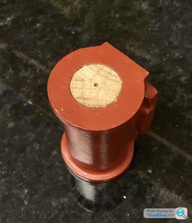
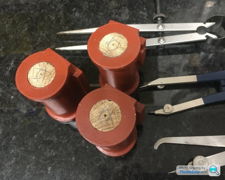
                                                Anyway, I made some centre plugs for the cylinders,

                                                and checked them using the arc method, scribing a circle with dividers and going round with the odd leg callipers:

                                                Most are pretty good, might re-do a couple, although they might be ok, but a bit oval.

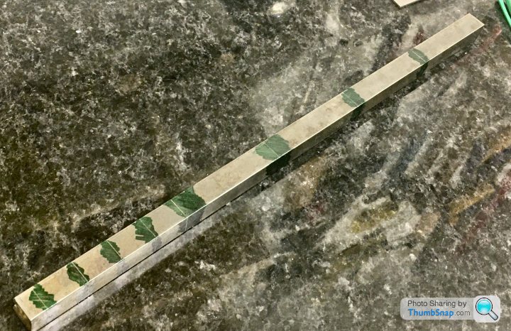
                                                Also divided the 1/2” square bar up for the feet. Just enough in the end, using short middle bits:

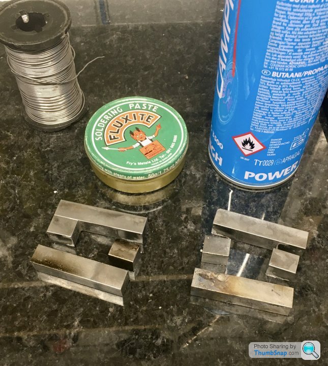
                                                I milled them to consistent lengths, and they are a bit oversized so I can trim them once fitted:

                                                Didn’t have much luck soldering them together, the solder only seemed to capillary into a tiny bit of the cleaned and fluxed joints. I tried to tin the mating faces, but they weren’t having any of it…a slight tap saw them fall apart…

                                                Perhaps the wrong flux, or not enough heat (propane/butane mix)?

                                                Anyway some progress at least. Thanks.

                                                #550933
                                                JasonB
                                                Moderator
                                                  @jasonb

                                                  that flux should have been ok so probably not enough heat to get a the metal upto temp. Tin and sweat is the best method

                                                  #550947
                                                  Ramon Wilson
                                                  Participant
                                                    @ramonwilson3

                                                    How were you holding the pieces together Doc? As Jason says tinning the faces is best but the parts need to be in sufficient contact without being too tight together.


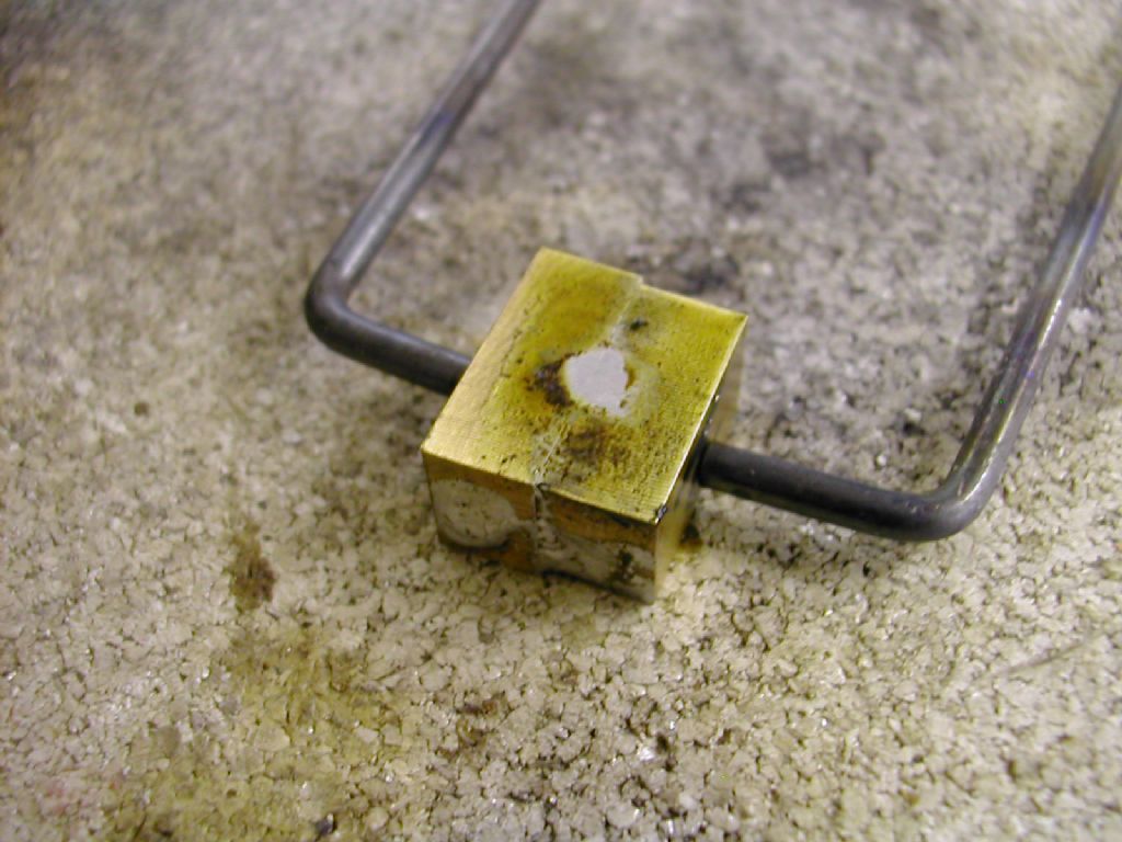
                                                    You could try this – a piece of 14-12 swg piano wire bent as a two pronged clamp. Gives just enough pressure to allow the solder to flow. Well flux the parts and put a blob of solder across the joint then heat gently and uniformly until you see the solder flow

                                                    dscn3727.jpg

                                                    Idealy it wants to lay on something non heat absorbent – this is a piece of Skamoflex -perfect for this sort of op.


                                                    Edited By Ramon Wilson on 22/06/2021 22:27:36

                                                    #550952
                                                    Dr_GMJN
                                                    Participant
                                                      @dr_gmjn

                                                      Thanks both. I was using screw clamps, with flux between the parts, and heating each joint and dabbing with solder until a blob formed, and – sort of – ran into/around the joint. I guess it was too tight a join.

                                                      I did wonder about some kind in sprung clamp in conjunction with tinned surfaces, but never got them tinned in the first place.

                                                      Not sure I’ve got any insulating material. I tried to retain heat by doing it on wood, but of course it started to smoke. Maybe an old concrete block?

                                                      Anyway, I’ll try again tomorrow with piano wire. Cheers.

                                                    Viewing 25 posts - 201 through 225 (of 1,206 total)
                                                    • Please log in to reply to this topic. Registering is free and easy using the links on the menu at the top of this page.

                                                    Advert

                                                    Latest Replies

                                                    Viewing 25 topics - 1 through 25 (of 25 total)
                                                    Viewing 25 topics - 1 through 25 (of 25 total)

                                                    View full reply list.

                                                    Advert

                                                    Newsletter Sign-up