Stuart Twin Victoria (Princess Royal) Mill Engine

Advert

Stuart Twin Victoria (Princess Royal) Mill Engine

Home Forums Work In Progress and completed items Stuart Twin Victoria (Princess Royal) Mill Engine

Viewing 25 posts - 126 through 150 (of 1,206 total)
  • Author
    Posts
  • #533581
    Dominic Bramley
    Participant
      @dominicbramley60728

      Following this thread with interest as I have the Twin Vic kit and plan to make the Princess Royal with it at some point. I had not appreciated that the modern flywheels would cause a problem with the barring rack and no doubt would have come-a-cropper when I got to that point.

      Doc – I have no idea as to how laser cutting services price their jobs – but if there is any significant economy in getting multiples cut – then I'd be happy to go halves with you on a pair when it comes to getting the ring cut.

      Cheers

      Dom

      Advert
      #535419
      Dr_GMJN
      Participant
        @dr_gmjn
        Posted by Dominic Bramley on 13/03/2021 12:24:24:

        Following this thread with interest as I have the Twin Vic kit and plan to make the Princess Royal with it at some point. I had not appreciated that the modern flywheels would cause a problem with the barring rack and no doubt would have come-a-cropper when I got to that point.

        Doc – I have no idea as to how laser cutting services price their jobs – but if there is any significant economy in getting multiples cut – then I'd be happy to go halves with you on a pair when it comes to getting the ring cut.

        Cheers

        Dom

        Dom, yes I’ll let you know.

        #535420
        Dr_GMJN
        Participant
          @dr_gmjn

          About the only thing I’m fit for today, after the sledgehammer side effects of the Covid jab, is reading, so I’m going through the P.R. article again.

          Re the flywheel, it says “Machine the face and the boss, line and line across..”

          What does that mean?

          Thanks.

          #536610
          Dr_GMJN
          Participant
            @dr_gmjn

            Still puzzling over the connecting rods. It says to machine the rods down to 0.3” between the lines that mark the extents of the radiused transitions. Then switch to a tool with a 5/32” true radius, to form the transition radius as the middle diameter is reduced. But if you’ve just reduced the diameter between the extents with a step, how will the radiussed tool get rid of the step? You appear to be trying to form an internal radius where you’ve just put a corner, ie you need to add material.

            #536629
            JasonB
            Moderator
              @jasonb
              Posted by Dr_GMJN on 27/03/2021 22:22:23:

              It says to machine the rods down to 0.3” between the lines that mark the extents of the radiused transitions.

              The "lines are where the radius meets the taper so you are first turning to where the radiu starts and the second tool will then traverse further to the extent of the radius.

              extent.jpg

              I'll have a look at the other bit.

              J

              PS I was like that on Friday after having mine on Thursday with what felt like the Flu.

              Edited By JasonB on 28/03/2021 07:53:15

              #536634
              JasonB
              Moderator
                @jasonb

                Line & line across looks like he just means face the hub back to the same plane that the side of the rim cleaned up to

                #536692
                Dr_GMJN
                Participant
                  @dr_gmjn
                  Posted by JasonB on 28/03/2021 07:00:41:

                  Posted by Dr_GMJN on 27/03/2021 22:22:23:

                  It says to machine the rods down to 0.3” between the lines that mark the extents of the radiused transitions.

                  The "lines are where the radius meets the taper so you are first turning to where the radiu starts and the second tool will then traverse further to the extent of the radius.

                  extent.jpg

                  I'll have a look at the other bit.

                  J

                  PS I was like that on Friday after having mine on Thursday with what felt like the Flu.

                  Edited By JasonB on 28/03/2021 07:53:15

                  Thanks Jason, that would make more sense, but it’s not what it says in the instructions. The dimensions in the drawing are to the edge of the radius on the rectangular bits, not the circular section rod. Those same dimensions are also in the text, where it says to initially machine down between them. If you follow the written instructions, I think the radius would crash into the first set of bolt holes for the strap.

                  It also says to mark the extents of the initial thinning with a felt-tip, but then once machined, to use a rule to find the extents of the rad. In that case why would you need a rule? It’s the same dimensions (there are no others), and you’ve just made a machined step to them, so it’s obvious where it is? There’s some error somewhere because you can’t use the same dimensions for both operations and end up with a smooth transition.

                  I think what he meant was to add on the tip radius to the distance from the ends (ie he shouldn’t have quoted the drawing values for that initial operation) and as you say machine initially to that. Then mark with a felt tip and extend as necessary. Why you’d need a felt tip for one job and a rule for the other is also confusing to me – surely you’d just mark the initial length, and the final length and work to those? For me, the instructions are almost too detailed in this case because they seem to suggest different marking techniques for the same simple job.

                  May well have misunderstood something, and I want to make sure I’m not scrapping a part because of this.

                  #536751
                  JasonB
                  Moderator
                    @jasonb

                    Yes there is something wrong with how it's written.

                    I would put a sharpie mark where I have put the pink lines on that image as they are easy to see while you rough out without the need to keep stopping and take measurements or have to scribe a deep line across the finished face of the ends. This will knock all the corners off and get you down to a round section.

                    Now that you have roughed out change tool and cut the tapers forming the fillets at the same time either measuring or setting a stop, usually a bit of both is needed as the curve of the tool will extend further along the deeper it gets into the work.

                    #536766
                    Dr_GMJN
                    Participant
                      @dr_gmjn
                      Posted by JasonB on 28/03/2021 18:22:19:

                      Yes there is something wrong with how it's written.

                      I would put a sharpie mark where I have put the pink lines on that image as they are easy to see while you rough out without the need to keep stopping and take measurements or have to scribe a deep line across the finished face of the ends. This will knock all the corners off and get you down to a round section.

                      Now that you have roughed out change tool and cut the tapers forming the fillets at the same time either measuring or setting a stop, usually a bit of both is needed as the curve of the tool will extend further along the deeper it gets into the work.

                      Yep, that all makes sense.

                      When I’m grinding the radiussed tool (planning on doing it on the linisher), are you supposed to harden it afterwards? Maybe dunk in water after grinding or something?
                      Presumably I can draw the profile on the tool and work to that, estimating the angles?

                      Is there a special file for sharpening tools, or is it a case of re-grinding when the cut isn’t as good?

                      New to all this – Thanks.

                      #536773
                      JasonB
                      Moderator
                        @jasonb

                        If you are grinding an HSS blank then it can be used as is. If grinding from gauge plate/silver steel then it will need hardening.

                        Tough up with a slip stone or more likely these days a small diamond lap if the edge goes off, this can be used on both materials

                        #536849
                        Dr_GMJN
                        Participant
                          @dr_gmjn
                          Posted by JasonB on 28/03/2021 19:45:29:

                          If you are grinding an HSS blank then it can be used as is. If grinding from gauge plate/silver steel then it will need hardening.

                          Tough up with a slip stone or more likely these days a small diamond lap if the edge goes off, this can be used on both materials

                          Ok Thanks.

                          #537182
                          Dr_GMJN
                          Participant
                            @dr_gmjn
                            Posted by JasonB on 08/03/2021 13:29:38:

                            Clamp to cross slide with packing or to the Vertical slide of you have one. Flycut the end. Put DTI in lathe chuck and adjust bar's position until dti shows it's true and ctr drill with drill in spindle. I have used the wooden block method Ramon mentions in the past when I did not have a fixed steady for the Emco

                            Strictly speaking the holes do not need to be spot on but it's handy for measuring tool projection though that can be got around by turning down a section around the toolbit hole to a known diameter

                            Is a 1" bar going to be of use on your cylinders as it won't fit!. 3/4" would allow it to pass through the core (I think) and allow room for a few cuts & swarf

                            Edited By JasonB on 08/03/2021 13:31:20

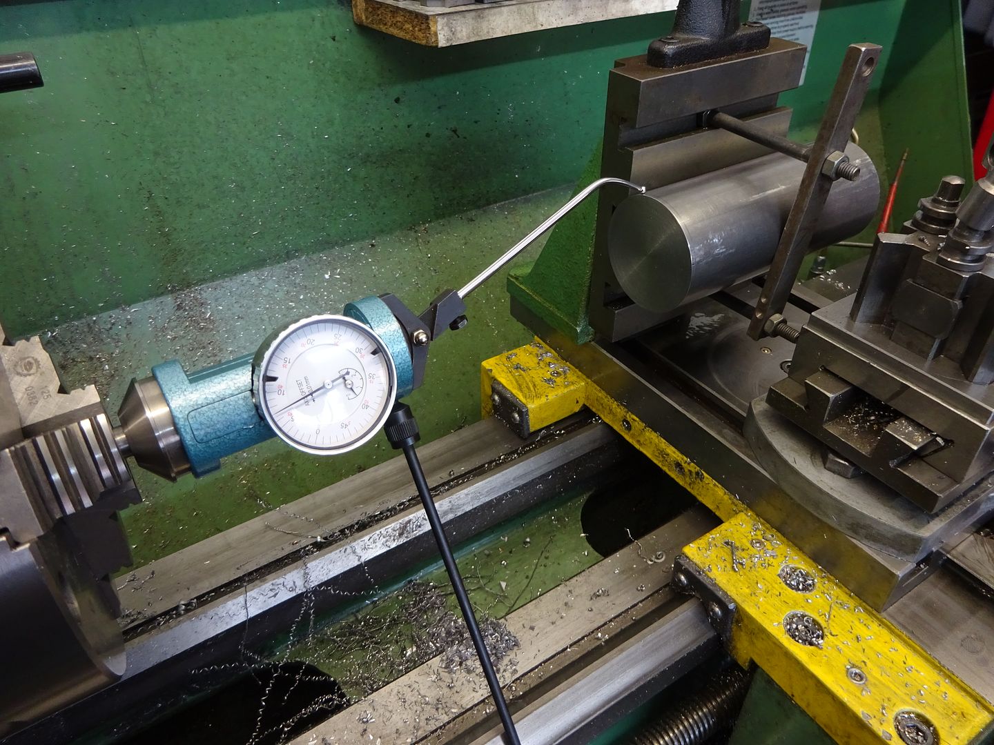
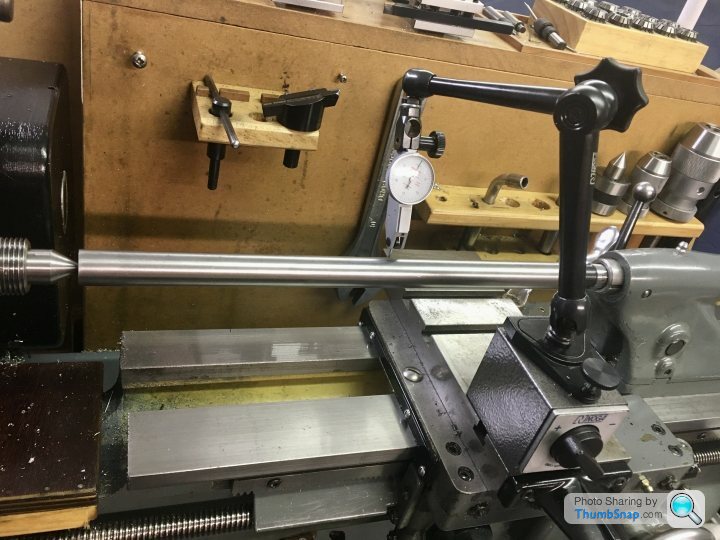
                            I made a start on the boring bar, by drilling the centres. I used the vertical slide method, although it was quite tricky. I put the bar in the 3-jaw chuck, and then offered the vertical slide up, making sure the bar seated in one of the slots. Once everything was clamped up I checked the top surface and side with a dti, and it was quite a way off in terms of not being parallel with the bed. I couldn't really get it right to the dti, yet it slid in and out of the chuck quite freely.

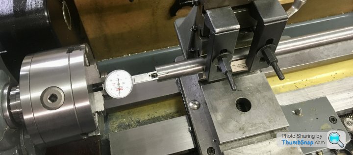
                            Anyway, I figured that the most important thing was concentricity with the chuck right at the end, so I fixed the dti in the jaws and got both ends to within 0.001" all the way around:

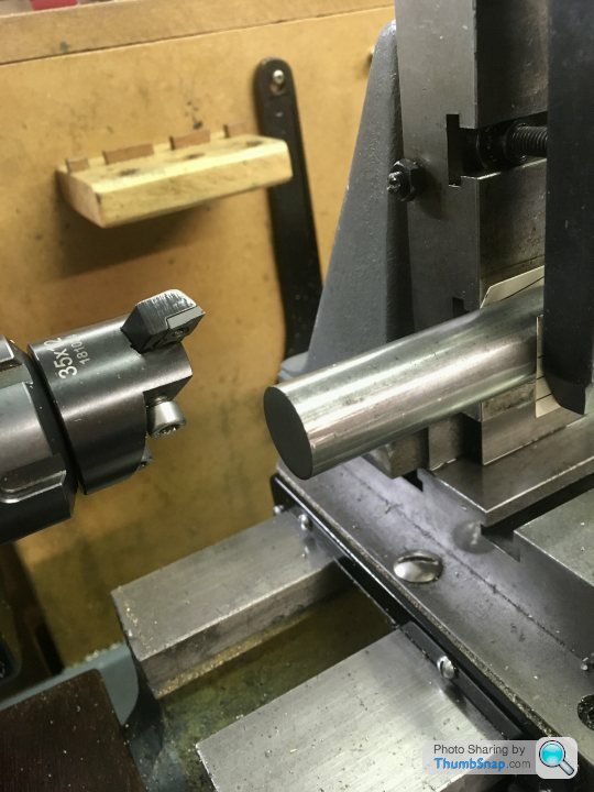
                            Then undid all that good work by fly cutting the end!

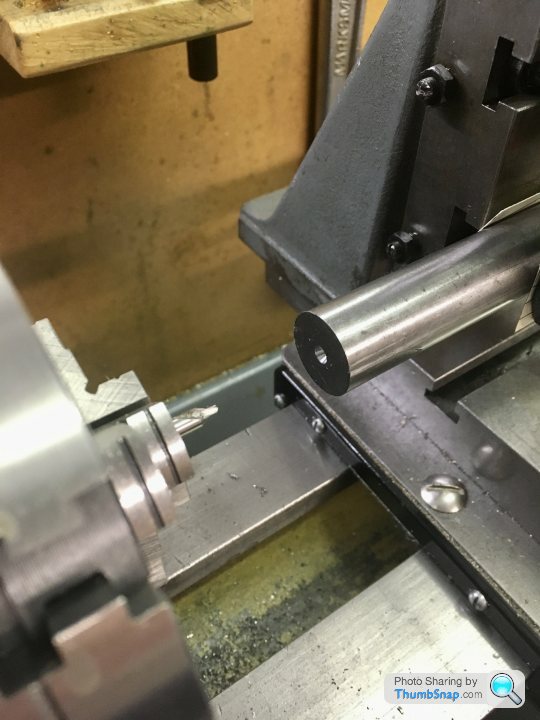
                            Then re-did the centering (I need to learn to think the order of things through more carefully), and centre drilled:

                            When both ends were done, I put the bar between centres. Side to side, on the top and side edges, I'm getting pretty much no deflection of the dti, but about 0.004" when I turn it on its axis:

                            I don't suppose it matters too much, since the cutter will be rotating around whatever virtual axis it has at that point, and it won't be moving axially anyway?

                            I could really do with making a proper holder for the dti in a chuck for these concentricity measurements, not sure if there's a simple plan out there – or I could 3D print something.

                            Assuming the above is OK, the next job will be to mill a flat for the carrier, and a flat for the grub screw hole, and to make the cutter hole. Then I think that's about it.

                            BTW, for the boring operation, I was thinking of fitting my old 3-jaw chuck over the live centre, and using the jaws to contact the carrier (if it fits). I think it would save me messing about with bits of wire to stop it flapping about?

                            #538040
                            Dr_GMJN
                            Participant
                              @dr_gmjn

                              I’ve been looking at a couple of past threads on boring bars, and some seem to suggest a diagonal hole for the tool is better – presumably to increase stiffness.

                              Before I cross-drill it (with an adjustment grub screw), is the diagonal method worth it? Is it a case of setting the bar at some angle in the vice and slot drilling to begin with?

                              Thanks.

                              #538048
                              JasonB
                              Moderator
                                @jasonb

                                The angled designs tend to mount the tool at a specific angle so that a screw can be used to advance the tool by a set amount per turn.

                                Never bothered myself and find the 90deg hole makes for easier tool grinding so all my homemade one sate 90deg, though the Micro bore head does have it's own scale so you know how much the tool is advanced but don't use that much.

                                #538222
                                Dr_GMJN
                                Participant
                                  @dr_gmjn
                                  Posted by Ramon Wilson on 11/11/2020 08:40:15:

                                  A simple pin set on centre line of the arc and another in the cylinder wall will locate the feet accurately enough while the JB sets, though I was underr the impression the mating area was going to be machined too.

                                  Yes another way this op can be done, but as Jason says it would be best to machine the lower surfaces after bonding – done with the cylinder held on a mandrel the dimension would be both identical over both parts and importantly parallel with the cylinder bore too

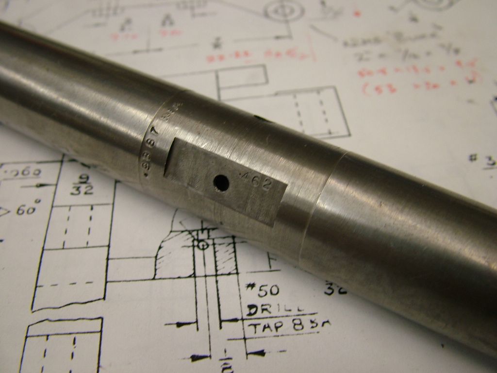
                                  You can make a simple 'tween centres boring bar of any size you want to suit the job. I have some made many years back from silver steel. They have a small flat on them where the cross hole for the 1/4 HSS cutter goes. By making the hole blind the flat area can be drilled and tapped for say a 6ba screw which helps move the cutter when very small movements are required. Remove screw, mic across flat and tool tip – simple maths gives the radius. There are other ways – inset adjustable carbide tips for instance but that above has served me well for a long time now – I much prefer to use 'between' centres for bores to eliminate taper.

                                  Soft solder will be sufficient!

                                  Ramon

                                  This pic should help explain it better. The turned portion is to ensure the diameter is true to the axis of the centres. Radius required is dimension plus .462 across tool tip and flat

                                  dscf0420.jpg

                                  Edited By Ramon Wilson on 11/11/2020 08:52:42

                                  I’m making the bar at the moment – what is the purpose of locally turning it true? I can see that it’ll give a co-axial cylinder where the tool is, but a

                                  I assumed you’d machine, measure and re-set the tool. I can’t figure out why you’d need a cylindrical portion of the bar?

                                  Also, I think I’ve cut the bar too long. Presumably it should be the minimum length for the job plus a bit – but how far each side should the ‘plus a bit’ be?

                                  Thanks.

                                  #538227
                                  JasonB
                                  Moderator
                                    @jasonb

                                    As you will need to set the tool to desired radius plus half the bar diameter turning the area around the hole true ensured that the half diameter is actually half diameter not what half the bar is from the lathe axis.

                                    I think mine have a length approx equal to the bar dia turned true equalised about the hole

                                    Edited By JasonB on 05/04/2021 19:14:40

                                    #538253
                                    Dr_GMJN
                                    Participant
                                      @dr_gmjn
                                      Posted by JasonB on 05/04/2021 19:13:13:

                                      As you will need to set the tool to desired radius plus half the bar diameter turning the area around the hole true ensured that the half diameter is actually half diameter not what half the bar is from the lathe axis.

                                      I think mine have a length approx equal to the bar dia turned true equalised about the hole

                                      Edited By JasonB on 05/04/2021 19:14:40

                                      Don’t you turn the bore until it cleans up, measure it, and increment the tool outwards by half the difference to final diameter? I can see why a flat would make tool extension measurement more accurate, but not how turning cylindrical would help, unless it’s for absolute rather than relative measurement?

                                      #538292
                                      JasonB
                                      Moderator
                                        @jasonb

                                        You can do it either way but having the section of bar true to the axis means it's there ready to make use of, also some of my bars are from quite rough hot rolled material so you would be measuring on an uneven surface which won't be very consistent.

                                        As for overlength bar I sometimes drive with the chuck and just support the tailstock end with the ctr so you can put more of the bar into the chuck if it's too long but it does save having to keep making bars when the next longer job comes along.

                                        #538412
                                        Dr_GMJN
                                        Participant
                                          @dr_gmjn
                                          Posted by JasonB on 06/04/2021 07:46:25:

                                          You can do it either way but having the section of bar true to the axis means it's there ready to make use of, also some of my bars are from quite rough hot rolled material so you would be measuring on an uneven surface which won't be very consistent.

                                          As for overlength bar I sometimes drive with the chuck and just support the tailstock end with the ctr so you can put more of the bar into the chuck if it's too long but it does save having to keep making bars when the next longer job comes along.

                                          Ok understood, thanks.

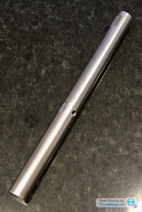
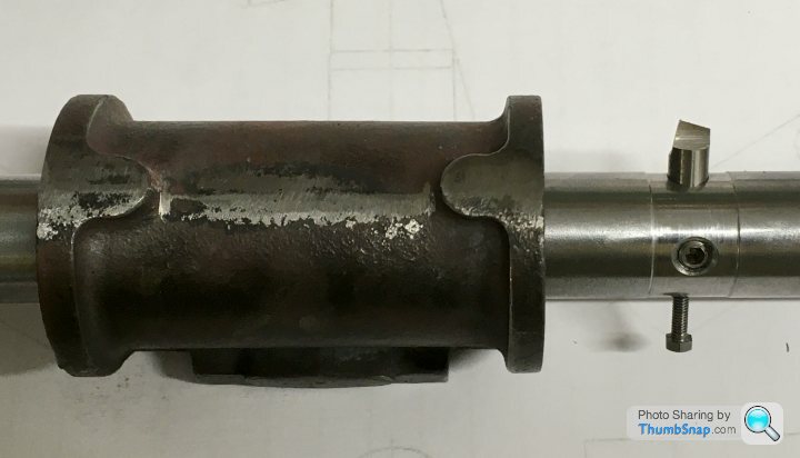
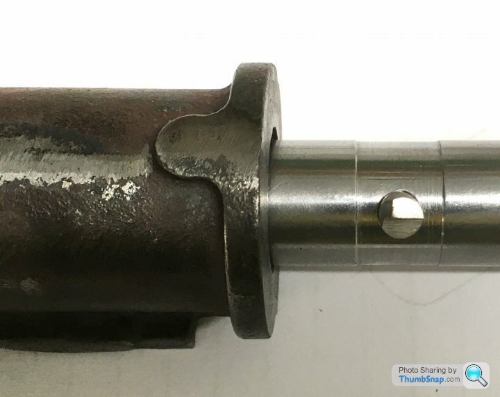
                                          So this is the first attempt. I did shorten it a bit – I can't see doing anything longer than the P.R. cylinders, and wanted to maximise stiffness. I've still got a couple of inches each side of the cylinder to play with:

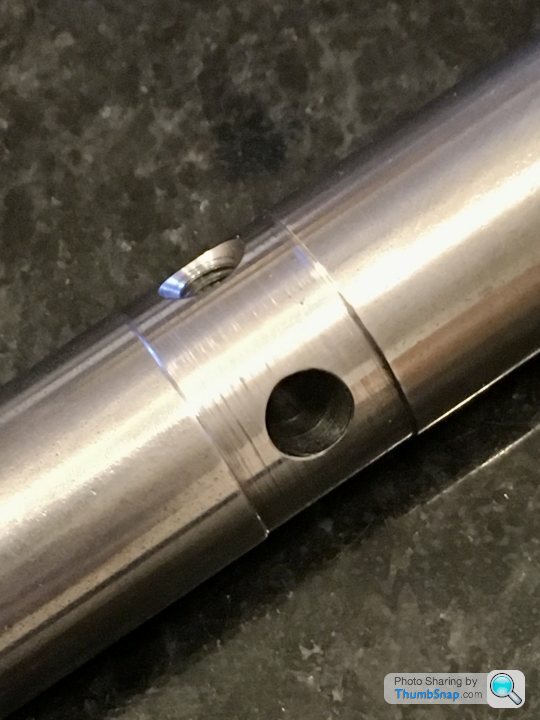
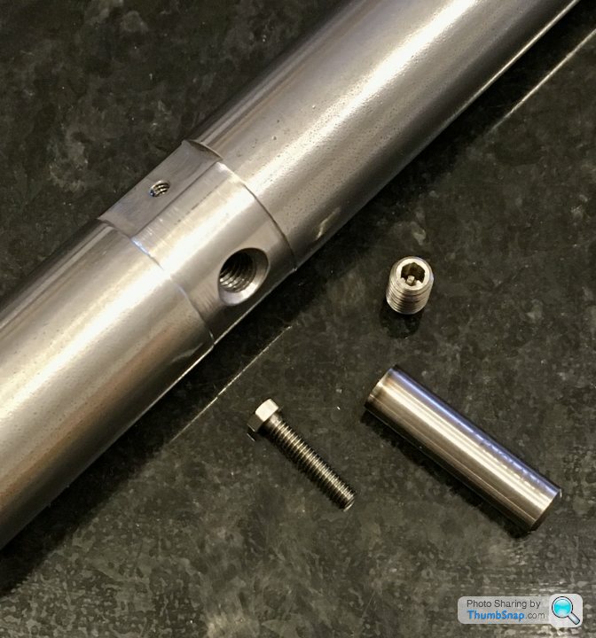
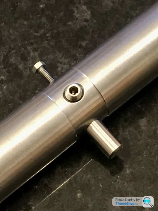
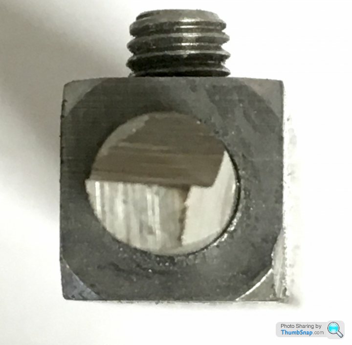
                                          I didn't have a 6BA tap, so used 7BA for the adjusting screw instead. The locking grub screw is M5 – might need turning down a bit because I think it will touch the bore as it is. The tool hole is drilled at 6mm, and the spare stubs that Ramon sent me are a snug fit in it. The adjuster thread is 4mm long, the tool bore 14mm long. I did turn the middle true – it wasn't really out at all, and I'm not particularly proud of the finish I got, but I don't suppose it matters. Also milled the flat for measuring, and another for the carrier:

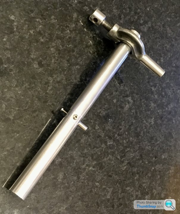
                                          I also found a 3/4" carrier in a box of stuff I got with the lathe, which cleaned up nicely. If it doesn't work at least I've got a nice steam punk hammer:

                                          Now to grind a few tool bits. I'm wondering if I should make a grinding holder for them out of perhaps square bar – I think holding by hand isn't really on, and grips might burr the surface such that it might not fit in its socket?

                                          #539135
                                          Dr_GMJN
                                          Participant
                                            @dr_gmjn

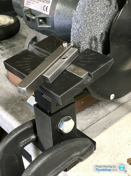
                                            So I 3D printed a grinding jig, which I temporarily fitted in front of the bench grinder. I've graduated the angle markers at 10 degrees (they still need filling with white Milliput), and I'm hoping absolute accuracy isn't essential for this:

                                            Is it acceptable to use the side of the wheel for grinding? If not, I think I need to make another recess in the table 90 degrees to the existing one.

                                            Also made a holder for the 6mm diameter bits that Ramon sent me – my fingers were getting burned without it:

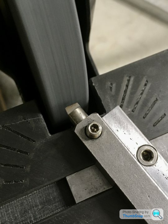
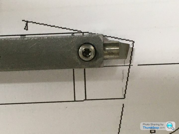
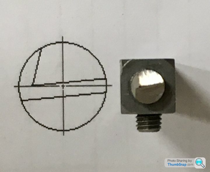
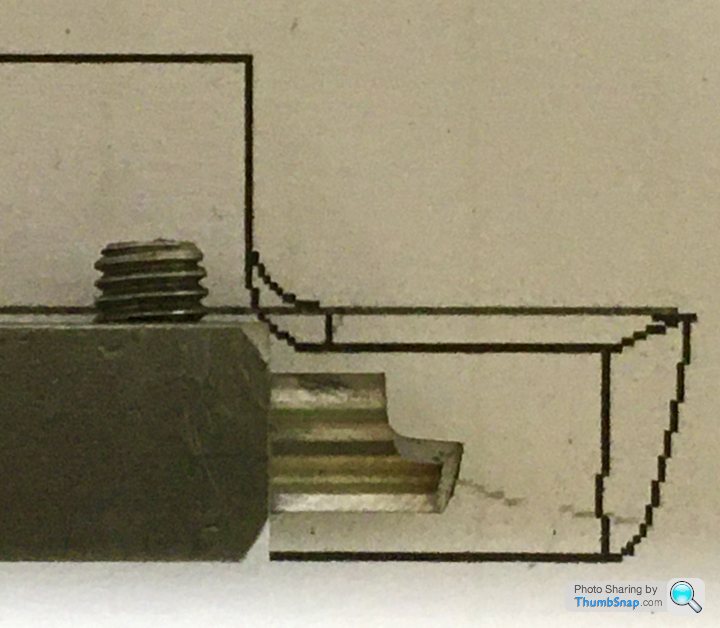
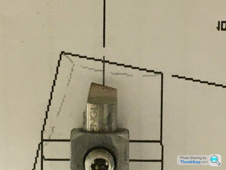
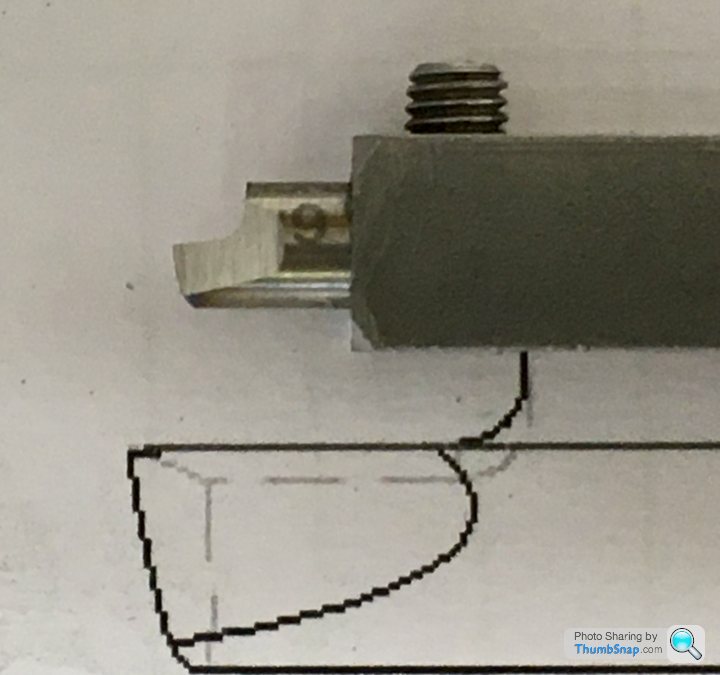
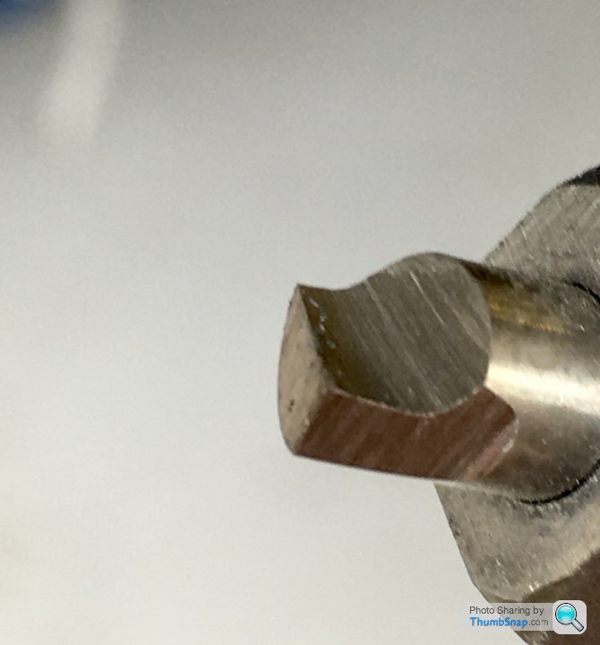
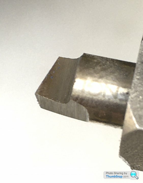
                                            I have followed Jason's diagrams, but I'd like some comments on accuracy, surface finish, whether it needs a tip radius, whether it needs further finishing with the diamond files, or anything else that's relevant. I've never ground tools before, and don't want to ruin a casting through not grinding the them accurately enough. Here is where I am:

                                            Have I ground this in the right orientation? The intention was to set up as shown, and move the cylinder on the cross slide from left to right (chuck would be on the left of these images:

                                            I'm not even sure how the tool should be orientated in the bar, and which surfaces are is doing the cutting! Does centre height setting apply to this method, if so, how to you adjust it? As I said, any and all advice gratefully received.

                                            Thanks.

                                            Edited By Dr_GMJN on 11/04/2021 13:10:51

                                            #539155
                                            JasonB
                                            Moderator
                                              @jasonb

                                              Looks about right.

                                              Just make sure that the bottom of the tool arrowed in blue does not rub against the edge of the hole

                                              docs tool.jpg

                                              Its the arrowed edge that does the cutting and that's the one you could give a run to with a diamond slip

                                              docs tool 2.jpg

                                              Best to avoid using teh side of teh wheel if you can

                                              #539176
                                              Dr_GMJN
                                              Participant
                                                @dr_gmjn

                                                OK thanks Jason.

                                                So I'll make a couple more for good luck, touch the edge up with the diamond file, and also grind them to the correct length.

                                                On the last photo I posted, should the tool be rotated anti-clockwise slightly? I noticed the flat behind the cutting edge was angled down in the grinding drawing, but obviously you can orientate it how you want in the bar.

                                                Just got to do some car work this week, then I can finally make a start on this one.

                                                #539179
                                                JasonB
                                                Moderator
                                                  @jasonb

                                                  Yes you want the top face sloping down slightly from the cutting edge as shown in green but make sure the red clearance angle is not lost as you rotate it, you want both to be about 5degrees

                                                  docs tool 3.jpg

                                                  #539225
                                                  Dr_GMJN
                                                  Participant
                                                    @dr_gmjn

                                                    OK.

                                                    when filing the edges, am I aiming for a sharp angle, with no edge or tip radius at all?

                                                    Also, how long will the bit stay sharp? Should I re-file it after every cut, or perhaps before the final couple of cuts?

                                                    Thanks.

                                                    #539269
                                                    JasonB
                                                    Moderator
                                                      @jasonb

                                                      I don't round mine.

                                                      Yes once you are close give it a lick with the diamond so it's good and sharp for the last couple of cuts.

                                                    Viewing 25 posts - 126 through 150 (of 1,206 total)
                                                    • Please log in to reply to this topic. Registering is free and easy using the links on the menu at the top of this page.

                                                    Advert

                                                    Latest Replies

                                                    Viewing 25 topics - 1 through 25 (of 25 total)
                                                    Viewing 25 topics - 1 through 25 (of 25 total)

                                                    View full reply list.

                                                    Advert

                                                    Newsletter Sign-up