Stuart Twin Victoria (Princess Royal) Mill Engine

Advert

Stuart Twin Victoria (Princess Royal) Mill Engine

Home Forums Work In Progress and completed items Stuart Twin Victoria (Princess Royal) Mill Engine

Viewing 25 posts - 1,101 through 1,125 (of 1,206 total)
  • Author
    Posts
  • #651670
    JasonB
    Moderator
      @jasonb

      I mostly tend to do mine from one piece

      Half way down the page there are some photos showing the steps to get the belly shape.

      On the James Coombes I did recently I used a 0.8mm radius insert which I think you should have. The Unreal I did with a 1mm radius insert which is not a lot larger

      Advert
      #651726
      Ramon Wilson
      Participant
        @ramonwilson3

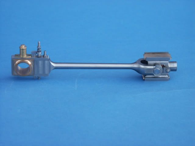
        Yes, there's nothing wrong with making them from solid just that it requires more material and a lot more machining. A mistake somewhere along the way means a likely restart and obviously more material. The further you get into the machining the more there is to lose. The Corliss con rod came out of one piece as did the marine engine rods.

        The double diagonal rods were different to each other and much shorter that average but fish bellied and took quite some machiningdscf1277.jpg

        It was a big step back when I realised this one was a scrapper though sad

        dscf1292.jpg

        As always Doc it's down to choice – good luck with them however you go about it

        #651911
        Dr_GMJN
        Participant
          @dr_gmjn

          I like the idea of fish-bellied rods rather than straight-tapered, so hopefully I’ll end up with something like Ramon’s engine.

          Id like to stick with machined from solid, but where do you fit the carrier if machining between centres? Do you clamp the carrier around the faceplate end, and constantly swap the workpiece as you turn the tapers, hopefully not damaging anything?

          Presumably the tapers are done by re-setting the topslide rather than offsetting the tailstock?

          Is it a question of marking the start and end of the tapers with a marker and working to scribed lines, then swapping the ends and repeating the cuts?

          I think I’ll use the parallel middle and two angled cut method (5 facets in total per rod) then smooth them. I will have to do a drawing to get the marking out right.

          Thanks.

          #651942
          JasonB
          Moderator
            @jasonb

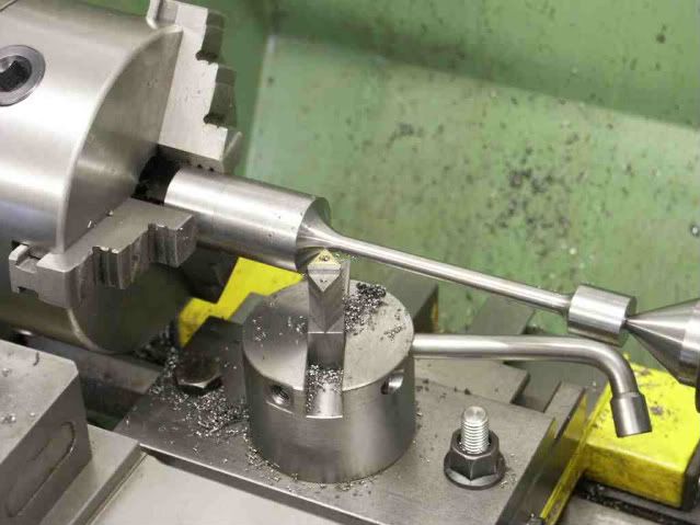
            Doc if you follow the links I posted at the bottom of the previous page to the Real in particular and James Coombes you will see that I don't use a carrier, I mark with a Sharpie.

            The three facets that I show is more than adequate for these small rods and the angles involved See the other thread linked to

            To save upsetting the tailstock I sometimes use my boring head to offset for the tapers but as they are not that long and you will end up hand finishing then the topslide is fine and it's what I used on the Real which is exactly the same as the Victoria part

            You will also see that I have excess material at each end that can be used to clamp a drive dog to or simply hold in a chuck so no risk of marking a finished surface or having ctr holes where you don't want them


            Edited By JasonB on 13/07/2023 07:10:51

            #652040
            Dr_GMJN
            Participant
              @dr_gmjn

              Thanks Jason, yes I saw the links now.

              So as far as I can see the procedure would be:

              1) Mill my square stock to the rectangular section of the largest end (the stock I have is oversized).

              2) Cut to overall length + c.10mm on each end.

              3) Put in 4-jaw, centre drill one end, and extend it out of the chuck to be supported by the tailstock.

              4) Mark out the ends of the radii at each end of the round section.

              Not sure from here, because I can't figure out how to simultaneously turn the end blend radii to be the right diameter and to the right run-out length at the rectangular bosses. I can't turn to diameter first, because if it ends up being too far away from the end, I'll have a parallel section rather than a taper blending to a radius.

              I'm going to get an 8mm diameter button tool for the radii, because I like the look of a larger radius there.

              Thanks.

              #652047
              JasonB
              Moderator
                @jasonb

                1 You really only need to mill the ends to their rectangular shape

                2. Put the holes and slot for the fork in while you still have 4 sides to hold in the vice which make sit easy to do in the mill

                3 Cut, face and ctr

                4 You can scribe a line where the big end rectangular section ends. Likewise the extend of the forked end's "U" shape can be marked by scribing around a disc or bar end.

                5 Turn parallel between the marks to the fattest diameter of your belly

                6 Cad will give you angles to end up with the desired waist diameter at each end but probably easier to set the topslide over to a larger angle than needed. Turn the taper working into an end and see how far along the rod it feathers out once you have got the desired waist diameter, adjust angle of topslide and cut again until it runs out at 1/3rd distance

                4mm radius sounds quite large for that size rod, you may get an odd looking side to the big end rectangles and chatter risk goes up. I don't often use anything more than 1.5mm radius on rods, on the odd occasion I have needed bigger it's been a lot and I used a ball turner

                #652052
                JasonB
                Moderator
                  @jasonb

                  Oh I just looked at the PR drawings and it is not a fish belly that is fatter in the middle as the diameters at each end are different, and it'd not forked at the end like the Victoria.

                  Bending the stock by rigidly holding the big end and offsetting the small end and then using the carriage power feed will give the classic taper or "entasis" but again by just turning a taper just over half way along and then blending with the file will give a very close representation. See the short leg of the "tee" shaped one on the James Coombes

                  #652072
                  Dr_GMJN
                  Participant
                    @dr_gmjn

                    Thanks Jason. The PR drawings call for a 5/32" radius at each end (about 3.97mm).

                    Yes, the drawings show a straight-taper rod, but I would like to change this to a fish bellied type, as per Ramon's model.

                    #652110
                    JasonB
                    Moderator
                      @jasonb

                      Bear in mind that Ramon's Twin Vic and mine were for the forked end rods where the waist is the same diameter at each end, you have differing diameters on PR so the belly needs to be done differently

                      #652286
                      Dr_GMJN
                      Participant
                        @dr_gmjn

                        Hmm it looks like a 4mm radius at the ends is a minimum in order to get a nice blend without the corners of the bosses being slightly concave with pointy corners (I want the blends to run out over all four faces of each end rather the being a small fillet against rectangular faces.

                        #652287
                        JasonB
                        Moderator
                          @jasonb

                          Whatever radius you use it should not end up concave (undercut) as you feed in with the cross slide which is 90deg across the lathe

                          #652295
                          Dr_GMJN
                          Participant
                            @dr_gmjn
                            Posted by JasonB on 14/07/2023 16:36:34:

                            Whatever radius you use it should not end up concave (undercut) as you feed in with the cross slide which is 90deg across the lathe

                            Yes I guess so. TBH I’m still puzzling over how to get length and diameter both correct and equal on both rods. The tapers have no straight line definition of where the radius runs out.

                            If I turn to the right small diameter, but the length is wrong, I’d then have to move along into the ends (potentially giving the concave geometry, then out sideways to get rid of that, but that would then change the radius run-out length on the blocks.

                            Im thinking find the centre of the rod by measuring from one end, then turn the whole circular length to the maximum central O/D, then mark the beginning of the taper onto an area of felt-tipped pen, set the topslide to the correct angle and turn up to the marked lines, then set topslide extension (hoping that by the ends, everything is right and runs out to the blocks.

                            All that would rely on setting lengths to the drawing, and hoping I can accurately set the topslide to a very specific angle.

                            #652299
                            JasonB
                            Moderator
                              @jasonb

                              As I said start from the shoulders and work into the middle increasing the angle until you hit the sharpie line. You do not need micron accuracy as to where the taper meets the mid section, after all you will only be blending by hand with a file and using your eye to judge what looks right.

                              You have CAD so should easily be able to work out offsets and infeed if you feel you need them, though I tend to just work to a light scriber mark on one side of the rectangular portion. Just make a note of any handwheel readings for the first one and then repeat for the second.

                              As I have said a few times the fat part of the belly won't be mid rod as diameters at each end are different. Think of it as a long harrow ellipse if you slice off one end at 1/4" and the other at 5/16" your slice lines will be different dimensions from the mid point.

                              #652304
                              Dr_GMJN
                              Participant
                                @dr_gmjn

                                Sorry Jason I don’t fully understand:

                                If I start at a shoulder and feed in with a button tool, I’m simultaneously reducing diameter and shortening the rectangular bit. Aren’t the chances of hitting the line, and the correct diameter at the same time pretty slim?

                                Ive CADed up a fish bellied design, and made the lengths to the blend centres equal. Why would the diameters be different at each end? After all, I’m defining them as the same. The blocks are different sizes, but the blends run into and out of them however they need to.

                                #652313
                                JasonB
                                Moderator
                                  @jasonb

                                  Its a case of playing with the hand wheels to avoid cutting into the rectangle as you feed in. In practice you start a little away from the shoulder feed in then move to the shoulder and then along the taper.

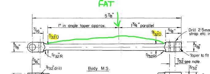
                                  Different diameters on the Princess royal drawing due to him using a chunkier big end. To get the look of entasis just blend the parallel section with the 1deg taper which is the preferable "look". To do a fish belly if that is what you want make the fat part where I have indicated otherwise the rod may look a bit spindly where it joins the big end

                                  pr rod.jpg

                                  #652387
                                  Dr_GMJN
                                  Participant
                                    @dr_gmjn

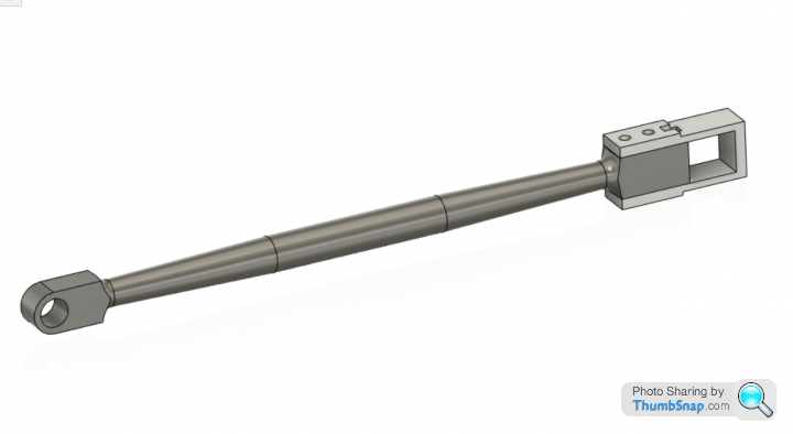
                                    OK this is the best compromise I can make for a symmetrical fish-bellied rod. No blend filing shown. It's a 3 degree overall taper at each end (topslide set to 1.5 degrees).

                                    It doesn't look terrible, but overall think I'll abandon that and stick with what's in the plan. It's just that the plan version seemed such a subtle shape that it didn't suggest any real strength benefit over a straight rod.

                                    #652393
                                    Dr_GMJN
                                    Participant
                                      @dr_gmjn

                                      Got the taper pins and reamer. Then, while figuring out how to hold the forks and shaft for drilling, found an issue: For some reason years ago I changed the four hole offsets for the slide bars to be further out. I think I might have done this becasue as drawn, the round mounting pillars overhang the inner base walls a bit, and moving the holes makes them look much better.

                                      The result of this is that the overall width of the fork and brass block assemblies needed adjusting by the same amount (about 0.9mm per side). This, I didn't do:

                                      I don't want to offest the sliders, becasue the mounting nuts wouldn't be central.

                                      I could make spacers to pack out the brass sliders, 0.9 mm wide. Since I can't find any images of a real engine having shims or spacers, I'm not really happy to do that.

                                      Seems the only remaining options are:

                                      1) Add (solder or screw) 1mm thick face plates to the outer faces of the brass blocks and re-machine them to match the existing block thicknesses (difficult to set up to make everything square again I guess). Would also require significantly wider slide bars.

                                      2) Solder bosses to the forks (probably look rubbish due to the imperfect concentricity of the turned bosses to the end radii).

                                      3) Make 4 new brass blocks.

                                      4) Make 2 new forks.

                                      I'm erring towards re-making the forks, since as I mentioned before, more substantial bosses would look much better, and I could mill them at the same time as the end radii using the R/T.

                                      All this is a direct result of the fragmented timeline of building this model; I'd forgotten to note it on the slider drawings when I modified the base drawings.

                                      I've got a day off on Monday, so hopefully I can get the new parts made.

                                      #703198
                                      Dr_GMJN
                                      Participant
                                        @dr_gmjn

                                        Happy New Year to everyone – I’ve not given up on this one, just waiting for some motivation to start the forks again, and for the workshop to warm up a bit. Ill be back…

                                        #703223
                                        Ramon Wilson
                                        Participant
                                          @ramonwilson3

                                          Happy New Year to you too Doc, I’m in much the same situation but have had some good time on the plastic😉

                                          Re the forks – why not bore them out slightly and make two top hat bushes to Loctite in – chamfer the holes in the fork so they face up really tight and you’ll hardly notice it once some oil is on. They’ll look like bosses that are meant to be there – big save timewise if you do

                                          All the best – R

                                          #703462
                                          Dr_GMJN
                                          Participant
                                            @dr_gmjn

                                            Ramon, I’ve got four models on the bench at the moment, some have been there for over two years. I’m trying to clear them, then get back to having one ME project, and one plastic project!

                                            I like the idea of the top-hat repair. I’m going to the garage in a minute to get some paint on a Spitfire, so I’ll have a quick look.

                                            Cheers!

                                            #703510
                                            Ramon Wilson
                                            Participant
                                              @ramonwilson3

                                              Hi Doc, yes I share the situation. I did finish the Phantom and a F-100F though that still requires a base but there are others that await attention along with the marine engine of course – don’t see much happening on that however until the Autumn.

                                              I have made big changes in the workshop and just starting the last phase in creating a clean space for displaying so once that is finalised I should be able to give it more attention but physically I am really slowing down – no where near the output of the past I’m afraid so sights are set much lower these days though the ‘stash’ seems to grow exponentially.

                                              Enjoy your modelling where ever it takes you – R


                                              PS are you close enough to go to the Peterborough show in March?


                                              #704075
                                              Dr_GMJN
                                              Participant
                                                @dr_gmjn

                                                Ramon, no Peterborough is a bit too far from Sheffield. Next IPMS show for me is Leeds at the Royal Armouries in February.

                                                I am on with a 1:72 Spitfire at the moment (started as a Christmas project on 2022!). I also decided to make a model building stand – own design, 3D printed. I was a bit skeptical about them, but since finishing it on Sunday, I’ve used it a lot:

                                                5QRaS2ru

                                                This was the previous version “made” by my son for me many years ago – it’s actually seen a lot of use, and I still use it for larger models like the Vulcan (still unfinished since Christmas 2021!):


                                                IMG_4940


                                                Re. the top hat bush idea – I might have a go at that, but would solder instead of Loctite possibly make the joint less obvious if there were any slight discrepancies in fit around the join?

                                                #707138
                                                Dr_GMJN
                                                Participant
                                                  @dr_gmjn

                                                  Despite it being pretty cold in the garage, I’m getting itchy fingers again to progress with this one. Too much plastic modelling recently, and it’s bad to get demoralised by daft setbacks like this was.

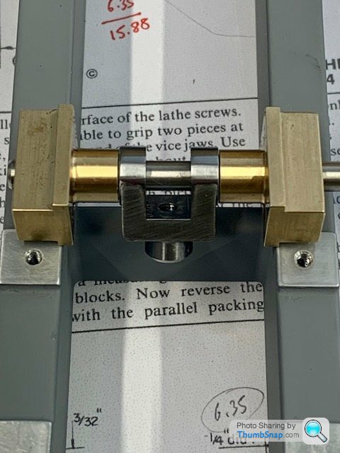
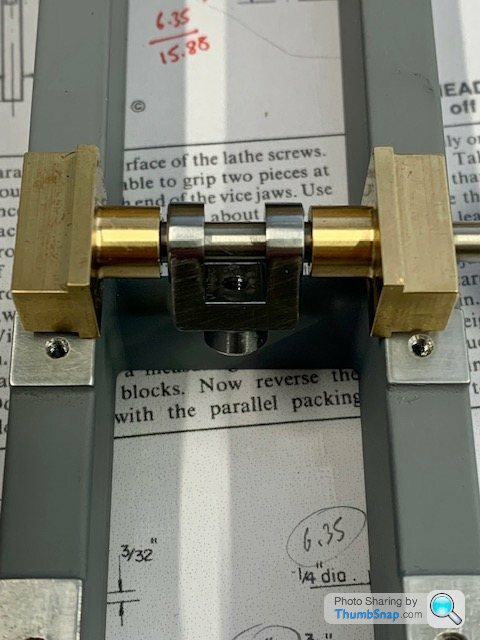
                                                  Briefly, I’d previously slightly modified the spacing between the crosshead slides, but forgot to widen the forks to suit. Result is a gap between the brasssliders and the forks, approx 1 mm per side:

                                                  IMG_5180

                                                  Further to Ramon’s suggestion of rescuing the too narrow forked ends with top-hat bushes, I drew up this today.

                                                  The idea is to make 4 bushes. The stub diameter is 6.5mm since I have a 6.5mm slot drill.

                                                  I would set up each fork on an expanding mandrel/bolt in a collet so that one side of the fork is held concentric, then use a slot drill in the tailstock to bore a locating hole in the outer fork. I’d eventually repeat this on all four prongs – obviously I’d need two diameters of mandrel.

                                                  I’d then make 4 top-hat bushes, with their flanges oversized. I’d make these a tight press-fit into the forks, and solder them in place.

                                                  Then I’d use a lathe tool with a 0.3mm tip radius to machine the flanges to match the adjoining brass slider boss diameters.

                                                  I’d re-ream them to 5mm sequentially, so that once one fork prong was bushed, the opposite existing, unmodified, 5mm hole would guide the reamer into the opposite repair bush which had been drilled to pre-ream size. Then repeat when the opposite bush was fitted.

                                                  Then I’d face the new bushes to the correct width.

                                                  Hopefully the joint would not be too visible.

                                                  Any thoughts? Should I just start again, re-make the forks and be done with it? Re-make the brass sliders with extended bosses? I’m not fussed either way at this stage, so long as it’s right in the end.


                                                  IMG_5179

                                                  IMG_5177

                                                  IMG_5178

                                                  #707174
                                                  Ramon Wilson
                                                  Participant
                                                    @ramonwilson3

                                                    Hello doc, Happy New Year to you.


                                                    I missed your last post – looks like were are in the same situation – Leeds is to far for me too – one day somewhere else perhaps?

                                                    Re the forks – it will be much quicker to make and fit the bushes which will save the forks. I would use Loctite personally but soldering would do too – a solder witness will go black after a time though. If they don’t end up satisfactory then time lost before making new ones is minimal

                                                    As you are going to bore each side out independently I would make the bushes so that they can be re-drilled and reamed in line after they are firmly in place to ensure all is in line.

                                                    My workshop renovation is near complete so I am back on the plastic this week currently a Revell 1/32 He 219 night fighter.

                                                    I like your build stand 👍 – mine are much more basic using contiboard and balsa wood 🙄

                                                    Best – R


                                                    #707286
                                                    Dr_GMJN
                                                    Participant
                                                      @dr_gmjn

                                                      Thanks Ramon. I will use Loctite and see how it goes.


                                                    Viewing 25 posts - 1,101 through 1,125 (of 1,206 total)
                                                    • Please log in to reply to this topic. Registering is free and easy using the links on the menu at the top of this page.

                                                    Advert

                                                    Latest Replies

                                                    Viewing 25 topics - 1 through 25 (of 25 total)
                                                    Viewing 25 topics - 1 through 25 (of 25 total)

                                                    View full reply list.

                                                    Advert

                                                    Newsletter Sign-up