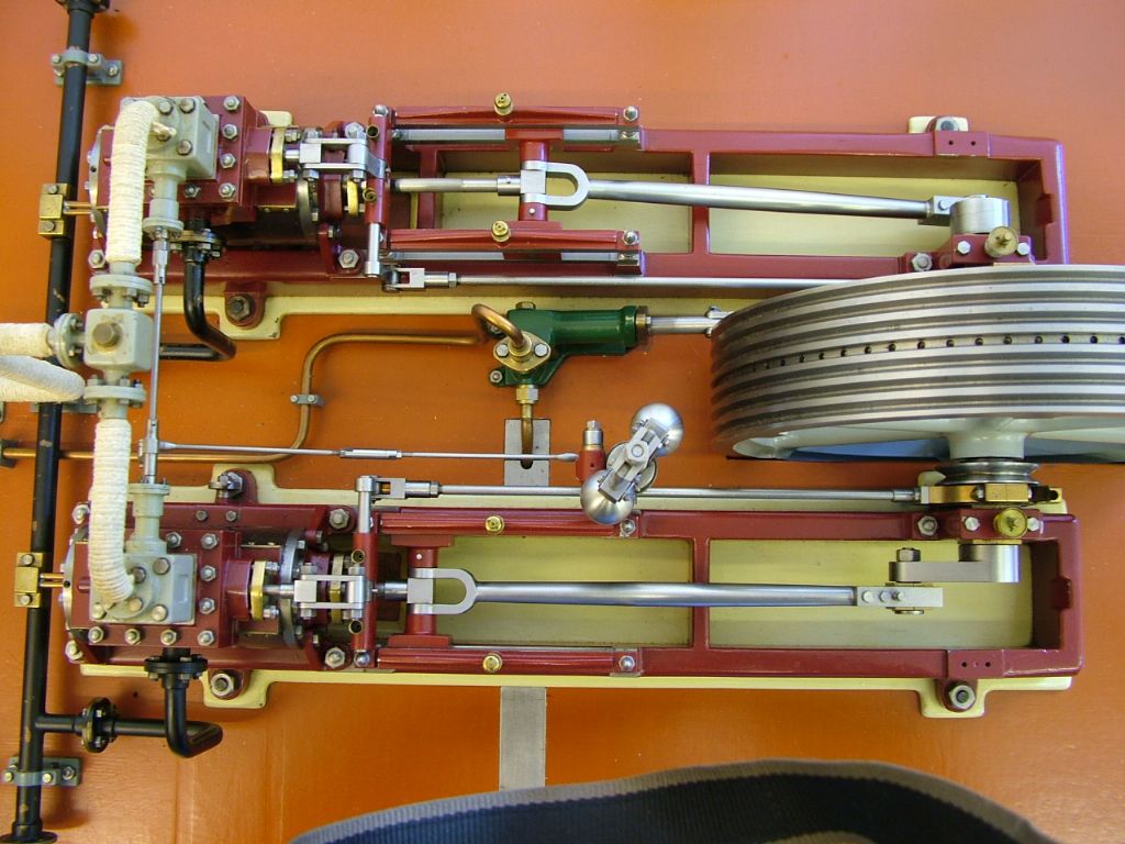
Stuart Twin Victoria (Princess Royal) Mill Engine

Advert

Stuart Twin Victoria (Princess Royal) Mill Engine

Home Forums Work In Progress and completed items Stuart Twin Victoria (Princess Royal) Mill Engine

Viewing 25 posts - 1,076 through 1,100 (of 1,206 total)
  • Author
    Posts
  • #651027
    JasonB
    Moderator
      @jasonb

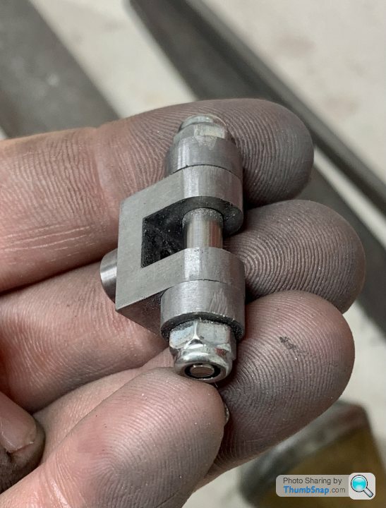
      Rounding over would be quite common in which case a taper pin would look better than a threaded hole to lock the pin. Forming a boss on the sides would also not be out of place.

      Advert
      #651036
      Martin Connelly
      Participant
        @martinconnelly55370

        I see from one of your pictures from 21 June that you have a 4 pin ER nut wrench. I cannot tell from your photos if the nut is one with a bearing or not. If you have milling cutters in an ER collet being pulled out there are a number of things that I would recommend, one is the 4 pin wrench which you have, another is a collet nut with an internal bearing and a third is that the inside taper of the collet chuck should be clean but with a fine smear of oil to allow the collet to close up easily. The tool shank and bore of the collets should be oil free and the collet slots clear of debris. The recommended torque for ER nuts is quite high and the best way to achieve this is with the bearing nut tightened with the 4 pin wrench and a correctly sized single ended wrench to suit the flats on the collet chuck. If you have a collet chuck without flats (there are some about) then spin up the grinder and put some on it. I, and I expect many people, have never had a milling cutter pull out of an ER chuck when using it following these recommendations.

        Martin C

        #651059
        JasonB
        Moderator
          @jasonb

          From other threads I think it was the head pulling down not the cutter.

          As you seem to get a better finish along the X axis then might be worth just turning the work around rather than do a Joe Pie and tackle all 5 in one go. What works on his bridgeport may not on a benchtop hobby mill.

          #651106
          Dr_GMJN
          Participant
            @dr_gmjn

            Thanks both.

            The tool didn’t move in the collet, nor the workpiece in the vice. After it grabbed, and damaged the vice, I was able to continue with much smaller cut depths. The thing is, if you look carefully at the witness mark (which leads to the cut in the vice) it’s a significant depth and distance that the tool dragged itself along. Seems like a load of deflection must have occurred if that was the case.

            Re. the forked ends: I think I’ll go with rounding them, and some small chamfers on the boss and shoulders. I can’t make the raised cheek plates without thinning the forks, and I’d rather not do that.

            I understand if rounded, the locking bolt hole would be right on the tangent line and wouldn’t look great. Do the taper pins fit in parallel drilled or reamed holes? If I do this, are they drilled with the rods in place? My intention was to drill and ream the forks to 3/16” (as I did with the brass sliders). If this is the case, what’s the best way of holding the rod in place while doing these operations? Do the taper pins have nuts to draw them in (like on the connecting rod crank end adjustment)? If you just tap them in with a hammer and drift, is there a risk of damaging something on assembly (e.g. the slide bars), and how do you disassemble them?

            Thanks.

            #651108
            JasonB
            Moderator
              @jasonb

              The one in the photo is a 1/16" taper pin – 1/16" at it's largest point tapering at 1:48 for which a taper pin reamer has to be used. Depending on the length you would drill the assembled parts 1.4mm and then ream the hole with care.

              Much like a morse taper the pins are self locking are gently tapped in with a hammer and need drifting out from the other end to remove. A bit of creative clamping allows the two parts to be drilled as one.

              You could actually assemble the conrod, fork and 3/16" pin off of the engine place onto the lower slide bars, add the top ones and then fir piston rod and the other end of the conrod.

              #651110
              Martin Connelly
              Participant
                @martinconnelly55370

                The taper pins lock in the same way a Morse taper does. They do not need a lot of hammering to put them in place or to remove them but they stay in place under normal circumstances. I think the imperial taper is 1:48 and the metric equivalent is 1:50. You need a taper reamer to suit your preference and you can buy tapered pins to cut to size. There are plenty of examples of machine tools with handles held in position by taper pins.

                Martin C

                Jason typed faster than me

                Edited By Martin Connelly on 05/07/2023 20:32:18

                #651119
                Dr_GMJN
                Participant
                  @dr_gmjn

                  Thanks both, I think I’ll get a pin a screamer and do it that way then. I don’t have the plans to hand, but I’m wondering if I can use the same reamer for the crank pin bearing.

                  #651139
                  Dr_GMJN
                  Participant
                    @dr_gmjn
                    Posted by Dr_GMJN on 05/07/2023 21:44:06:

                    Thanks both, I think I’ll get a pin a screamer and do it that way then. I don’t have the plans to hand, but I’m wondering if I can use the same reamer for the crank pin bearing.

                    Hmmm autocorrect!

                    * taper pin and reamer.

                    #651140
                    JasonB
                    Moderator
                      @jasonb

                      Do some practice ones first, at that size the reamers are very delicate and there is a lot of engagement.

                      Hold the pin against the job and measure the diameter where it will exit and drill right through that size say it's 1.4mm, then go half way with a 1.5 so there is a minimum of material for the reamer to remove.

                      #651141
                      Martin Connelly
                      Participant
                        @martinconnelly55370

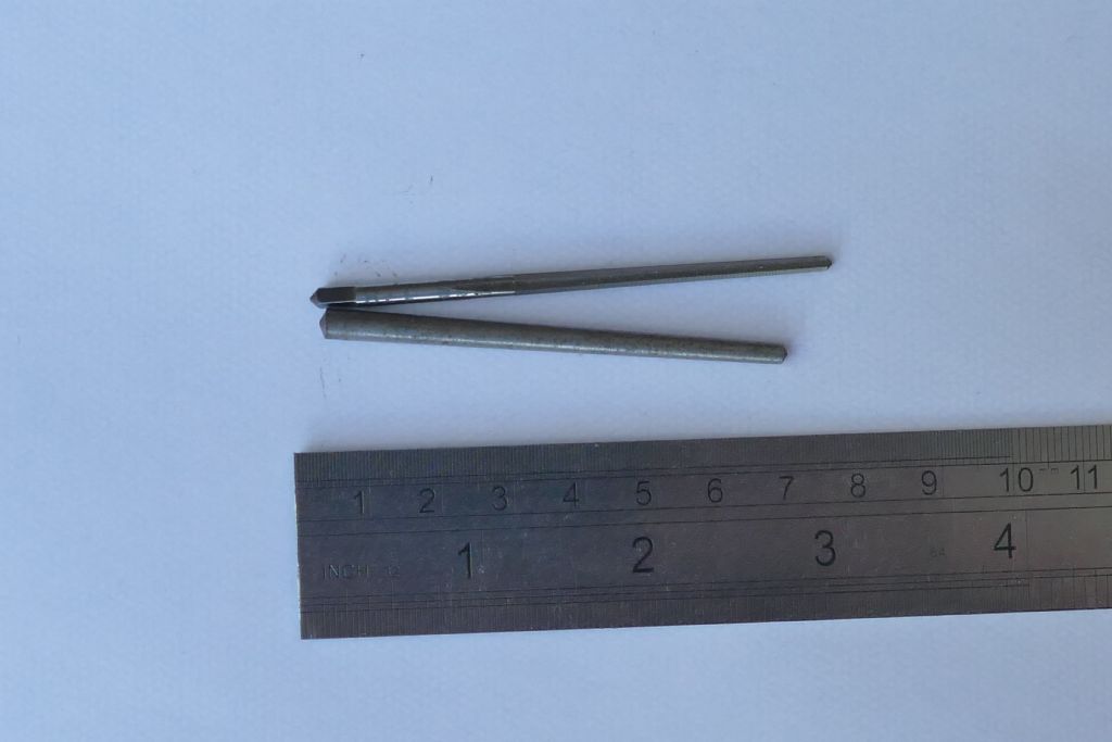
                        This is a taper reamer, size is 1/8" so it is 1:48 taper with the 1/8" being the larger end. The cutting length is about 2" so you can work out that the other end goes down to about 3/32". The pin is a 3/16" pin and goes from 3/16" to 1/8" so they do not match, I would need a smaller pin or a larger reamer depending on what I was going to be doing. The larger pin suits the existing taper pin holes on my lathe which is why I have it, the reamer was just the first one I picked up but thought the differences in sizes was important to point out. Not all taper reamers fit all pins, they have to be sized to each other. I hope this answers your question regarding where they can be used.

                        Taper reamer

                        Martin C

                        #651255
                        Dr_GMJN
                        Participant
                          @dr_gmjn

                          Thanks both. Presumably the 1:48 taper angle is per side rather than overall?

                          Should each end of the pin protrude slightly above the part?

                          I drew out a 1/16” pin on the fork, and it looks like it would need quite a few diameters and depths drilling to minimise material removal. Should be OK though.

                          #651256
                          JasonB
                          Moderator
                            @jasonb

                            Yes you tend to leave a bit of the head sticking out and also some of the smaller end so you can use a drift if it needs to come out again

                            For this application where it is simply retaining the pivot pin you could get away with just having the tapered hole in the top half of the clevis and the pin so about 2/3rds the total.

                            Edited By JasonB on 07/07/2023 19:40:30

                            #651340
                            Dr_GMJN
                            Participant
                              @dr_gmjn

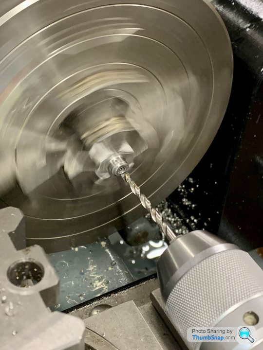
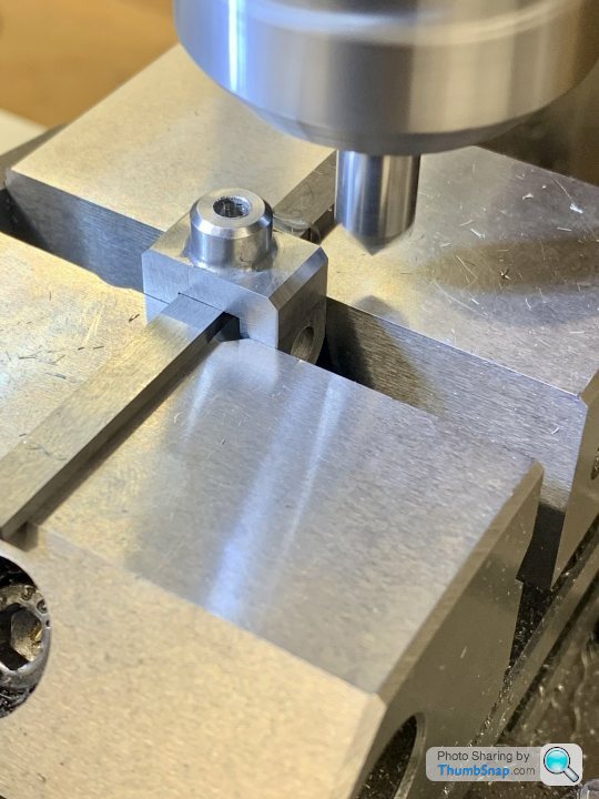
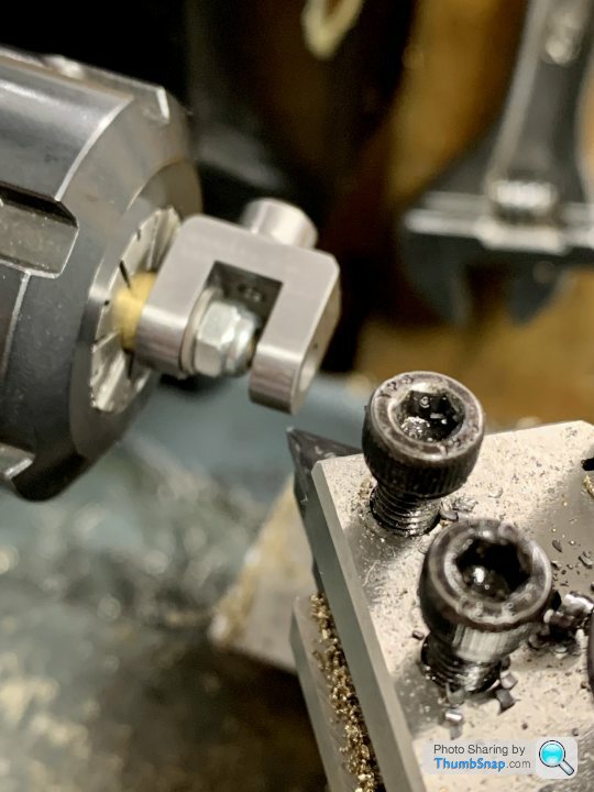
                              Drilled the counterbores on the fork bosses:

                              Also chamfered the bosses.

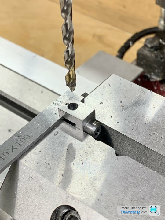
                              Then drilled the pin holes:

                              Turns out the pre-ream drill I used was too big, so the reamer didn’t cut anything. I measured the drill at 4.7 (same as I used for the brass sliders), but…anyway.

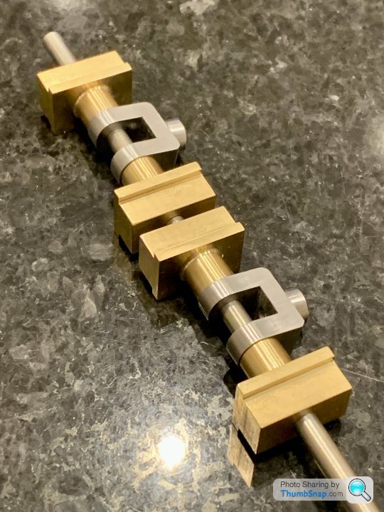
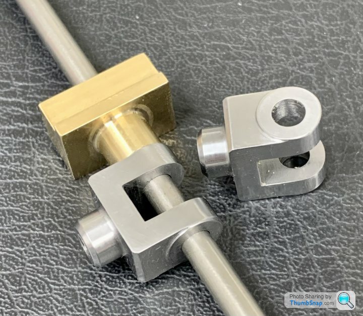
                              Made some filing buttons:

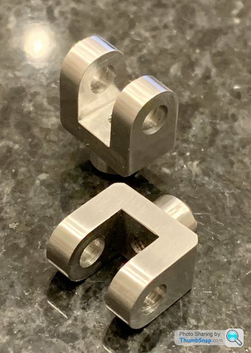
                              And filed the rounded ends:

                              Then chamfered the sides:

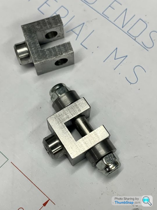
                              Progress so far:

                              I suppose I could hand ream the holes and brass blocks at 5mm, (which is about 0.009” more than 3/16&rdquo. I’ve already got a reamer and some 5mm stainless rod. Seems par for the course for me these days to end up correcting something, so no big deal.
                              #651358
                              JasonB
                              Moderator
                                @jasonb

                                You were lucky with the brass, 4.7mm is a bit large for reaming 3/16" on that sort of size I tend to go 0.2mm smaller so 4.5mm or 4.6mm

                                #651359
                                JasonB
                                Moderator
                                  @jasonb

                                  You were lucky with the brass, 4.7mm is a bit large for reaming 3/16" on that sort of size I tend to go 0.2mm smaller so 4.5mm or 4.6mm

                                  #651380
                                  Dr_GMJN
                                  Participant
                                    @dr_gmjn
                                    Posted by JasonB on 09/07/2023 06:53:58:

                                    You were lucky with the brass, 4.7mm is a bit large for reaming 3/16" on that sort of size I tend to go 0.2mm smaller so 4.5mm or 4.6mm

                                    Double- checking, I put 4.6 on the brass block drawing, 4.7 on the forks. I must have looked it up twice and rounded up on one, down on the other, or something daft. Anyway, I assume if I run through them all with a 5mm reamer I can do it by hand? Presumably it will self-centre, or should I setup in the mill?

                                    Re. The face bosses – seems like there’s about 0.3mm excess on the faces compared with the cross-piece, so to make them equal I could machine them leaving the bosses raised. Question is, having filed the rounded ends, I guess I might end up with a step on the radiussed end. Less chance of the if I mill them on the R/T, but easier to setup in the 4-jaw and turn them. Also I’ve not got a milling cutter with a 0.3 tip radius, but I’ve got plenty of turning inserts with 0.2mm radii, which would make a nice fillet.

                                    Any thoughts?

                                    #651399
                                    Bruce Voelkerding
                                    Participant
                                      @brucevoelkerding91659

                                      Dr_GMJn

                                      Taper Pins are made to 1/4" per foot taper on the DIAMETER – not the Radius as you queried on 7/7/23. 1/4" per 12" is 1:48 on Diameter, 1:96 on Radius. Note METRIC Taper Pins are 1:50 taper.

                                      When I use Filing Buttons in the Case shown above, I would make the Pivot Pin about .016" longer than the Sum of the thicknesses of the Part plus the 2 Rollers. I would put .008 x 45 deg Chamfers on both Ends – no Threads.

                                      Instead of the Nuts, clamp the assembled Parts in the Bench Vice (I have replaced all the serrated Jaw Inserts in my Bench Vices with smooth Brass Replacements). Note at this Stage the Part and the Rollers are free to rotate independently. I install a Screw in the Part to control its Position and I file until both Rollers rotate freely. It is satisfying to feel both the Rollers rotating – you know you are at Size and have not damaged the Roller Diameters.

                                      The Rollers are used unhardened and will last "forever".

                                      #651412
                                      JasonB
                                      Moderator
                                        @jasonb

                                        If you use a 5mm hand reamer that has a long tapered lead so should be OK to do it by hand and probably easier than trying to set up again under the mill spindle. Or you could put the parts into a vice that is free to move on the mill table which should allow it to self ctr.

                                        Doing the forks on the lathe would be easiest, stop just short of the rounded end and it won't show if you take too much. I'd probably just turn the end of a bar to 5mm, cut a short thread and fix part with a nut.

                                        #651447
                                        Dr_GMJN
                                        Participant
                                          @dr_gmjn

                                          Thanks Jason, that worked ok, although they might need a bit more hand rounding to get them spot-on. The bosses aren’t too pronounced, but they have equalised the thicknesses of the three bits of fork. I won’t bother increasing the side chamfers, because I think they look ok as they are:

                                          Still got to ream them, and I need to get some taper pins and taper reamer ordered. I think now they look much more refined and match the rest of the engine a bit better.

                                          Edited By Dr_GMJN on 09/07/2023 19:02:34

                                          #651449
                                          Dr_GMJN
                                          Participant
                                            @dr_gmjn
                                            Posted by Bruce Voelkerding on 09/07/2023 14:01:34:

                                            Dr_GMJn

                                            Taper Pins are made to 1/4" per foot taper on the DIAMETER – not the Radius as you queried on 7/7/23. 1/4" per 12" is 1:48 on Diameter, 1:96 on Radius. Note METRIC Taper Pins are 1:50 taper.

                                            When I use Filing Buttons in the Case shown above, I would make the Pivot Pin about .016" longer than the Sum of the thicknesses of the Part plus the 2 Rollers. I would put .008 x 45 deg Chamfers on both Ends – no Threads.

                                            Instead of the Nuts, clamp the assembled Parts in the Bench Vice (I have replaced all the serrated Jaw Inserts in my Bench Vices with smooth Brass Replacements). Note at this Stage the Part and the Rollers are free to rotate independently. I install a Screw in the Part to control its Position and I file until both Rollers rotate freely. It is satisfying to feel both the Rollers rotating – you know you are at Size and have not damaged the Roller Diameters.

                                            The Rollers are used unhardened and will last "forever".

                                            OK thanks, I’ll re-calculate and amend my drawing. I’d assumed the 1:48 taper was along one side only (in plan/elevation view).

                                            I did leave my in-hardened buttons loose, but the jammed occasionally during flatting, hence the damage. I think the forks look ok overall though.

                                            #651615
                                            Dr_GMJN
                                            Participant
                                              @dr_gmjn

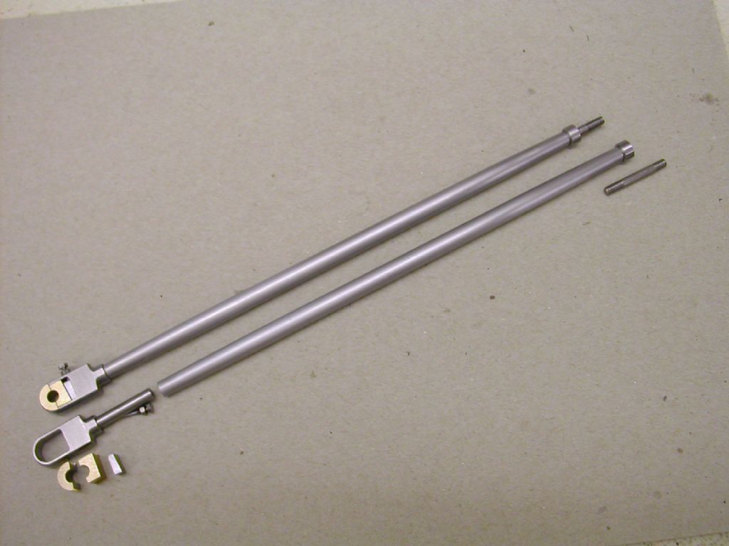
                                              I might have a go at the connecting rods next. I guess I have no choice but to make a tool for turning the end radii.

                                              I seem to remember some talk about fish bellied rods being more accurate than the plan versions, but can’t find it in the thread. There was some mention about the machining method bring wrong (which I did find), but no mention of the profile.

                                              Maybe the plan is ok after all?

                                              #651627
                                              JasonB
                                              Moderator
                                                @jasonb

                                                Which radii are you talking about

                                                I'll dig a post of mine out later for the bellies

                                                #651630
                                                Ramon Wilson
                                                Participant
                                                  @ramonwilson3

                                                  Hi Doc, I'm sure Jason will provide you with a good method to follow but for what it's worth I described making fish bellied rods on HMEM when making them for the Waller engine.


                                                  dscn3652.jpg

                                                  As you can see they are composite which makes for much easier machining – you can find the details here post #16 onwards (The description of making them is further on at the start of the second page of the thread)

                                                  Here's an image of the pair I made for my twin Vic using the same method. These ran at many shows over many years without showing any signs of their composite make up. The big end 'blade' was an integral part of the shaft.

                                                  dscf0430.jpg


                                                  Good to see you making progress – none at this end I'm afraid


                                                  Best – R

                                                  Edited By Ramon Wilson on 11/07/2023 07:45:23

                                                  Edited By Ramon Wilson on 11/07/2023 07:57:28

                                                  #651649
                                                  Dr_GMJN
                                                  Participant
                                                    @dr_gmjn
                                                    Posted by JasonB on 11/07/2023 06:48:55:

                                                    Which radii are you talking about

                                                    I'll dig a post of mine out later for the bellies

                                                    The end radii of the circular section rods, where then run out into the rectangular ends.

                                                    #651650
                                                    Dr_GMJN
                                                    Participant
                                                      @dr_gmjn
                                                      Posted by Ramon Wilson on 11/07/2023 07:42:03:

                                                      Hi Doc, I'm sure Jason will provide you with a good method to follow but for what it's worth I described making fish bellied rods on HMEM when making them for the Waller engine.

                                                      dscn3652.jpg

                                                      As you can see they are composite which makes for much easier machining – you can find the details here post #16 onwards (The description of making them is further on at the start of the second page of the thread)

                                                      Here's an image of the pair I made for my twin Vic using the same method. These ran at many shows over many years without showing any signs of their composite make up. The big end 'blade' was an integral part of the shaft.

                                                      dscf0430.jpg

                                                      Good to see you making progress – none at this end I'm afraid

                                                      Best – R

                                                      Edited By Ramon Wilson on 11/07/2023 07:45:23

                                                      Edited By Ramon Wilson on 11/07/2023 07:57:28

                                                      Thanks Ramon. Glad to see you posting here again.

                                                    Viewing 25 posts - 1,076 through 1,100 (of 1,206 total)
                                                    • Please log in to reply to this topic. Registering is free and easy using the links on the menu at the top of this page.

                                                    Advert

                                                    Latest Replies

                                                    Viewing 25 topics - 1 through 25 (of 25 total)
                                                    Viewing 25 topics - 1 through 25 (of 25 total)

                                                    View full reply list.

                                                    Advert

                                                    Newsletter Sign-up