Stuart Twin Victoria (Princess Royal) Mill Engine

Advert

Stuart Twin Victoria (Princess Royal) Mill Engine

Home Forums Work In Progress and completed items Stuart Twin Victoria (Princess Royal) Mill Engine

Viewing 25 posts - 951 through 975 (of 1,206 total)
  • Author
    Posts
  • #617744
    Ramon Wilson
    Participant
      @ramonwilson3

      That's a cracking image Jason, don't suppose you have one of the valve side too.

      I wasn't referring to the engine but the room floor area which though long appears quite narrow – some of the rooms that housed twin engines appear quite massive in area by comparison. Whilst there may be the odd one or so I can't recall any examples of wood floors in the larger rooms in any of the Watkin books I have but it's been quite a while since I was gleaning images for detail from those.

      As you are aware, I thought for a while that Doc was wanting to replicate a full size engine. As the intention is to build a nice model based on full size then it comes down to 'beauty is in the eye of the beholder' and I'm sure we will see just that at journeys end.

      Regards – R

      Advert
      #617745
      JasonB
      Moderator
        @jasonb

        Not one but two of the other sidesmiley click on them a couple of times and then the zoom tab comes up and you can see a lot of detail

        Edited By JasonB on 18/10/2022 18:09:15

        #617763
        Ramon Wilson
        Participant
          @ramonwilson3

          Thanks Jason, downloaded and savedwink

          yes

          #617807
          Dr_GMJN
          Participant
            @dr_gmjn

            Ramon – the idea was/is to build the Proncess Royal version of the Twin Victoria, pretty much to the plans from the magazine. For a second model and with my limited experience I think it's about the right amount of scale detail; it was never going to be some kind of perfect replica.

            I'm all for trying to make a few minor embellishments like glass oilers etc, but I'm also fine with it being 'semi-scale', such as with the main bearings we discussed previously. I suppose that attitude might seem strange, but I think I'll be happy with it once it's complete.

            The parquet thing was just a whim, and since I've not seen it before on an engine model I thought I'd have a go. If it looks a bit naff I'll bin it and try something else – probably plain wood.

            BTW the very first thing I noticed at the Midlands show last Saturday was the Twin Victoria on the Stuart Moldels stand opposite the main entrance. I was surprised to see it fitted to two separate free-standing base blocks (at least I couldn't see that they were connected by anything other than the crankshaft).

            #617831
            Ramon Wilson
            Participant
              @ramonwilson3

              Morning Doc, yes I do now realise that's how you see it, just that initially I thought your intention was to improve on the PR improvement so to speak.

              Even the basic Twin Vic is a nice model in it's own right so any embellishment however minor will improve matters. 'At the end of the day' the important matter is to enjoy what you do and how you do it.

              My input has always been based not on what you should do but what I have done and found to be the easiest to achieve an accurate result with minimal effort. I'd like to think that I have never made a comment on anything without previous experience of it and at times an example to show for it. Advice comes from different directions on any forum or indeed club room – but it's the individual that makes the choice and hopefully enjoys the process as a result.

              On that note your thoughts on a Parquet flooring may be a whim to some but it would certainly be an eye catcher from a display point of view. My thoughts are based on planking ships decks with similar width but much longer lengths of wood using cyano as said. I'm not sure I would want to tackle a parquet floor with CA as it can be difficult to control but I see no reason why (apart from its a big commitment) you should not give it a go. If you draw it out in Cad as you say with edging and all and place the model on top you'll soon get the idea of whether it's worth doing or not. Jasons idea of inserted areas of it is a good suggestion too.

              If you decide to go for plain wood may I suggest using lime – readily available in strips from various sources – an easy wood to work that takes a stain well and has a fine grain too – the latter being something to really consider from a scale effect point of view.

              I can't recall seeing the ST Twin Vic display model but to my mind a firm sub base on which to construct the model base is an absolute necessity – the firmer the better too as it's easy to wring something if not. Whether you then decide to put it on separate plinths is down to choice.

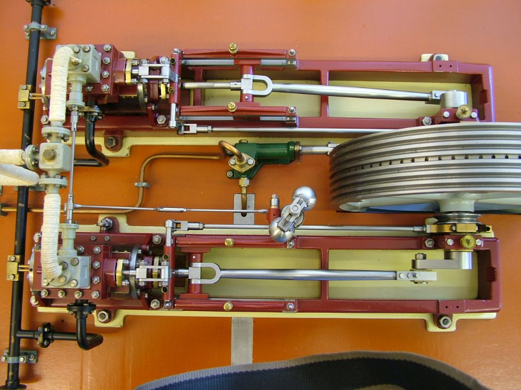
              Heres a top view of mine – main base is about 1" thick multi layer ply, a scrap piece I coined from somewhere – the plinths are MDF. Apart from the Corliss base which was a constructed affair all other engines have been on kitchen work top chip board with a hard wood border – very rigid.

              dscf0430.jpg

              All the best – R

              Edited By Ramon Wilson on 19/10/2022 08:45:49

              #618314
              Dr_GMJN
              Participant
                @dr_gmjn

                So today (actually yesterday at this time), I centre drilled the other end of the soldered brass bearing block, and did a few bits of lathe housekeeping ready for making the bearings.

                I can’t find Jason’s procedure, but I think I needed to use a thin parting tool to make the central groove where it fits into the housing. Question is how do I grind the steel tool exactly perpendicular? If the edge is slightly skewed, it’ll make a groove with a ridge at one end or the other. I’m concerned it won’t seat properly. Also, can you move a parting blade side-to-side to make continuous cuts?

                I also have an insert parting tool which I believe is deliberately skewed to aid break-through into a bore, or to form a point which breaks off when parting solid.

                Thanks.

                #618323
                JasonB
                Moderator
                  @jasonb

                  Bottom of page

                  If using your belt sander make a simple guide to keep it square, bit of MDF would do Other points covered in my post.

                  #618332
                  Dr_GMJN
                  Participant
                    @dr_gmjn
                    Posted by JasonB on 23/10/2022 07:05:20:

                    Bottom of page

                    If using your belt sander make a simple guide to keep it square, bit of MDF would do Other points covered in my post.

                    Thanks Jason, so “feeding in and then traversing side to side”, to me that means I’m using the parting tool like a normal cutting tool, but wouldn’t that just bend the tool because there are no cutting edges at the side? Or do you mean feeding in to a set depth, moving out, stepping over then feeding in again?

                    #618353
                    JasonB
                    Moderator
                      @jasonb

                      Once most of the material has been removed by plunging the last few thou can be done by moving sideways but only advance the tool a thou or so at a time, the tool will cut it.

                      If you are worried about leaving metal at the ends due to the grind of your tool a shallow 2-3 thou undercut can be used at either end.

                      #618408
                      Dr_GMJN
                      Participant
                        @dr_gmjn

                        Made a start.

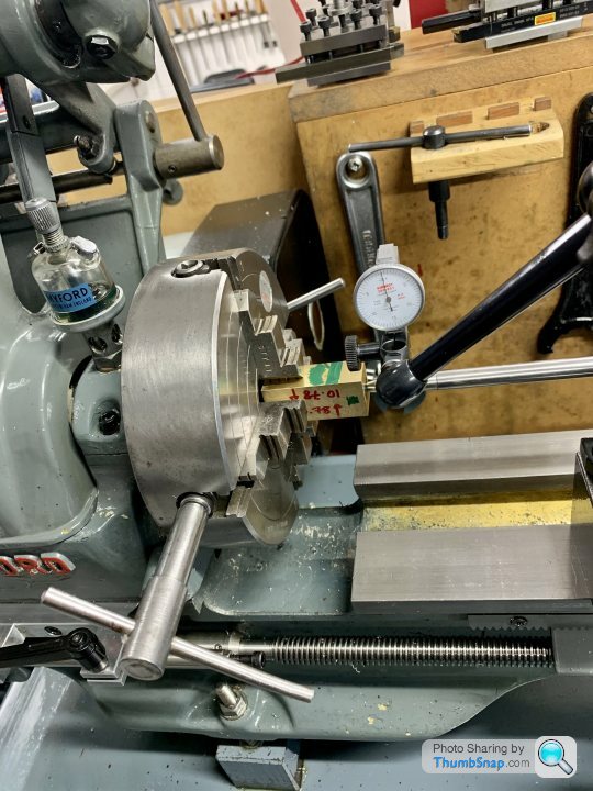
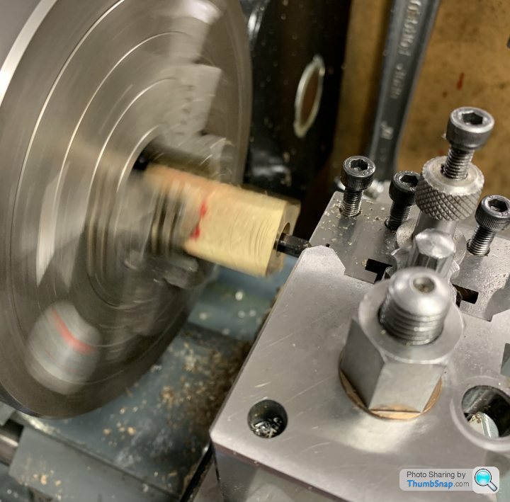
                        Centred the brass block:

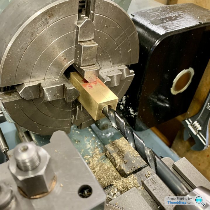
                        Drilled to 10mm so I could a) get a boring bar in, and b) give clearance for the crank spigot so I could test fit the crank shaft all the way along it’s journal:

                        Faced off to form a thrust face:

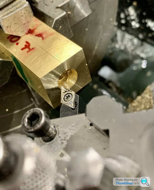
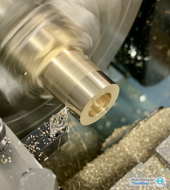
                        Then bored to a tight running fit on the crank:

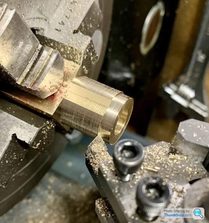
                        Then took intermittent cuts on the square to form the o/ds of the bearing side faces:

                        Unfortunately this partially broke the solder joint; when I test fitted the crank again, oil slowly bubbled out of the joint.

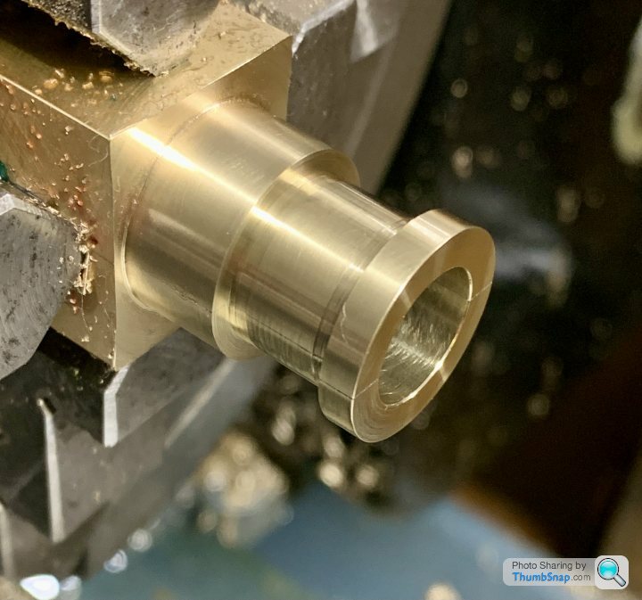
                        Anyway, thought I might as well carry on, so formed the bearing holder groove with a parting blade – deeper cuts at each end:

                        Test fitted until the halves just about closed:

                        It fell apart after final parting, but after cleaning the faces it looked fine:

                        There is a bit of a gap left when the cap is screwed down to a good running fit. If fully tightened it gets a bit too tight for comfort (but still turns). I expect once it’s been lapped in it’ll be spot-on:

                        The parted-off face needs thinning a bit, but I can do that with wet & dry on the surface plate.

                        I did make a mistake and over-bored a bit of the block at first, but hopefully I’ve got enough left to clamp in the chuck and make the other. Anyway, so far so good. Thanks for the advice.

                        #618685
                        Dr_GMJN
                        Participant
                          @dr_gmjn

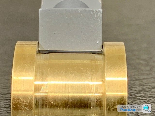
                          Hmm I thought there was something not quite right when I was test fitting and reducing the bearing diameters – it seemed like even though I was taking more off the inner flanks, it wasn't making a proportional difference to the fit. Eventually, despite finding it difficult to get consistent vernier readings (for obvious reasons now) they seemed to be a perfect fit, so I carried on.

                          It turns out that I've not ended up with straight sides, so the bearings are sitting on an edge at either side of the housing:

                          Both bearings are the same.

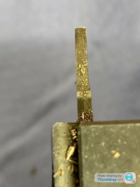
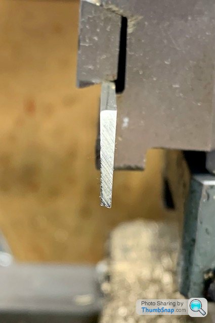
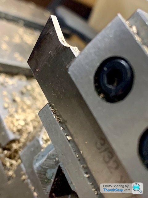
                          I set up the parting tool with a dti so that it was moving straight in and out of the workpiece, but looking closer at my parting tool, it seems to be tapered:

                          I knew it was a V-shape:

                          But I assumed its profile…

                          Would have made – if anything – a reducing taper the other way, such that the flanks wouldn't touch the work during feeding in. I still can't figure out what's going on there. Anyway it is what it is, and it's properly screwed the bearing fit.

                          Very, very annoying to find out after all that work. I can't really correct it either, because the machined grooves are now too small a diameter to be fit against the housing as it should be.

                          So I have a choice to make – leave it knowing it's wrong, or re-make the entire brass parts of the bearing. Functionally it probably won't make much difference…but it's wrong.

                          #618741
                          Dr_GMJN
                          Participant
                            @dr_gmjn

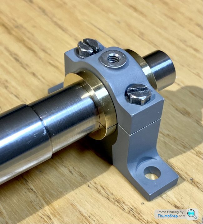
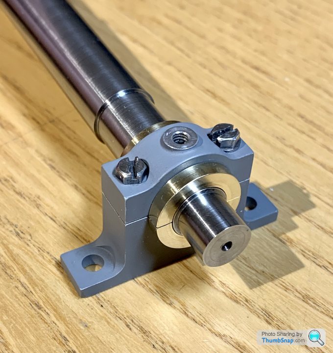
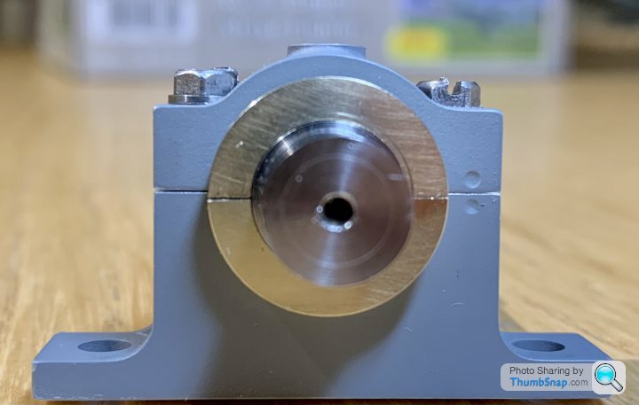
                            So this illustrates the issue:

                            Having noticed the bearing flange tapers, I pushed the inserts firmly into place with a plastic pen, it's clear to see there's now a gap, and the shaft wobbles.

                            The worst-case gap is 0.008" on diameter.

                            When the individual bearings are closed around the shaft by hand, the fit is spot-on. When further finger pressure is applied, the shaft binds slightly, so I think it's fine in terms of pre running-in fit.

                            At least this explains the rather suspicious perfect fit on initial assembly: the tapered sides were deforming the aluminium housings until the bearing halves are closed. But of course when they're pressed home (or the shaft gets loaded radially, the gap appears.

                            So I need to either shim the gap somehow, or start again with the bearings.

                            I could mill some of the housing mating faces, but 0.004" per side might be a bit much.

                            I suppose I could use release agent on the bearings and Milliput as a "liquid shim", but it's a bit of a bodge.

                            A metal strip shim would do for the gap, but then I'd be concerned that the oil from the cup would wick into the gap and bypass the bearing journal altogether.

                            Any ideas? Cheers.

                            #618742
                            roy entwistle
                            Participant
                              @royentwistle24699

                              Looking at the second photo of the parting tool, it doesn't look like the left hand corner is sharp. It could be a fault of the photo of course.

                              Edited By roy entwistle on 27/10/2022 11:57:56

                              #618751
                              Dr_GMJN
                              Participant
                                @dr_gmjn
                                Posted by roy entwistle on 27/10/2022 11:52:26:

                                Looking at the second photo of the parting tool, it doesn't look like the left hand corner is sharp. It could be a fault of the photo of course.

                                Edited By roy entwistle on 27/10/2022 11:57:56

                                Thanks Roy,

                                Sorry, I should have said – that's a picture of the back of the tool, not the cutting edge, I just posted it to show the section of the tool. I ground it on a wheel just before machining, so I know the other end was really sharp. It cut fine both plunging and side-to-side (with minimal depth of course).

                                I suppose it could have sprung, but there didn't appear to be anything amiss.

                                #618758
                                JasonB
                                Moderator
                                  @jasonb

                                  I can't really see how you could have got that tool tapered assuming it was just ground on the end, have you actually measured it as it could be the lense distorting the close up image

                                  If there is any flex in the setup then the tool can try and wander into the shallower side of the cut if you are just trying to widen it.

                                  There was a reason I said allow a bit on the width and heavily deburr the hole in the cap/pedestal.

                                  Best option to try and save things would be to put a good sizes flat chamfer around the hole so it can close up without touching the back of the bearing flanges and then work out how much too small the bearing waist is and wrap some shim around the bearing halves.

                                  #618787
                                  Dr_GMJN
                                  Participant
                                    @dr_gmjn

                                    Thanks Jason, It's a visible tapered side to the flanges when you look at them against some caliper jaws clamped around the i.d.

                                    I just tried it again on some scrap brass with the setup untouched from the last operation, and it forms tapered sides either incrementing sideways, or driving straight in.

                                    I can't *see* any issue with the flank of the tool, plus it comes to a point, so in theory there's no significant flank to generate a taper there anyway, but…eliminating all other possible casues leaves a ground tapered tool flank as the culprit. I can't remember why I ground the tool to that form, I'm not sure I even used it. Seems another case of me trying to grind HSS tools and failing miserably, only this time it's cost me dearly in terms of lost time and wasted effort.

                                    I'll have to try and find some insert tooling with flat-ended parting inserts (the one I have is slanted, and has a cut-out in the middle to generate some kind of swarf curl) so makes making a flat surface by traversing impossible over the full width.

                                    I've decided not to shim them; I've concluded that there was no point of being so careful with the housings, then making the bearings fit with chewing gum and string. I'll get some more brass and start over again (when I've got some motivation back, which I'd imagine will be quite a while).

                                    Cheers.

                                    #618790
                                    Dr_GMJN
                                    Participant
                                      @dr_gmjn

                                      I'll get one of these for next time, and bin the steel one:

                                      #618791
                                      JasonB
                                      Moderator
                                        @jasonb

                                        The end of those is not much different to what think you already have in the form of GT_N inserts both of which will move sideways even with the chip breaker edge and do have a radius to the corners that needs to be taken into account just like other turning inserts

                                        #618795
                                        Dr_GMJN
                                        Participant
                                          @dr_gmjn


                                          This is the one I've got – I can't see how it could be used for grooving as shown in the ARC image.

                                          The ARC inserts fr the one I posted are not the same as mine, they are flat-faced. The tip radius isn't a problem becasue theres a large chamfer on the inside of the housing:

                                          Either way, mine is shimmed up, upside down on the rear tool post, so for the sake of £25 I'd rather get another and use it just for this kind of thing.

                                          Edited By Dr_GMJN on 27/10/2022 18:45:47

                                          #618799
                                          JasonB
                                          Moderator
                                            @jasonb

                                            That's a handed insert designed to leave the pip on one particular side and suffixed either R or L. You need a neutral insert suffixed "N" hence my previous post GT-N.

                                            So you can use your existing holder but just replace with a neutral insert of suitable form

                                            Edited By JasonB on 27/10/2022 19:33:30

                                            #618874
                                            Dr_GMJN
                                            Participant
                                              @dr_gmjn

                                              Thanks Jason, As mentioned I think I'd rather leave the Sandvik tool permanantly set in the rear tool holder I made last year. It took some trial and error to get it placed properly.

                                              The Arc 8mm MGEH grooving tool looks like it would do, for the sake of £23.

                                              #618875
                                              JasonB
                                              Moderator
                                                @jasonb

                                                You can also get round nose inserts for those that are quite useful when you want a nice internal fillet

                                                #618876
                                                Dr_GMJN
                                                Participant
                                                  @dr_gmjn
                                                  Posted by JasonB on 28/10/2022 13:45:56:

                                                  You can also get round nose inserts for those that are quite useful when you want a nice internal fillet

                                                  Yes, I'll get a set of them as and when.

                                                  Off to get some more brass now…

                                                  #636613
                                                  Dr_GMJN
                                                  Participant
                                                    @dr_gmjn

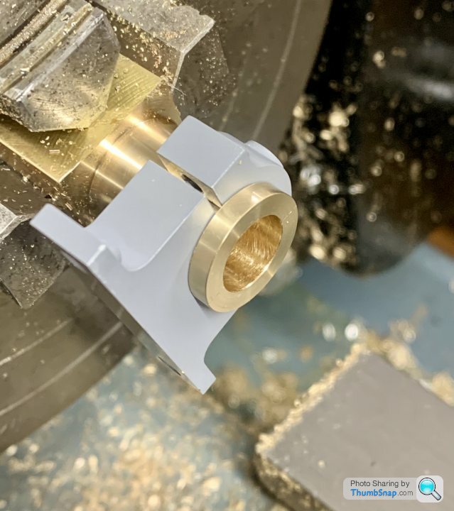
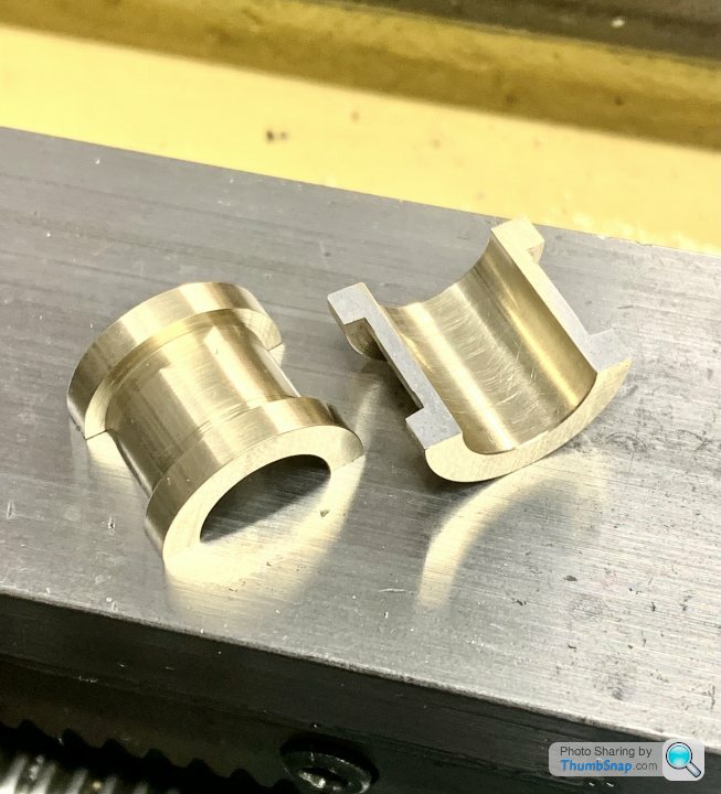
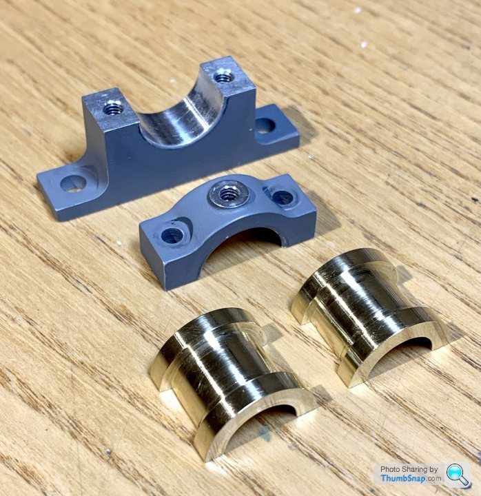
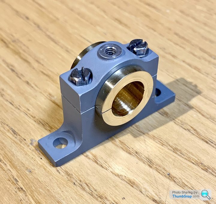
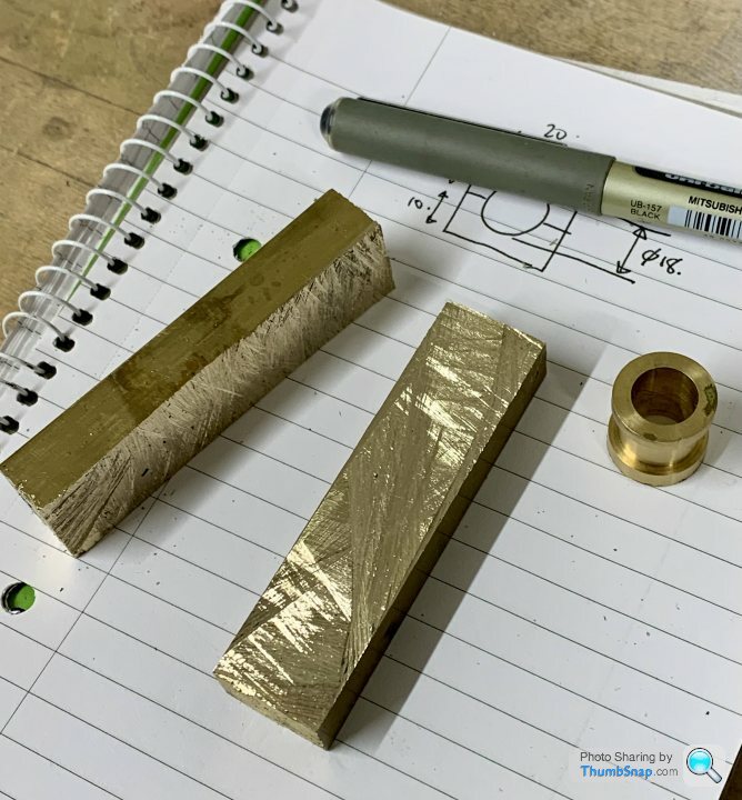
                                                    So after getting a bit demoralised over the bearing error after all that work (about 6 months ago – time flies) this evening I started again from scratch: cut the new brass bar to approximate size with the hacksaw:

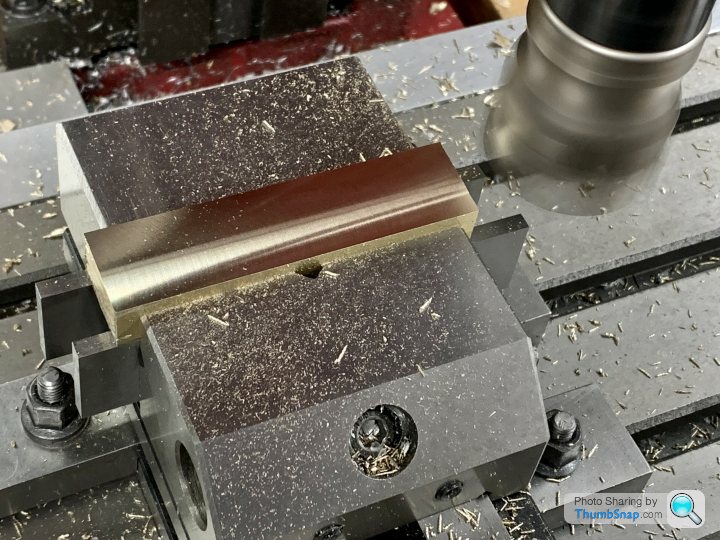
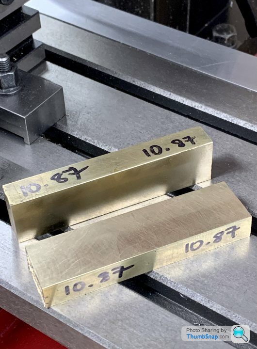
                                                    Then milled the mating faces and their opposites to the same thickness:

                                                    Now ready to solder together again, then final milling of the flanks and ends:

                                                    Hopefully I can get the solder to work a bit better this time too.

                                                    #636633
                                                    JasonB
                                                    Moderator
                                                      @jasonb

                                                      Good to see you back at it

                                                      One slight change to the sequence you could consider is turning the OD and recess for the pedestal first, Then you can actually clamp the pedestal around the bearing like a clamp which will help if the solder joint tries to open up.

                                                    Viewing 25 posts - 951 through 975 (of 1,206 total)
                                                    • Please log in to reply to this topic. Registering is free and easy using the links on the menu at the top of this page.

                                                    Advert

                                                    Latest Replies

                                                    Viewing 25 topics - 1 through 25 (of 25 total)
                                                    Viewing 25 topics - 1 through 25 (of 25 total)

                                                    View full reply list.

                                                    Advert

                                                    Newsletter Sign-up