Stuart Twin Victoria (Princess Royal) Mill Engine

Advert

Stuart Twin Victoria (Princess Royal) Mill Engine

Home Forums Work In Progress and completed items Stuart Twin Victoria (Princess Royal) Mill Engine

Viewing 25 posts - 51 through 75 (of 1,206 total)
  • Author
    Posts
  • #513800
    JasonB
    Moderator
      @jasonb

      Funny enough when sketching one out I did do a version with a rounded end to the base casting much like this engine but deleted the drawing a couple of weeks ago which would have given plenty of clearance.

      Advert
      #513811
      Dr_GMJN
      Participant
        @dr_gmjn

        Thanks both.

        Ramon – I just looked again at your model and noticed the cut-out. I didn't see it previously, and I don't think you mentioned it before. The P.R. I saw online didn't have the cut-out, but it did have a different bearing cap.

        Jason – I'd prefer the non-rounded end TBH. First it's easier to make, and second I'm not sure I like the aesthetics (obviously personal preference).

        I'll have a play about and see what it looks like extended. By my reckoning if the end is moved over by c.7 mm, it gives a c. 3 mm clearance on the bearing cap, which probably isn't the end of the world.

        #513964
        Ramon Wilson
        Participant
          @ramonwilson3

          Dr G – this project is one you can take 'as far as you like'. The big end can be changed, the end relieved or the sides extended. The choice is yours and will be fine however you do it. A google search should soon find examples of stationary engine connecting rod 'big ends' – there are quite a few to choose from and most would be in keeping.

          I don't quite understand though when you refer to the 'bearing cap' ?

          Ramon

          #513965
          JasonB
          Moderator
            @jasonb

            "Bearing cap" = keep plate on the end of the conrod's split bearing but that would be with marine type big end and PR uses a strap?

            If it is a marine type big end then there will also be fixings that stick out further to contend with too.

            Edited By JasonB on 17/12/2020 10:28:07

            #513968
            Ramon Wilson
            Participant
              @ramonwilson3

              Thanks Jason – always thought of that as bearing 'keep' – for some reason I was thing Doc G was meaning the main bearing hence the confusion – easy for me these days!

              I don't think too many mill engines were fitted with marine type big ends were they?

              #513971
              JasonB
              Moderator
                @jasonb

                No, a strap with a wedge or a rectangular hole in the end of the rod for the bearing and wedge to close it up would be more typical. The strap can always be made as a dummy if the Doc does not want to do the detailed PR version.

                #514187
                Dr_GMJN
                Participant
                  @dr_gmjn

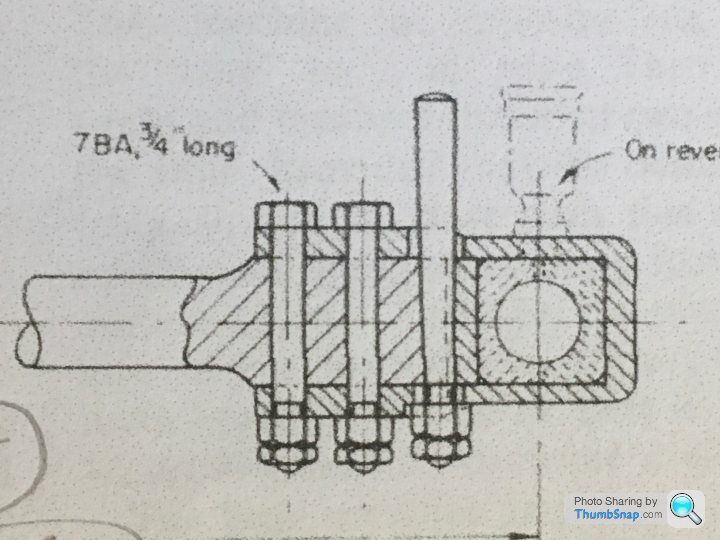
                  I was using car engine terms when I said bearing cap; I meant half the split block and retaining strap to the right of the drawing here:

                  Seems a very complicated way of doing things, but I guess it reflects reality.

                  I'd like to build it like that, as per the plans, although I might go mad and add the lubricator even though it's supposed to be for the reversing engine only. I know…crazy.

                  #514207
                  Ramon Wilson
                  Participant
                    @ramonwilson3

                    Hi Doc, I did mine to print but as you have already seen you need to make allowance for it on the end bar if so. I would imagine it is true to prototype but if not quite in keeping with the period.

                    You need to lubricate the crank pin even if non reversing. Either a simple type as shown but better (i.e. more realistic) if you do it through the end of the crankpin(s).

                    If you want to make see through oilers an ideal material for the 'glass' are those crystal clear tubes you get as protectors on artists brushes.

                    Ramon

                    #514231
                    Dr_GMJN
                    Participant
                      @dr_gmjn
                      Posted by Ramon Wilson on 18/12/2020 17:43:53:

                      Hi Doc, I did mine to print but as you have already seen you need to make allowance for it on the end bar if so. I would imagine it is true to prototype but if not quite in keeping with the period.

                      You need to lubricate the crank pin even if non reversing. Either a simple type as shown but better (i.e. more realistic) if you do it through the end of the crankpin(s).

                      If you want to make see through oilers an ideal material for the 'glass' are those crystal clear tubes you get as protectors on artists brushes.

                      Ramon

                      Thanks Ramon,

                      Yes – the one I'd seen that didn't have a cut-out had what I'd describe as a bearing cap, similar to a car engine. I think it's the marine type mentioned by Jason.

                      The plans show a rotating crankpin oiler, but they imply they're only for show…but that they do in fact sort of work. All a bit confusing actually. I'll go with the plans, and if they work, fine, if not I'll add an additional oiler through the strap.

                      #514237
                      Ramon Wilson
                      Participant
                        @ramonwilson3

                        Doc,

                        I've just fitted a rotating crankpin oiler to the engine I'm building at present. I sourced some 1mm OD copper tube for other parts but used this as the drip feed to the crankpin pick up. At first I thought that the viscosity of the light oil usually used for lubing running engines was going to be too thick to pass but it was not long before the oiler had emptied – if you are up for it they do work then and do look more in keeping than a oiler on the big end – well worth doing.

                        I did intend to fit this type of lubricator on my version – I think I even milled a pad to take a pedestal. I found the cups made recently but of course they never got fitted at the time.

                        Ramon

                        #514355
                        Dr_GMJN
                        Participant
                          @dr_gmjn

                          Ramon, do you have any drawings and/or photos of the oilers you mentioned you’d got working?

                          Thanks.

                          #514381
                          Dr_GMJN
                          Participant
                            @dr_gmjn

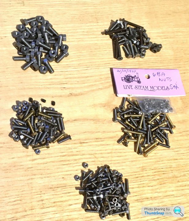
                            Nice little parcel arrived today from some kind person over on the PH forum – some BA fasteners that they had spare:

                            I suppose I should start sorting out my nuts and bolt storage boxes again – they have got into a bit of a state over the years…

                            #515642
                            Dr_GMJN
                            Participant
                              @dr_gmjn

                              I had chance to look at the cylnder castings more closely yesterday. They are much longer than the 10V, so I now appreciate why using a boring bar between centres is the way to go: Not only would the cylinders would be awkward to hold in any of the chucks I have, my largest boring bar would be pretty flexible at the extension from the tool holder I'd need.

                              #516210
                              Dr_GMJN
                              Participant
                                @dr_gmjn

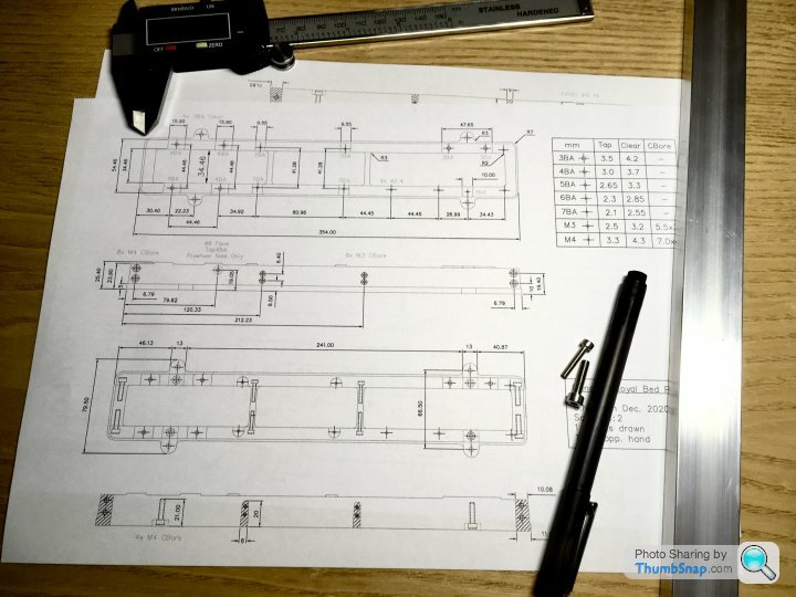
                                Got the fabricated bed drawings done – not quite to BS8888, and the check and approve process was a bit sketchy, but still:

                                #523936
                                Dr_GMJN
                                Participant
                                  @dr_gmjn

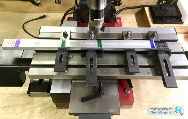
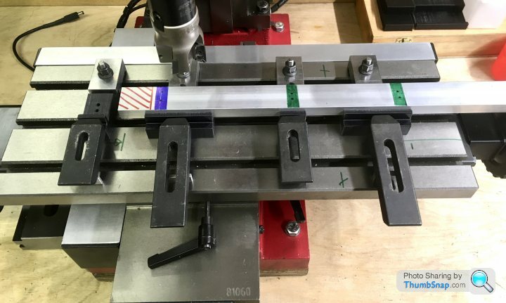
                                  Still too cold to do anything significant in the garage, so I thought I'd at least make some jigs to help get the tapers on the simulated bed castings right.

                                  First thing to do will be to mill the side bars to the correct overall length, then co-ordinate drill and counterbore all eight holes per bar. Each long side has two M4 screws to secure each end, and two pairs of M3 screws in the middle (slightly staggered), for the stiffeners.

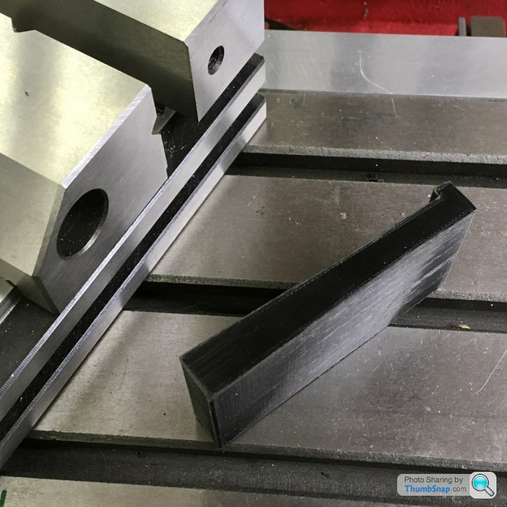
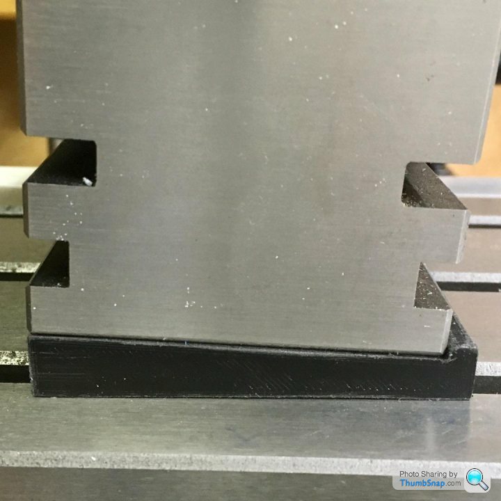
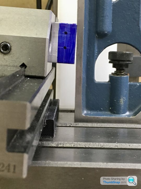
                                  Next job, while the bars still have parallel sides, will be to mill the draw angle on the ends. I 3D printed a wedge to fit under the vice to help get this right:

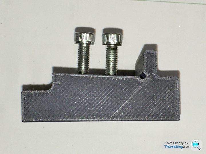
                                  The mill bed isn't long enough to machine the draw angle along the outer faces of the aluminium bar in one go, so I'll have to do it in two stages. I've made some more jigs to help with this. The jigs are flat on the bottom, and have the draw angle on their upper seating faces:

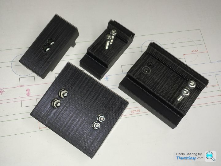
                                  I printed in some hexagonal pockets which securely grip nuts of the appropriate size. I can then just screw the bar to the jigs, and the heads will be below the cut face. There are four blocks, two with pairs of small holes, and two with large and small hole pairs, spaced such that they can be orientated on the bed accommodate both bar positions:

                                  I can hopefully move the bars to both positions without having to adjust anything, just by using different hole pairs:

                                  It's complicated by the middle hole pairs not being central between the end holes, so it's very easy to get confused and not end up with the correct handed parts with the counterbores and draw angle on the right faces. I will have to triple check and write down a machining sequence, but so far I think I'll need two configurations of jig to do everything correctly – basically turn the jigs as a set through 180 degrees on the bed. However, I wouldn't be surprised if another length of bar will need to get procured at some point:

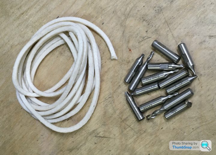
                                  Ramon kindly sent me some PTFE impregnated cord for the piston rings, and some scrap disposable tooling to grind to shape for the between centres boring bar I'll be making for the cylinders:

                                  #524064
                                  Ramon Wilson
                                  Participant
                                    @ramonwilson3

                                    Some nice thinking there Doc – I like the printed support blocks. Not familiar with 3D printing I assume the material must be of suitable resistance/hardness.

                                    Getting confused over mirror images is my forte – just had a session myself with a R/H pocket ending up in a L/H spot! Thank goodness for JB Weld though wink

                                    Good to see you've made a tentative start – it'll soon warm up in that garage

                                    Ramon

                                    #524082
                                    Dr_GMJN
                                    Participant
                                      @dr_gmjn
                                      Posted by Ramon Wilson on 01/02/2021 08:13:07:

                                      Some nice thinking there Doc – I like the printed support blocks. Not familiar with 3D printing I assume the material must be of suitable resistance/hardness.

                                      Getting confused over mirror images is my forte – just had a session myself with a R/H pocket ending up in a L/H spot! Thank goodness for JB Weld though wink

                                      Good to see you've made a tentative start – it'll soon warm up in that garage

                                      Ramon

                                      Thanks Ramon.

                                      The blocks are printed in PLA – it's a bit like nylon. I gave it a 50% solid honeycomb internal fill. It's way stiff enough in compression for this application. I printed them on their ends so that the profile has maximum accuracy. In this case though, accuracy isn't as important, as repeatability in that so long as when I put subsequent bars in the jig they all come out at the same angle.

                                      Yes, I've already confused myself with left and right hands for this. I think another two of the large blocks are needed, but of the opposite hand. I'll still probably get it wrong, which is why I'm using non-workshop time to try and figure it all out on CAD and write the sequence down!

                                      #530815
                                      Dr_GMJN
                                      Participant
                                        @dr_gmjn

                                        All, I've read a couple of times people suggesting putting black castings into an open fire and leaving them overnight, to soften them. I didn't have much issue with chilled castings on the 10V, although there were some areas that looked distinctly different shades after machining.

                                        Is it worth doing this? I'm just thinking it's getting to the time of year when we'll not be having many more fires, so thought I'd shove them in there next time.

                                        If it's worth doing, is there a risk of melting them? I doubt it, because after all the grate doesn't melt. We're using smokeless fuel on an open fire.

                                        Also, is there a set amount of time to leave them in there?

                                        Next question is on the between centres boring bar (again). What should the cutter geometry have, and can I do it on a rough grinding wheel, and finish it on the belt sander? Never done tool grinding before, and would rather avoid it altogether, but it seems like I need to learn it sooner or later. I hope I don't damage a casting; presumably if its ground wrong it'll be immediately obvious that something is amiss?

                                        Thanks!

                                        #530819
                                        JasonB
                                        Moderator
                                          @jasonb

                                          You have nothing to loose so chuck them in the fire to cook for the evening and leave in the ashes overnight. You can use an old file to see if any corners of thin sections are hard as it will just skate off the metal if they are.

                                          You can do it all on the grinding wheel but nothing wrong with finishing on a belt sander. I'll see if I can dig out a picture, think there are some in an album.

                                          EDIT, half way down the 4th line of images in this album there are 5 showing a suitable boring bar tool.

                                          Edited By JasonB on 28/02/2021 20:45:30

                                          #530830
                                          Dr_GMJN
                                          Participant
                                            @dr_gmjn
                                            Posted by JasonB on 28/02/2021 20:42:43:

                                            You have nothing to loose so chuck them in the fire to cook for the evening and leave in the ashes overnight. You can use an old file to see if any corners of thin sections are hard as it will just skate off the metal if they are.

                                            You can do it all on the grinding wheel but nothing wrong with finishing on a belt sander. I'll see if I can dig out a picture, think there are some in an album.

                                            EDIT, half way down the 4th line of images in this album there are 5 showing a suitable boring bar tool.

                                            Edited By JasonB on 28/02/2021 20:45:30

                                            Great, thanks.

                                            #531504
                                            Dr_GMJN
                                            Participant
                                              @dr_gmjn

                                              Cylinder lagging covers, or not?

                                              I do like the clean look of covers, then again the castings are OK as well on these. Can’t see any images of them with covers.

                                              Any comments? Personal preference or would it be one or the other on the real thing?

                                              Id want to plan the cylinder cap diameters and fettle the casting ends to form the right recess depth before making a start if covers are to be fitted.

                                              #531536
                                              Ramon Wilson
                                              Participant
                                                @ramonwilson3

                                                Hello Doc G

                                                If you are making something to represent a mill engine as PR does then you really need to lag the cylinders. Only a lot older and much smaller engines would have unlagged cylinders.

                                                I use tempered spring steel sheet which is easily worked and drilled. Colour can be done either in an oven if the temp will reach 280 plus or by laying in hot dry sand though the latter can be a bit too quick to change if you aren't ready for it. The sand needs to be hot before you introduce the lagging.

                                                Also – if using very small brass BA screws (14/16 BA) as fasteners – it's a lot less stressful to drill and tap small individual brass inserts in the lathe and fit them to suitable holes in the casting rather than drilling and tapping the casting itself.


                                                Edited By Ramon Wilson on 03/03/2021 22:50:58

                                                #531556
                                                JasonB
                                                Moderator
                                                  @jasonb

                                                  I've found thin aluminium works well as cladding and is easier to work with. Or if you want timber then thin strips glued to linen makes it a lot easier to handle as one sheet rather than loose strips and can be cut to a card template

                                                  #531561
                                                  Dr_GMJN
                                                  Participant
                                                    @dr_gmjn

                                                    Thanks both. I like the clean look of aluminium, and it’s easy to work as Jason says.

                                                    Would it be secured with a few screws around the cylinder end bosses in this case, or with screws underneath that are hidden? Might look a bit fussy with former.

                                                    Thanks.

                                                    #531563
                                                    JasonB
                                                    Moderator
                                                      @jasonb

                                                      You need to think what access they had on the original. easy enough for us to turn the model upside down to get at hidden screws but full size they would have needed to get to them. Probably a screw where the round end of the flange meets the vertical face of the steam passage. Just 4 of those if you want to do it as a single sheet but full size would most likely had one sheet each side so you need screws down towards the bottom of the flanges too.

                                                    Viewing 25 posts - 51 through 75 (of 1,206 total)
                                                    • Please log in to reply to this topic. Registering is free and easy using the links on the menu at the top of this page.

                                                    Advert

                                                    Latest Replies

                                                    Viewing 25 topics - 1 through 25 (of 25 total)
                                                    Viewing 25 topics - 1 through 25 (of 25 total)

                                                    View full reply list.

                                                    Advert

                                                    Newsletter Sign-up