Stuart Twin Victoria (Princess Royal) Mill Engine

Advert

Stuart Twin Victoria (Princess Royal) Mill Engine

Home Forums Work In Progress and completed items Stuart Twin Victoria (Princess Royal) Mill Engine

Viewing 25 posts - 401 through 425 (of 1,206 total)
  • Author
    Posts
  • #561235
    Dr_GMJN
    Participant
      @dr_gmjn

      Ok I’ll have a look at milling to profile when I get the table.

      The shape you drew would appear to need two setups – 1) to get the central large radii and tangent edges, 2) The the part would need offsetting on the table to centre the two outer radii?

      Advert
      #561237
      JasonB
      Moderator
        @jasonb

        That's it, one being done in this post

        #561261
        Dr_GMJN
        Participant
          @dr_gmjn
          Posted by JasonB on 04/09/2021 17:02:54:

          That's it, one being done in this post

          OK thanks. So what would be the best way of holding a part like the cylinder cover on the RT, allowing it to be easily re-centred for profiling?

          #561270
          JasonB
          Moderator
            @jasonb

            As I have it there with a vice on the R/T.

            Having located the ctr of the R/T under your spindle put a 1/4" dowel, bit of bar or reversed drill/mill bit into your collet. Valve chest in vice and then bring down the quill so the dowel goes into the gland hole and then clamp vice in place. You may find it easiest to put packing between fixed jaw and work so that the vice mountings line up with the R/T slots. This then locates the valve chest hole with the spindle and R/T axis so you can then off set the required distance to machine the 4 flats and larger arcs.

            Once they are done leave the vice clamped in place but put something in the collet that will fit the stud hole and just loosen vice jaw and slide the chest along until one of the holes is located and tighten the vice. You can now round one of the ends. repeat for the other.

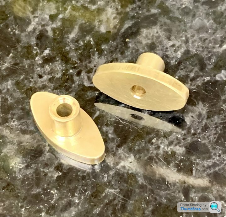
            Here is another one being done, in this case a piston rod gland which was larger so just clamped straight to the R/T. I also did the stud holes using the DRO to get their position either side of the central hole which was located centrally on the R/T & mill axis.

            Basic fabrication with rough shape of gland saw cut

            Located in 4-jaw, counterbored for gland and reamed for piston rod.

            The embryo gland was just a rectangular block with the spigot turned on it, placed in the main part once it had been clocked on the R/T and clamped together. Then offset either side to drill tapping size, drill clearance through gland only then tap for fixings.

            Replace gland clamp with a couple of screws and then mill one side followed by the other. The method is to rotate table to the required angle say 10deg and mill one flat until DRO is at the right reading that equates to cutter radius plus large arc radius then rotate table while cutting until you get to 10deg the other way, lock table and mill the next flat edge. Repeat for the other side

            Now remove one of the screws, loosen work on table and holed the clearance drill the wrong way round in the chuck so it can be used to locate one of the end holes while spindle is at 0,0 then clamp part, remove pin and replace screw. You can then mill one end round. repeat for the other

            take it apart and you have a boss that matches the gland

            There are other shapes of gland such as pure ellipse and one construction or the two long edges formed from arcs and the ends just rounded both need a different method.

            #561277
            Dr_GMJN
            Participant
              @dr_gmjn

              OK thanks, I will have to think this through – and hope my vice will fit the RT!

              I can see how it’s reasonably straightforward if you’re machining the oval shape from rectangular stock, but I am starting with an almost to-size part. So before starting the milling, I’ve got to make sure the three hole centres I’ve drilled are dead in line with the zero degree line of the oval. If not, the geometry will be lop-sided on the valve box face or cylinder cover, or even run off the cast material altogether?

              What I mean is, while the central hole is easy to find, the zero degree line (running through the three hole centres) also needs to be carefully set before starting? I guess I could do this by moving the x-axis on the mill and making sure by trail and error that the outer holes align with a drill in the collet? If all three holes are on that x-axis, that’s my zero line?

              When the first radii and tangent lines are done, and the part re-centred on the outer holes, it’s not too bad because I suppose I just rotate the RT until the end radii I’m cutting hit the straight lines at a tangent. It doesn’t really matter where I start or finish the cuts, because I’m judging the tangent intersection by eye at that point anyway?

              #561297
              JasonB
              Moderator
                @jasonb

                Yes usual way if part is going to be tight to get out of what is supplied or holes have already been drilled is to then locate my moving in say X and then rotating table until hole or mark under a pointer in the chuck. That's one thing I like about the ARC rotary table you can set the division ring around the table to zero rather than having to wok to each side of a random angle.

                #561315
                Dr_GMJN
                Participant
                  @dr_gmjn

                  Ok I think I’ll be able to figure out the fixturing detail when I get the RT now.

                  Do you just use the large angle scale? I guess it doesn’t have to be that accurate?

                  Also, is there a supplier of end mills with small tip radii? If I used one of those it would form a fillet and would save Milliput ring one I guess.

                  cheers.

                  #561327
                  JasonB
                  Moderator
                    @jasonb

                    A lot depends on the job, some things are OK with the scale, others I may just go two turns of a handwheel (90:1) others I will read the 10deg off the handwheel. Or if you look at the one in the MEM link I scribed a couple of circles at the ends and simply kept turning the R/T until the cut kissed the scribed circle.

                    You can quite easily make your own cutter from one that has become blunt, as it is usually the corners that go first simply freehand grind or even use a diamond lap to round off the corners, doe snot need to be the perfect 1/4" circle as the 3 or 4 flutes will even things out.

                    If you want to buy then I have a few of these, I should think 4mm dia x 1mm radius would be about right for the Victoria.

                    #561418
                    Dr_GMJN
                    Participant
                      @dr_gmjn

                      Thanks Jason, I’ll look at getting a radiussed cutter I think.

                      Made some progress on the steam chests today. I may have done this arse about face, but it seems to have worked…

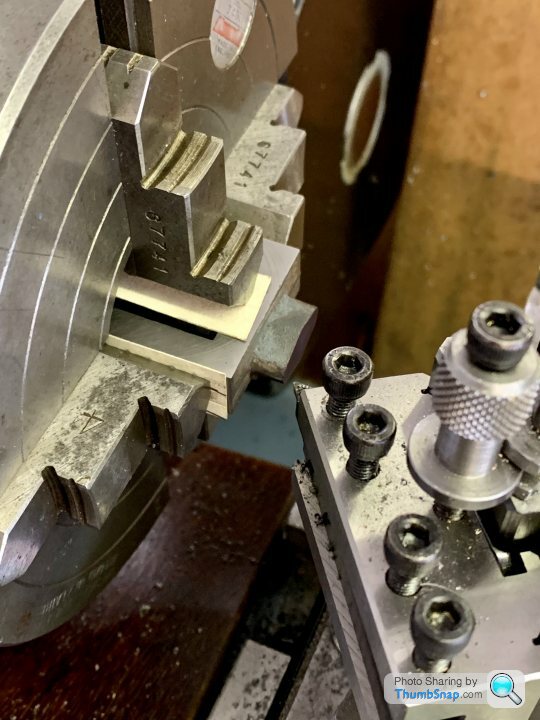
                      Started by putting the chests in the 4-jaw and cleaning up the gland faces (not to any particular dimension)

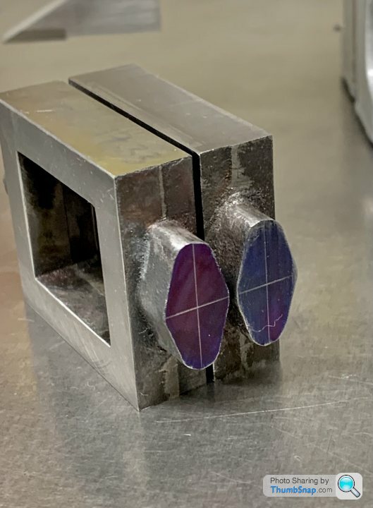
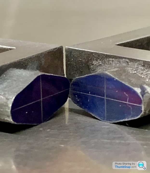
                      Then using the height gauge, scribing the centres of the ovals by measuring the major and minor dims, and offsetting the scriber by half:

                      From there I could easily figure out how much to remove from the previously cleaned-up faces:

                      Then the sides, making them all the same as the minimum clean-up side:

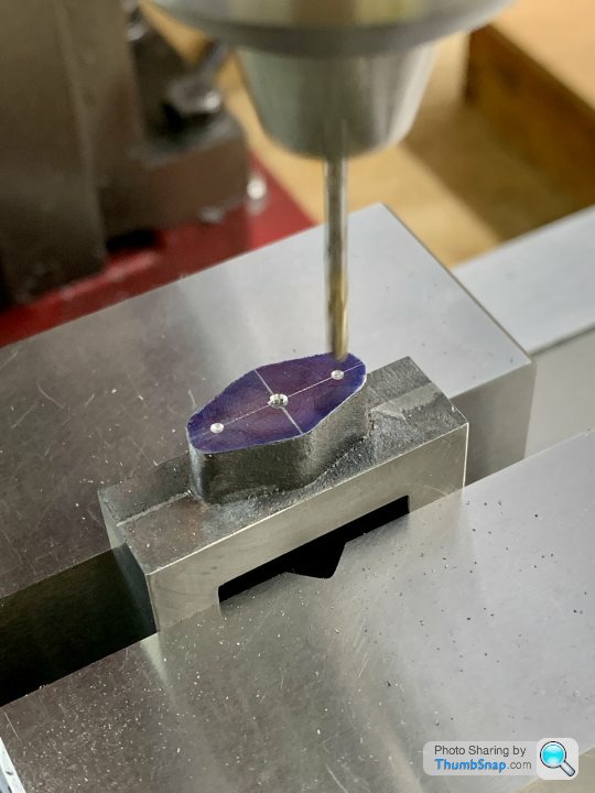
                      Then set up in the mill to drill some pilot holes for the flanges:

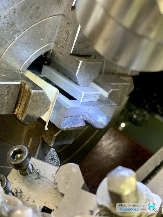
                      Then setup in the 4-jaw to get the valve rod hole centred (its offset). Once set, I loosened 2 of the jaws, and spun the part 180 degrees so I could machine the dome end:

                      This cleaned up OK:

                      And the other:

                      They actually measure within a few thou of each other in overall height, which is surprising since the end facing of the ovals wasn’t to a dimension yet:

                      Slightly concerning that even without the oval ends being machined, they’re very short to the valve face pads:

                      Still, I only did the absolute minimum clean-up so it is what it is:

                      Very pleased with the height gauge – it got lots of use already, and made things so much easier for these parts. Now waiting for the RT to arrive – just in time for profiling the oval bosses.

                      BTW, also increased the drain slots from 2mm to 3mm long.

                      #561424
                      JasonB
                      Moderator
                        @jasonb

                        They are not really that much too short if at all, it's the draft angle that is making them look short. The corners are about right it is just the valve face gets longer as it gets towards where the parting line was on the casting, if they made it straight the pattern would not pull out of the sand. The alternative would be having the ends of the valve chest shaped like this < > to match the valve face ends which would be worse

                        Once the chests are drilled and complete, blue the port face, screw on the chest and scribe a line along the ends of the chest. File off the excess or use your new radius corner milling cutter

                        #561426
                        Dr_GMJN
                        Participant
                          @dr_gmjn
                          Posted by JasonB on 05/09/2021 19:28:48:

                          They are not really that much too short if at all, it's the draft angle that is making them look short. The corners are about right it is just the valve face gets longer as it gets towards where the parting line was on the casting, if they made it straight the pattern would not pull out of the sand. The alternative would be having the ends of the valve chest shaped like this < > to match the valve face ends which would be worse

                          Once the chests are drilled and complete, blue the port face, screw on the chest and scribe a line along the ends of the chest. File off the excess or use your new radius corner milling cutter

                          Yep, that’s the plan. There’s still some cosmetic work on the cylinders anyway, like getting a couple of the flanges to match the minimum cap diameter, so I’ll do that at the same time. I can see the edges have got draw on them, so they should be OK. The chests are pretty short though according to the drawings. IIRC about 0.75mm to 1mm.

                          Im wondering if to side mill the inner faces of the chests, particularly the ends. Firstly so that the valve rod drill doesn’t skip on the rough surface, and secondly to make sure there’s clearance for the valve.

                          #561427
                          JasonB
                          Moderator
                            @jasonb

                            Quick file will do just to tidy them up and as you say give the drill half a chance of staying in the right place

                            #561995
                            Dr_GMJN
                            Participant
                              @dr_gmjn
                              Posted by JasonB on 05/09/2021 10:09:19:

                              A lot depends on the job, some things are OK with the scale, others I may just go two turns of a handwheel (90:1) others I will read the 10deg off the handwheel. Or if you look at the one in the MEM link I scribed a couple of circles at the ends and simply kept turning the R/T until the cut kissed the scribed circle.

                              You can quite easily make your own cutter from one that has become blunt, as it is usually the corners that go first simply freehand grind or even use a diamond lap to round off the corners, doe snot need to be the perfect 1/4" circle as the 3 or 4 flutes will even things out.

                              If you want to buy then I have a few of these, I should think 4mm dia x 1mm radius would be about right for the Victoria.

                              Would they be OK for milling the recesses in the valve chest covers? I suppose in theory they sould be slot drills for that. The depth is about 0.8mm IIRC.

                              #562034
                              JasonB
                              Moderator
                                @jasonb

                                Yes, ideal for that sort of job and would not need to be 2-flute slot drills anyway

                                #562623
                                Dr_GMJN
                                Participant
                                  @dr_gmjn

                                  Bit of advice needed on the gland bosses please:

                                  Firstly, my plan is to mount the chests in the 4-jaw chuck, and clean up the outer parts of the gland-end faces by turning. That will give me a datum depth to set the cutter to after transferring to the mill; I can set the milling cutter to, say, 0.01mm lower than the cleaned-up bits of the face, and hope the un-touched parts right next to the boss are higher and will clean up during the boss profiling. You might be able to see I messed up the face depths on the aluminium test part below. This was because I had to remove the cutter to re-centre the part using a drill bit, and misjudged re-setting it.

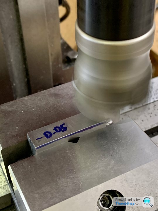
                                  Anyway, after getting used to the feel of the R/T on the r/c car parts, I tried profiling some scrap aluminium to dimensions I think will just fit on the bosses:

                                  I did the flats first, then the large radii, then re-positioned for each end radius. What I found pretty much impossible to judge was when to stop turning the R/T when the tangent was reached. By a lot of trial and error I managed to get it about right, and blend the slight remaining ridges with abrasives.

                                  Thinking about it, would this be better:

                                  1) Turn the R/T and machine a flat (cutter moving right to left), until x=0.

                                  2) While still cutting, rotate the R/T to the correct angle and continue in x until the cutter runs off the part.

                                  3) Move in y and do the same at the other side.

                                  Still leaves the end radii, but not much to be done about that:

                                  I'm setting up like this for the valve chests:

                                  So a bit easier to re-position for the small radii than a circular part because I'd just slide the part over in the vice until a drill fits into the end holes.

                                  On the aluminium test part, for setting up, I:

                                  1) Centred the R/T using the x/y table, and zeroed the DROs.

                                  2) Placed the vice on the table and aligned it using a drill into the pilot hole in the clamped part.

                                  3) Adjusted the table rotation until the fixed jaw read zero across it's face when traversing in x, using a dial gauge.

                                  Not sure if that's the easiest method, but it seemed to work?

                                  If I lock the R/T, the backlash on the handwheel is about 6', which measured as a distance at the end of the lobes on the gland boss barely registers on a dial gauge. I wonder if I can rely on the scale to get things tangential enough without judging it by eye? For example if I'm rotating the wheel/table back and forth at the end radii, will that amount of backlash even be noticeable if I rely on the handwheel scale to get things tangential, rather than by eye?

                                  Sorry for the long-winded post, but it's a whole new process, and with a new toy.

                                  Cheers.

                                  #562628
                                  Ramon Wilson
                                  Participant
                                    @ramonwilson3

                                    Haven't checked in for a while Doc – good to see more progress yes

                                    Might be a bit late in the day now but theres a much simpler method of making the gland bosses. As much as I enjoy using a rotary table this is one of those instances when it really isn't neccesary.

                                    Have a look here post 472 onwards for a much easier way. They won't neccessarily match the casting but then they rarely do in full size situations but they do all come out identical within the remit of hole spacing and filing buttons.


                                    Regards – Ramon

                                    Edited By Ramon Wilson on 13/09/2021 15:58:09

                                    #562629
                                    Ramon Wilson
                                    Participant
                                      @ramonwilson3

                                      Reading your last post through, I'd be inclined, as said, to set the spindle to zero on the boss hole. Move the R/T either a known angular amount or by eye – if the latter make a note of the setting on the dial. Take a cut either side of centre to do opposing faces to the same setting each side. Rotate table known amount or to the same setting as previous. Repeat cutting to same setting to do the other two faces.

                                      Carefully file main and end radii using a filing button if accuracy is required

                                      You could still use the R/T to do the main radius (or indeed the ends) but as you say run the risk of over shooting – an easy thing to do on an R/T


                                      Hope that's of use too


                                      Ramon

                                      Edited By Ramon Wilson on 13/09/2021 16:12:01

                                      #562684
                                      Dr_GMJN
                                      Participant
                                        @dr_gmjn

                                        Nice to see you again Ramon. Yes, since I just got an R/T, I really want to use it on these! I thought about filing buttons, but since the gland boss is stuck straight to the chest, I think I’d probably end up filing into the chest as well. However, as I mentioned, I’ll probably end up leaving slight ridges at the tangent points which I’ll blend with abrasive sticks or something.

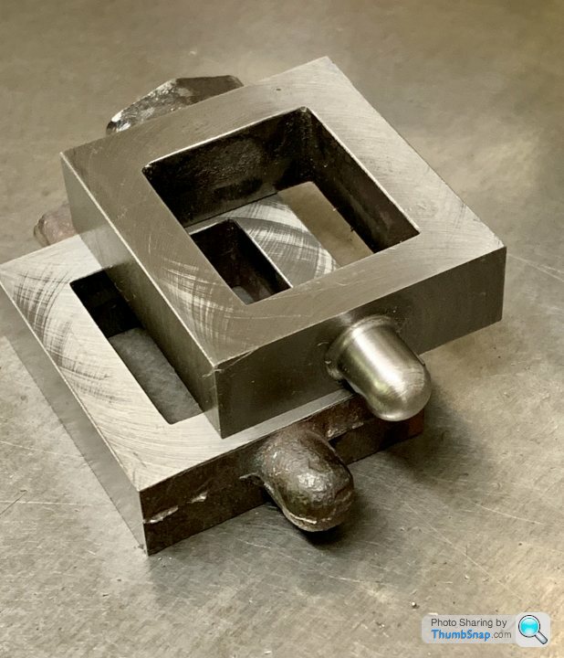
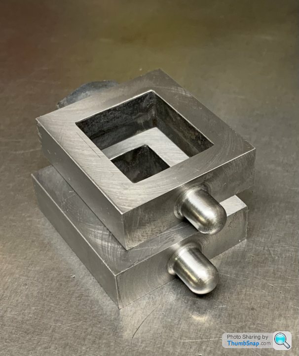
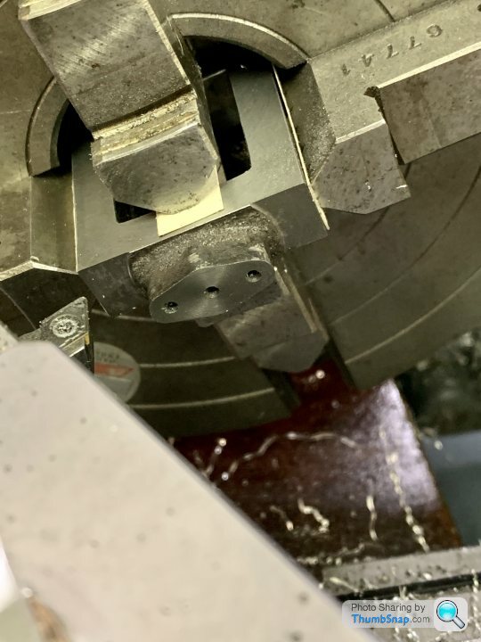
                                        I cracked on anyway: mounted the chests in the 4 jaw chuck and skimmed the faces to give a consistent depth datum to mill to. Both chest lengths are the same now at the machined faces:

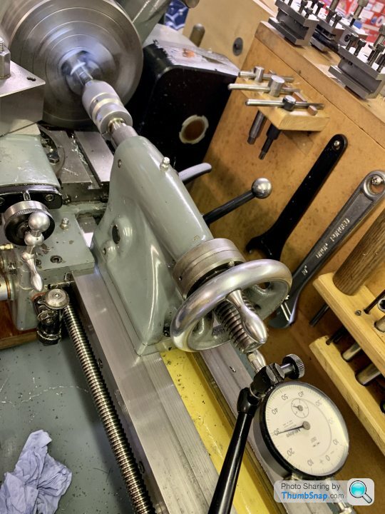
                                        Then drilled the valve rod holes (as per the article) and packing space. The latter should have been ‘bored’ but I don’t have a boring bar that small. Couldn’t see why it was that critical anyway, since I was making the gland bosses to suit:

                                        Also faced the boss again to get the right protrusion:

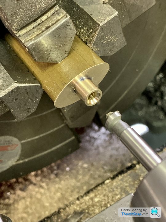
                                        Then set the gunmetal extrusion in the 4-jaw and turned the spigot to fit the packing hole:

                                        Didn’t fancy parting it off, so went at it with the hacksaw:

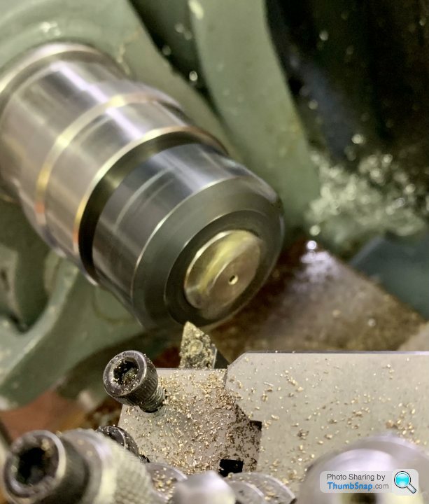
                                        Then reversed it and put in the collet chuck to face the front:

                                        Finished:

                                        Just need the 7BA clearance holes drilling, then I can bolt them to the chests for milling the sides:

                                        You can see how oversized the gunmetal is here:

                                        If I’ve done my sums right, the mill profile should just skim the cast iron boss and in the process take the excess gunmetal with it, leaving them identical. This will probably the trickiest bit of machining I’ve done so far. I hope it works out OK.

                                        Edited By Dr_GMJN on 13/09/2021 21:30:43

                                        #562717
                                        JasonB
                                        Moderator
                                          @jasonb

                                          I do them as you showed in your sketch feeding along one edge, rotate table for the larger dia arc and then feed along the other flat.

                                          A couple of vice stops will allow you to locate the two stud positions before you start milling sliding the chest to one side and setting the stop and then same for the other. You can then locate the rod hole and mill then simply slide the chest along to one of the stops and mill the end etc. So no tool height loss. Though you should be able to get close enough resetting that any difference will come out with the final file/emery work.

                                          #562721
                                          Dr_GMJN
                                          Participant
                                            @dr_gmjn

                                            OK Thanks Jason.

                                            I made some stops for the vice which bolt across the ends. They aren’t adjustable though. Is there a method for making adjustable stops, or is it a case of packing from the ends?

                                            #562964
                                            Dr_GMJN
                                            Participant
                                              @dr_gmjn

                                              I’ve made these side plates for the vice, with screws in them:

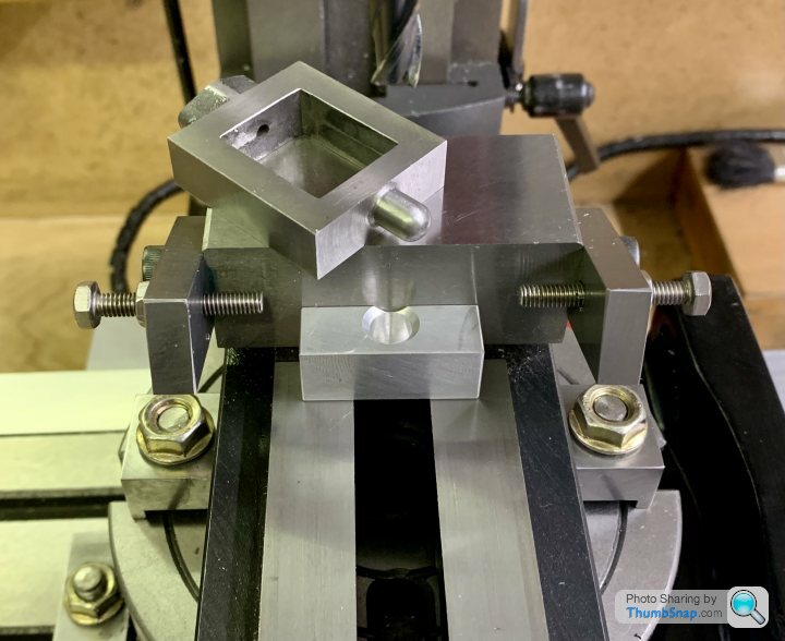
                                              Also had to make a block to sit the chests in so the dome clears the vice slot:

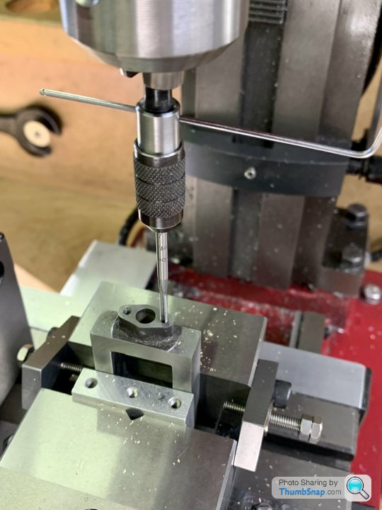
                                              So the process would be to set up central to mill the large radii and flats:

                                              Then to one side and the other, with the screws pre-set to put the end holes under the spindle for doing the end radii:

                                              I think that was the approach suggested, unless I’ve missed something?

                                              With the lower spacer, the height is approaching the useful limit of the mill, and it’s not a big part. Anyway, hopefully it will work out.

                                              #562975
                                              JasonB
                                              Moderator
                                                @jasonb

                                                That it, you don't need to change tooling once you start milling so can maintain the height setting.

                                                #562980
                                                Dr_GMJN
                                                Participant
                                                  @dr_gmjn

                                                  Thanks, Im not bothering a radiussed cutter for this: one part has a bit of a radius (may be sand residue) the other is a clean corner all round.

                                                  Im planning on using an 8mm or 10mm cutter, since I assume the extra stiffness will be beneficial over a 5 or 6mm one?

                                                  #563376
                                                  Dr_GMJN
                                                  Participant
                                                    @dr_gmjn

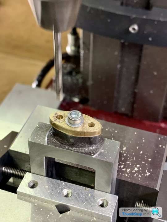
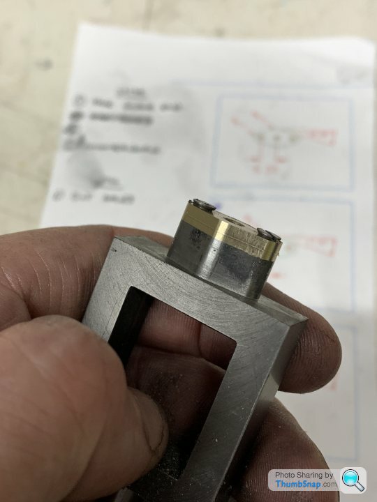
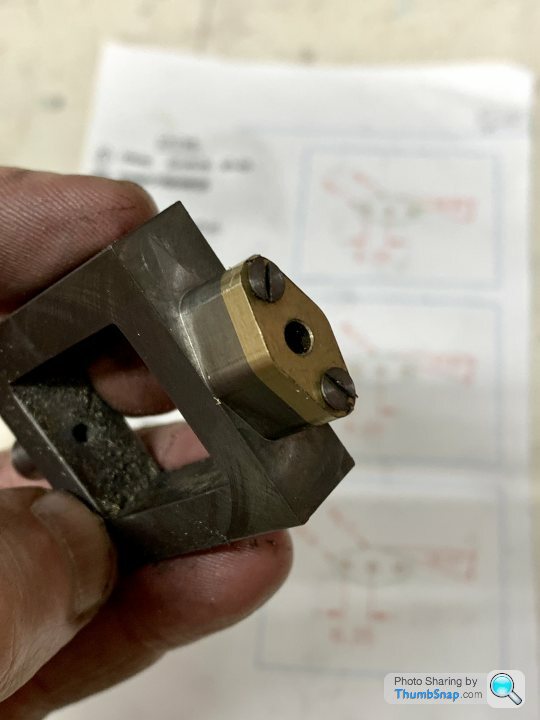
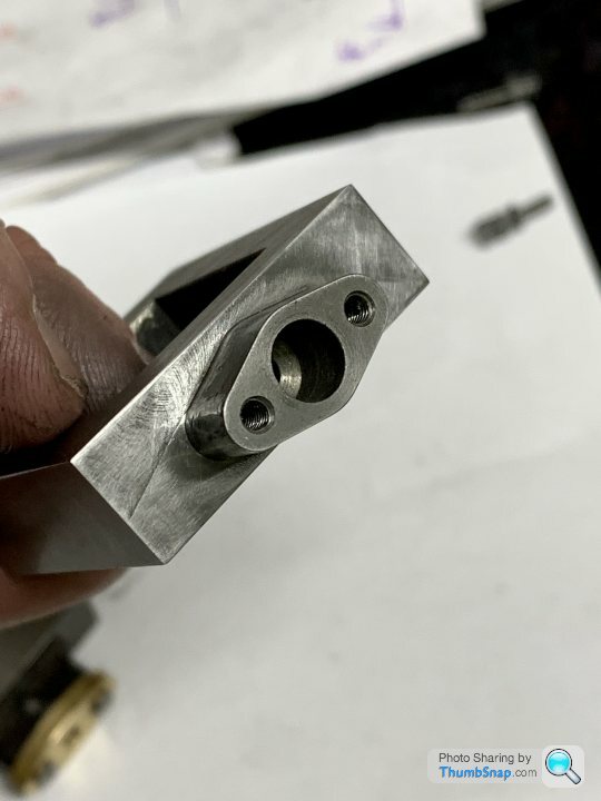
                                                    Temporarily clamped the bosses to the castings, and drilled the 7BA clearance holes using the DROs:

                                                    Then tapped the stud holes:

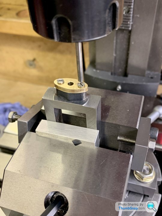
                                                    Then fixed them using 7BA csk screws ready for machining, and centered the vice on the R/T:

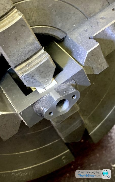
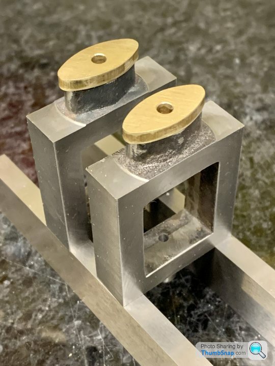
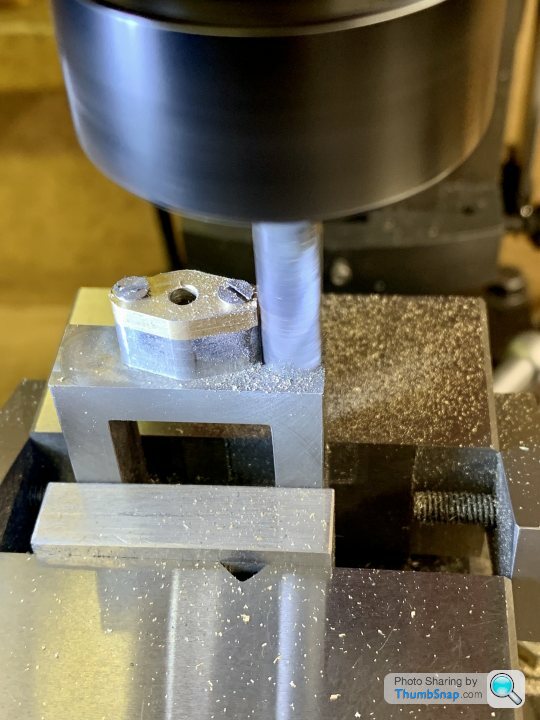
                                                    Then, after much adjustment, centering and angle calculation, made a start on milling the profile while periodically moving in x, then rotation in z, at gradually increasing depts of cut. I tried to always move the table clockwise for this to reduce backlash errors:

                                                    Then re-centered on each end, using the vice stops, and rotated the table to give the radii:

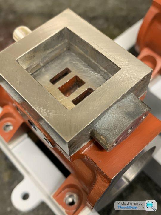
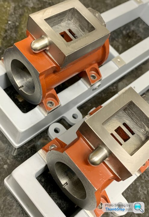
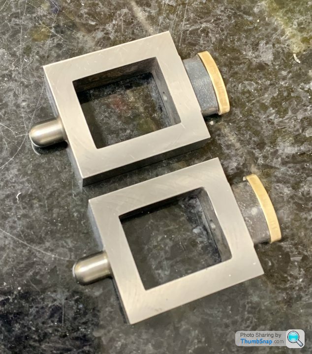
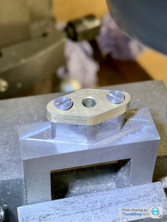
                                                    Turned out OK for a first attempt:

                                                    Before and after:

                                                    Needs some flatting of the machining marks, despite using a constant z-setting for all the final cuts. Not a big deal in this case because they will be painted eventually, and so could be filled if they won’t flat out:

                                                    Now for the other one…

                                                    By the way, what is the best way to flat out machining marks like this? I’m sure I’ll get some in the valve chest cover recesses, and those won’t be painted, so I really want them smooth.

                                                    Thanks.

                                                    Edited By Dr_GMJN on 18/09/2021 22:01:00

                                                    #563390
                                                    JasonB
                                                    Moderator
                                                      @jasonb

                                                      You could have taken a couple of cuts in Y while still set up for the main shape which would have got rid of most of those two "V" shapes you have either side before moving the part for the ends, maybe try that on the second.

                                                      Fine and then Emery paper backed by a file is the usual way in my workshop, also tend to paint any recesses covers just leaving the raised edge bright.

                                                      Shape looks good.

                                                      Edited By JasonB on 19/09/2021 06:57:14

                                                    Viewing 25 posts - 401 through 425 (of 1,206 total)
                                                    • Please log in to reply to this topic. Registering is free and easy using the links on the menu at the top of this page.

                                                    Advert

                                                    Latest Replies

                                                    Viewing 25 topics - 1 through 25 (of 25 total)
                                                    Viewing 25 topics - 1 through 25 (of 25 total)

                                                    View full reply list.

                                                    Advert

                                                    Newsletter Sign-up