Stuart Twin Victoria (Princess Royal) Mill Engine

Advert

Stuart Twin Victoria (Princess Royal) Mill Engine

Home Forums Work In Progress and completed items Stuart Twin Victoria (Princess Royal) Mill Engine

Viewing 25 posts - 351 through 375 (of 1,206 total)
  • Author
    Posts
  • #557381
    Ramon Wilson
    Participant
      @ramonwilson3

      Hate to think what they cost let alone the postage Jason – where is 'Little machine Shop' based BTW.

      This is not about being frugal however but being practical.

      At coming up for 77 I (attempted) to grind my first tool around 1972 so near on fifty years worth. It was not pretty no doubt – the bench grider was one of those Black and Decker geared ones that sounded like it was going to self destruct at any moment but the experience has served me well. Carbides were of course available but these were brazed tools not inserts – it would be years before I used such. Only means of 'grinding' (?) those brazed jobs at home was to 'wear' them down on a green grit wheel.

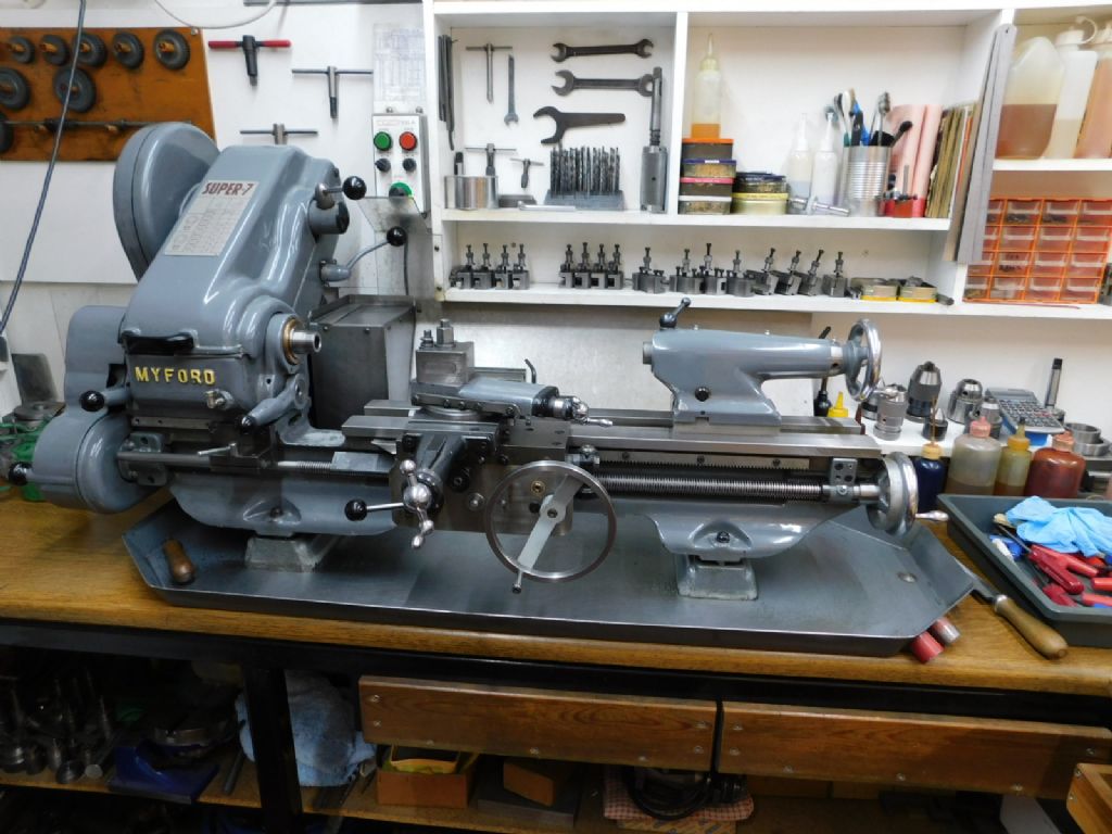
      My Super 7 has served me well since 1979 and is still in good order – I hate to think however what it would be like if I had flogged it trying to use carbide tooling instead of HSS over the years.

      Advert
      #557384
      Ron Laden
      Participant
        @ronladen17547
        Posted by JasonB on 07/08/2021 10:10:31:

        HSS inserts are available from Warner and Little machine Shop, a few over on MEM like them plus a few here.

        The need to "work" the carbide applies a lot more to the **MT as they do not have any where near as sharp an edge as the **GT inserts which will happily take 1thou cuts. Even on teh MT if you go for the "LF" or similar ones they will take quite light cuts as they are designed for "Light Finishing"

        Doc , if your GT inserts are not surviving taking that bit of 1.25" down to 1" then something is not right.

        Do I take it Jason there is no UK supplier of HSS inserts.

        Ron

        #557401
        JasonB
        Moderator
          @jasonb

          Little machine shop are in the US which is why more of the MEM members use them as more of the membership is American.

          The **GT type don't need to be "flogged" but then again if I wanted to flog the machine I could take 0.250" DOC with HSS too.

          Ron as far as I know they don't have a UK outlet but there was a thread where they were mentioned a month or two back with some of out UK member shaving them

          Funny enough looking at the LMS site their grooving inserts are about half the cost of the Carbide ones and the turning inserts are no more expensive than a brand name carbide one over here. Yes HSS can last years, I posted something the other day and used an HSS tool that I had at school, also still sometimes use the same tools I got in the set of six that came with my Unimat3 which I got at 14 or 15.

          Anyway here are some flogging cuts in EN1a, 5.7mm deep with a CCGT insert as that was as deep as it could go compared to 0.250" with HSS. I know which tool sounds and is putting a lot more strain on the lathe. I would not have been able to do the 5.7mm cut with a CCMT. Also able to run the machine at over twice the speed with the carbide. These are not the type of cut I take every day but give an example of the differences. Same feeds for both.

          You can hear the belt noise as it is loaded more. Unimat tool bit.


          And at the opposite end of the scale 1thou depth of cut in EN8
           
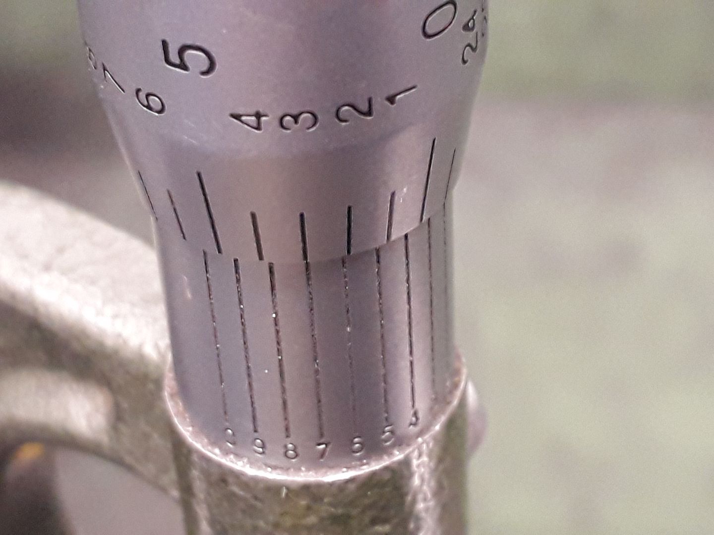
          Good enough to sneak up on 10mm dia with the 10ths micrometer


          Edited By JasonB on 07/08/2021 13:25:33

          Edited By JasonB on 07/08/2021 13:36:55

          #557418
          Ramon Wilson
          Participant
            @ramonwilson3

            Yes Jason point taken but then your lathe isn't a Myford wink


            Anything from the states is going to be prohibitively expensive – some of the postage costs on ebay are eye watering.

            I'll keep to my own inserts made from FC3 cutter shanks for the most part. Excellent HSS and 'free' too – come with every milling cutter laugh

            I'm not saying don't use them but I am saying a new comer doesn't need them – big difference

            Looks like you overshot that .007 BTWcheeky


            Edited By Ramon Wilson on 07/08/2021 14:56:00

            #557434
            JasonB
            Moderator
              @jasonb

              Though a Myford could do it too with the advantage of far more torque at the lower speeds due to belt drive and back gear. If it can do it with HSS then the GT inserts need no more force or rigidity

              I was really just trying to show the Doc that the GT inserts he has should be more than durable enough for roughing that arbor down to 1" say a three 40thou deep cuts and then a finish cut or two. You don't need any more power or rigidity for the 1 thou finish cuts that my machine may offer.

              They also work on my Unimat and I've seen them in use on Cowells lathes too so again a Myford should be up to using them.

              #557447
              Ramon Wilson
              Participant
                @ramonwilson3

                Not disagreeing with your input to Doc Jason just trying to show the otherside of the coin.

                I don't disagree with you either just after so many years in front of a lathe both at home and at work I just don't see the need for carbide per se at home on small lathes like a Myford or the modern mini lathe. I accept that technology has moved on in inserts but believe me I have stood in front of several Triumph 2000 lathes spitting out blue swarf hitting the back of the splash tray like bullets the resident cooling in the tray steaming as the heat hits it to know what it means to use them as they should be used but I don't want to do that on my lathe.

                As said, I use them for roughing EN24t which is tough on HSS when roughing but I don't use the leadscrew – just hand fed. I imagine your lathe has feedscrew for power feed. To my mind a Myford leadscrew and nut would soon suffer wear under frequent use for power feeding on that task alone.

                I know my Myford is capable of .250 cuts with a HSS tool of the right shape but it's pushing it to the limit – I don't care to stress the machine in that way if it's not neccessary.

                I took this pic a week or two back – still in fine fettle since c1979 wink

                dscn0096.jpg

                Regards – Ramon

                #557477
                Howard Lewis
                Participant
                  @howardlewis46836

                  Learning to grind a HSS toolbit is a useful skill to acquire. One day you may need a tool, of a form that is not available in carbide, so you HAVE to grind your own..

                  For the newbie HSS is more forgiving, a knock is less likely to chip it,

                  You can regrind HSS at 9:00 pm on a Saturday night when the suppliers of carbide tips have closed up for the weekend, and you have just chipped th last one, but want or urgently need to finish the job.

                  The angles don't have to be EXACT, If the "book" says 10 degrees and you grind 12 or 5, the world is not going to end. Tool life between needing to be reground may be shorter, but it will most probably do the job, for the time that it is needed..

                  In the same way, if you stone a radius onto the edge of the tool, and it is not 0.4 mm but 0.5 it will still do the job.

                  You may need to change speed or feed slightly, but we are model engineers, and not on piecework making parts for NASA, Elon Musk, or Richard Branson's spacecraft.

                  As a heretic, showing the other side of the coin, I have obtained superb finishes on inch bar by running a carbide tip at 100 rpm, liberally dosed with ordinary lubricating oil.

                  As someone told Douglas Bader, rules are for the obedience of fools and the guidance of wise men.

                  Knowing when and how to bend or break them is the important thing!

                  Howard

                  #557485
                  Dr_GMJN
                  Participant
                    @dr_gmjn

                    Appreciate the comments on tooling, although I’m pretty satisfied with the finish on EN1A with the GT tip now. Also on aluminium and brass, and on cast iron with the specific tips for that. I do have some mechanical sympathy, and wouldn’t pursue cutting if I thought something was amiss. I’m encouraged by the finish of the bores, which was with hand ground bits (and the bar itself). I’ll use HSS tooling for the connecting rods and rope wheel grooves anyway.

                    So back to the model, and more of the inevitable ups and downs…

                    Checked the mandrel for runout – needle didn’t move so that was ok;

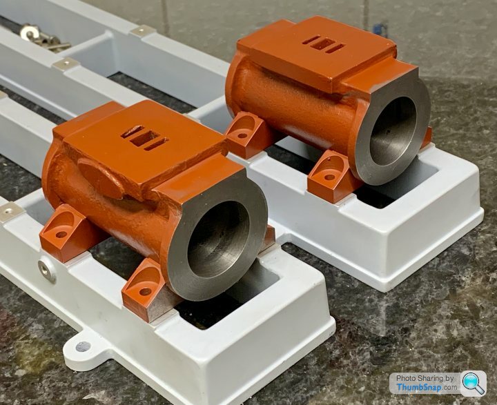
                    Marked out one casting, which was pretty much spot-on for symmetry:

                    Faced each end to the lines, checking with the callipers until it was right. In fact it ended up about 0.002” short, but whatever.

                    The other cylinder however was a problem. No matter how I checked it and marked it out, I couldn’t get the valve face symmetrical AND get the end flanges/flat areas each side of the valve face about equal. I skimmed the end faces to make sure any waviness on them wasn’t affecting things, but still the same. Didn’t seem to have any choice but to compromise on the symmetry, so now one flange is noticeably thinner than the other, and one flat shorter than the other (by about 0.5mm). Strange but the thin flange is only on one side of one end of the cylinder. This is the bad side:

                    This is the other side with pretty equal flanges:

                    With all the messing about I also managed to machine it short by 0.008”.

                    To be honest I’m pretty disappointed with it after trying to get everything spot-on. I’m half considering using the spare cylinder I’ve got, but that would mean somehow removing the feet from the other one. Seems like JB Weld might withstand the attention of a hammer (even after drilling out the screws of course). Could bore the cylinder away, but…I dunno.

                    What to you guys reckon? Stick with it or try again? There was definitely something slightly off with one cylinder in terms of valve block alignment and flange thicknesses, whereas I’d assumed both castings would be identical.

                    #557492
                    JasonB
                    Moderator
                      @jasonb
                      Posted by Dr_GMJN on 08/08/2021 00:21:53:

                      . Strange but the thin flange is only on one side of one end of the cylinder. This is the bad side:

                      Quite a common thing with castings where one half of the mould moves slightly relative to the other. Usually it can be "lost" with fettling and a bit of filling if really bad, I've had far worse than that. The Victoria I did earlier in the year has the same issue of one flange thicker than the other.

                      Possible to dremel the thick one down a bit and add a little JBW or body filler to the thin one if you feel the need.

                      As for the short cylinder you could bring the other one down to match if you wanted at least that way you don't have to keep thinking about any need to make other parts at different dimensions each side, though there is only one dimension I can think of that I may adjust depending where the short end is. I'd stick with it rather than start the extra cylinder and deal with any cosmetics at the end.

                      Have a read of this thread over on MEM to give you forewarning of what can be encountered with castings, post #17 deals with the mould halves moving. A bit more about preping castings to get them looking good here

                      #557499
                      Ramon Wilson
                      Participant
                        @ramonwilson3

                        You could increase the flanges thickness with epoxy putty enough to fool the eye but I agree with Jason – live with it. Castings are what they are full size or model. Symmetry is desired but not always achievable and your result is not excessively thin – certainly not worth setting up another cylinder, it may turn out the same, or even worse.

                        All looking good to me so far Doc, time to think about that next stage wink

                        Ramon

                        #557500
                        Dr_GMJN
                        Participant
                          @dr_gmjn

                          Ok guys that’s great, thanks.

                          Ramon, yes, after posting I was thinking that I could possibly use a bit of extra Milliput on the thin flange – I still need to go around the feet with filler to form the simulated cast radii there anyway.

                          Of course that still leaves the 0.5mm short flat on one cylinder top, but I might be able to correct that by filing the valve pad a bit.

                          The valve ports aren’t quite in the middle of their cast faces – one worse than the other. Presumably I can adjust the middle position of the valve slider to compensate, with no ill effects?

                          Couple more questions:

                          1) Talking of the valve face, there are a couple of small chunks missing from the sides of the inlet ports. Is it worth JB Welding them before facing them?

                          2) I’d like to use washers (or at least have the option) behind the cylinder cap bolts (7BA). Is there any reason I couldn’t reduce the PCD a fraction to allow this – I think they’d slightly overhang the edge as they are?

                          Onwards…

                          Cheers.

                          #557506
                          Ramon Wilson
                          Participant
                            @ramonwilson3

                            That's the only thing I've never liked about Stuart cylinder castings – those cast in valve ports. There are ways of correcting that and leaving as is and positioning the valve to suit is one. Filling with JB before machining could be done but if the machining then takes most of that way there is very little holding surface – possibly a potential of coming loose

                            Another is to machine the port surface lower then attach (bond) a plate which has the correct spacing and dimensions of the port milled in. Unless the cast ports are way out of position any slight discrepancy will not affect the working. A variation on that is to mill a pocket inside the confines of the port face and bond in an insert then mill the ports through to the existing ones in situ. Doing it this way keeps the casting visually intact from the outside.

                            If you really desire to use washers I'd reduce them in size rather than alter the PCD – easy enough to do a batch at a time on a small mandrel or possibly more in keeping, spotface the bolt holes?

                            Onwards it is yes


                            Edited By Ramon Wilson on 08/08/2021 09:34:47

                            #557510
                            Dr_GMJN
                            Participant
                              @dr_gmjn

                              I think I’ll leave the ports as they are, and see what they’re like after facing. They should improve with a skim anyway.

                              Yes I was concerned about the JB Weld coming loose, same with filling the break-throughs of the cylinder feet screws into the bores – tiny amount of surface to bond to. I might leave those un-filled as well. It says in the instructions that they will fill with oil and running-in debris, however, not sure how your silicone (or was it PTFE?) piston rings would generate any debris, or how they’d like being run over a pit? I’ll check to see if the rings actually pass over them.

                              Cheers.

                              #557512
                              JasonB
                              Moderator
                                @jasonb

                                I'd wait until you have faced the surface and then see what you have, often a corner of the casting will crispen up as the machining allowance is cut away. I found the ports were not equal on the one I made so tidied them up with a 2mm cutter, just going to about the same depth.

                                As for the "flat" areas either end of teh port face, wait until you come to fit the valve chest which is unlikely to be the same size rectangle as the mating one on the cylinder and you may need to machine some off anyway

                                I'd be going for studs and nuts on this one particularly as it is now representing a much larger engine, I seldom use washers.

                                #557517
                                Dr_GMJN
                                Participant
                                  @dr_gmjn

                                  OK thanks Jason.

                                  Yes, studs and nuts as per the 10V. I just think contrasting washers look nice, modeller’s license nothing more than that. I’ll see what the clearances are like and as suggested turn some down to suit or leave them off completely.

                                  #557537
                                  Ramon Wilson
                                  Participant
                                    @ramonwilson3

                                    Personally Doc I would still fill the holes in the bore with JBW. Left open, the packing, either PTFE or an O ring, could potentially be torn as it expands into the cavity as it passes.

                                    It is very unlikely to come out once cured infact the action of the piston would be to retain it – unlike any repair to the valve face where the surface area of contact would reduce as it is machined away

                                    BTW when I suggested spot facing the covers I did mean doing away with washers.

                                    Good luck with the next phase

                                    #557539
                                    JasonB
                                    Moderator
                                      @jasonb

                                      Should not really need to spot face as they are machined surfaces and most leave them unpainted, different on something like your sole plate on the 10V where nuts bear on a painted cast surface unless spot faced

                                      #557574
                                      Dr_GMJN
                                      Participant
                                        @dr_gmjn

                                        So the cylinders are now the same length to 1/2 thou, and the faces seem to be equally spaced from the foot holes too (when placed back-to-back on the surface plate, a drill can be pushed through the pairs of holes).

                                        I think I can correct the thin flange with Milliput, and I think the slightly long top flat can be corrected too – but after looking again it’s not really noticeable anyway, and will be partially hidden under the valve gear.

                                        Still kicking myself for the length error, which is 7 1/2 thou under. I don’t think it will matter – it’s about the thickness of gasket paper, but that’s not what annoys me about it. It’s a lesson that should have been learned already.

                                        The foot screw break-throughs are filled with JB Weld which is currently setting:

                                        I also filled a few odd cracks around the foot parts. Tomorrow I’ll radius Milliput around them and begin correcting the flange.

                                        I quickly machined a cylinder cap disc, just to see how out of alignment the flange O/Ds are. They are pretty good, with only one side of one casting requiring a bit of reducing with a file:

                                        The disc is also pretty much perfectly tangential to the top flats, which I found odd, because others I’ve seen stuck up above, which I don’t like the look of. It was suggested JB Wrld could be added to the flat to compensate.

                                        Confused, I checked the drawing and found my “best fit” disc was smaller than defined on the drawing (see image for the figures):

                                        The diameter in the drawing has + 1/32” next to it which I assume is some kind of upper tolerance limit?

                                        I can only think that deliberately making the caps oversized is to allow for cladding (which I’m not using)?

                                        It also means I may have to reduce the stud PCD anyway – washers or not) to give the nuts enough room.

                                        #557582
                                        Dr_GMJN
                                        Participant
                                          @dr_gmjn

                                          Question about the front (piston rod) cover:

                                          On the 10V it was specified as a reamed hole to suit the piston rod, meaning the entire cylinder/piston/cover/gland nut/cross head etc all had to be machined to fine tolerances to avoid binding. Basically three elements had to be perfectly aligned for it to work properly. I did wonder why the cylinder cover and gland nut were so critical, beacause as far as I could see, the packing would conform to whatever alignment the piston and cross head gave, and would seal because it was compliant.

                                          This P.R. model is the opposite; it states in the instructions that a clearance hole in the cover is preferable, for the reasons I’d assumed above. Also says the locating spigot should be a loose fit. So there’s deliberate built-in radial play.

                                          Following on from that – if the cylinder facing at the front end isn’t perfectly normal to the axis, does it even matter in practical terms? Surely any skew in the cover alignment will just be taken up by the packing? I realise the mandrel machining and cutting the front face first is good practice, but…dare I ask if it’s that important given the above?

                                          #557599
                                          JasonB
                                          Moderator
                                            @jasonb

                                            I tend to go for quite close fitting pistons and also make the cover spigots a close fit in the cylinder, close enough that when the cylinder is used to gauge the spigots diameter the two will hold together. I also ream the piston rod holes while the cover is still in the chuck to ensure the hole is concentric to the spigot.

                                            As for the glands I ream those but for ones like the Victoria make the spigot a few thou smaller than the cavity or if threaded glands then tighten down the die so there is a bit of sideways play as the gland recess in the cover needs to be done once the cover is reversed in the chuck. I do tend to use soft jaws for the covers, not only to help keep the features concentric but mostly to have something to push the cover back against so there is no wobble plus you can easily holed the thin edges.

                                            Cover in place, no gland or rings.

                                            #557610
                                            Ramon Wilson
                                            Participant
                                              @ramonwilson3

                                              At risk of repeating myself one area to ensure smooth running at low pressure/slow speed is reducing friction to an absolute minimum. One area where tolerances can quickly build up to create such is the relationship between piston and cylinder piston rod and gland. Two other areas pose similar challenges – the cross head and bars and the main bearing/crankshaft alignment.

                                              I too use soft jaws but hold on the spigot that sits inside the cylinder. That is previously turned to a tight but not push fit in the respective cylinder. Previously the gland has been machined but not drilled through to finish size. The outer of the cover is then turned to take the gland (another tight fit) and the gland is bolted in place. The two are drilled, bored and reamed to ensure maximum concenticity. The boring is just a scrape to true the drilled hole. The two are marked inobtrusively to ensure the correct pairing. If soft jaws are not available then a simple fixture drilled and tapped two or three holes on the cover PCD can have a recess finish bored until the cover just snaps in place and held with bolts – as accurate as the fit of the spigot and the lathe. The reamed hole in the cover could be eased slightly if after fitting the gland packing there is any sign of binding.

                                              If – an O ring is used for packing, then the concentricity of piston to rod (and subsequently to liner) needs to be very acurate. Achievable by turning the finish OD of the piston on the rod itself but that will only be as good as the concentricity of the rod held in the lathe.

                                              By using PTFE packing however the tolerance of the piston can be relaxed considerably eliminating any minor eccentricity causing tight spots – the packing taking any minor deviation up without loss of seal or compression. This gives an extremely friction free set up with no loss of pressure. All the steam engines I have made so far have had this arrangement and will run extremely slowly if required. ( I/C engines of course are a different matter requiring a completely opposite approach)

                                              The axis of the rod also needs to run as straight as achievable in both planes. This can be taken care of by very slight movement of the cylinder in the horizontal plane and by delicate scraping of surfaces /using very thin shims in the vertical. The rod should not deviate in height or sideways movement through out it's stroke.

                                              As you work through the engine you should pay attention to whatever you are machining is leading to accuracy for the next step – ends done of a true mandrel should be square to the bore. piston rod bores done off the back face of the cover and the spigot likewise. Not always the quickest I agree but eliminating potential inaccuracies as you proceed.

                                              We all do things differently but as always it's down to choice – Jason has his preferred methods as do I. In some quarters perhaps others may see niether of us as correct.

                                              As implied, I'm sure I have said this before but I hope it's not seen as labouring the point. Like Jason it's based on successful outcomes over several builds along with full size working practices over the years -make the most of both and any others input that makes sense.

                                              Keep at it – it's all looking good so far

                                              Ramon

                                              #557776
                                              Dr_GMJN
                                              Participant
                                                @dr_gmjn

                                                Thanks guys – plenty to digest. I'm just fettling the castings to increase the flange thickness and put the remaining simulated radii in place around the feet.

                                                Question about the mill mandrel for cutting the feet and valve face:

                                                How do you align and check the mandrel horizontally and in the y-direction on the mill bed?

                                                I could imagine it's difficult with a dial gauge because the part is cylindrical, and any run-off along the top (due to x-misalignment) could be misinterpreted as a droop even though the bar is horizontal

                                                Likewise, drop off in the reading along the side could be interpreted as a skew, if the bar isn't horizontal.

                                                So it would seem a bit chicken and egg?

                                                Probably missing something very easy, but…how to you do it?

                                                Cheers.

                                                #557804
                                                Ramon Wilson
                                                Participant
                                                  @ramonwilson3

                                                  Depends on how you are going to hold the mandrel.

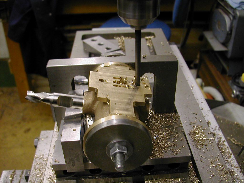
                                                  If using a dividing head you would need to clock it in both planes but for the most part I use an angle plate. Set the angle plate square to the table and clock then bolt the mandrel to the angle plate. If the angleplate is as square as it should be then the mandrel will be in the right planes. I always face the rear of the mandrel with a slight recess so when it is bolted up it pulls up tight on the outer land. You can still run a clock along it but you should be able to trust this set up if the kit is good.

                                                  I've just had a look but can't find an image though I'm sure I have one. I'll try a better search

                                                  Ramon

                                                  #557806
                                                  Ramon Wilson
                                                  Participant
                                                    @ramonwilson3

                                                    Here you are Doc

                                                    This shows the Mc'Onie cylinder being machined after doing the bore as you have

                                                    cyl 010.jpg

                                                    Hope that helps some – Ramon

                                                    #557822
                                                    Dr_GMJN
                                                    Participant
                                                      @dr_gmjn

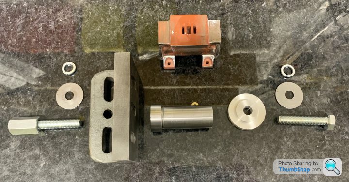
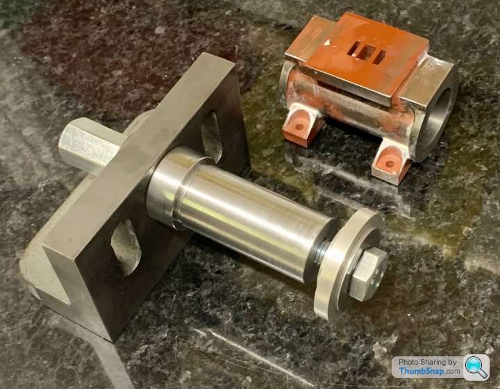
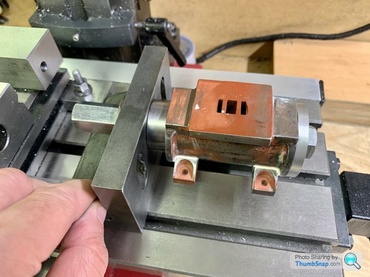
                                                      Thanks Ramon, yes that’s very helpful. This is what I’ve made so far this evening. I did think about rebating the boss, but then figured I was boring it to 10mm anyway, so the face might have got a bit thin:

                                                      I’ve never used that angle plate before. I checked with a square and it seems OK, so I can set up as you suggest, and hopefully it will work out level.

                                                      Intention is to bolt the feet to the steel strips I used for boring, and somehow clamp them to the bed. Perhaps I could use the vertical slots in the angle plate for securing the mandrel, and the feet will then rest in the bed, or some packing.

                                                      I thing I’ll try the shell mill for facing the valve face.

                                                    Viewing 25 posts - 351 through 375 (of 1,206 total)
                                                    • Please log in to reply to this topic. Registering is free and easy using the links on the menu at the top of this page.

                                                    Advert

                                                    Latest Replies

                                                    Viewing 25 topics - 1 through 25 (of 25 total)
                                                    Viewing 25 topics - 1 through 25 (of 25 total)

                                                    View full reply list.

                                                    Advert

                                                    Newsletter Sign-up